Ilmvac LVS 110 Tp ecoflex User manual
Operation Manual
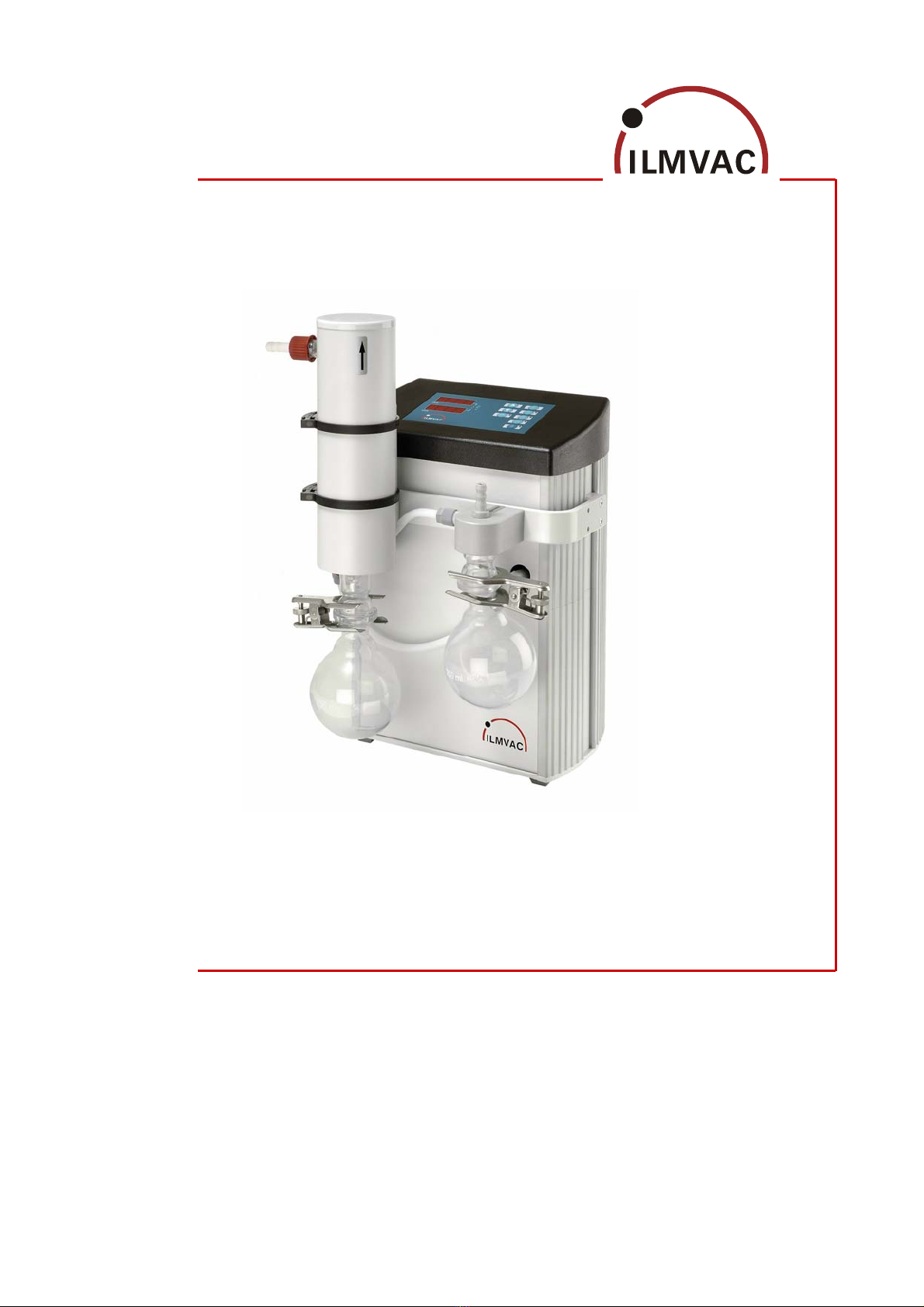
Laboratory - Vacuum - System
Type LVS 110 Tp ecoflex
113184
2008-05-21

We are constantly working on the further development of all our product types.
Reprinting or reproduction of this manual, including extracts, is not allowed without the prior written permission of
ILMVAC GmbH.
All rights under the copyright laws are expressly reserved by ILMVAC GmbH.
We reserve the right to make changes and amendments.
ILMVAC GmbH
Am Vogelherd 20
98693 Ilmenau, Germany
Telephone: +49 36 77 60 40
Fax: +49 36 77 60 41 10
E-mail: [email protected]
Internet: http://www.ilmvac.de
http://www.ilmvac.com

Contents
Contents
1Important Information.............................................................................................................5
1.1 General Information ..................................................................................................................5
1.2 Target Groups...........................................................................................................................5
1.3 Intended Use.............................................................................................................................5
1.4 Use for an Unauthorized Purpose ............................................................................................5
1.5 Safety Devices ..........................................................................................................................6
1.6 Meaning of the Warning notes ..................................................................................................6
1.7 Product Standards, Safety Regulations....................................................................................6
2Basic Safety Instructions .......................................................................................................7
2.1 General Information ..................................................................................................................7
2.2 Electricity...................................................................................................................................7
2.3 Mechanical Systems .................................................................................................................8
2.4 High Temperatures ...................................................................................................................8
2.5 Hazardous Substances.............................................................................................................9
3Description ............................................................................................................................10
3.1 Design and Function ...............................................................................................................10
3.1.1 Laboratory-Vacuum-System ...................................................................................................10
3.1.2 Diaphragm pump ....................................................................................................................11
3.1.3 Vacuum Controller ..................................................................................................................11
3.1.4 Additional Operating pad ........................................................................................................12
3.2 Areas of Application ................................................................................................................12
3.3 Scope of Delivery....................................................................................................................12
3.4 Example of application............................................................................................................12
3.5 Accessories.............................................................................................................................13
4Technical Data.......................................................................................................................14
4.1 View of device and dimensions...............................................................................................14
4.2 Intake Pressure / Pumping Speed – Diagram ........................................................................14
4.3 Device data .............................................................................................................................15
5Assembly and Installation....................................................................................................16
5.1 Unpacking ...............................................................................................................................16
5.2 Installation and Connection.....................................................................................................16
5.2.1 General instructions ................................................................................................................16
5.3 Storage....................................................................................................................................17
5.4 Scrap Disposal ........................................................................................................................17
6Operation ...............................................................................................................................18
6.1 Control panel...........................................................................................................................18
6.1.1 Starting up...............................................................................................................................18
6.2 Operating modes of the Controller..........................................................................................19
6.2.1 Selection, display of operating modes ....................................................................................20
6.2.2 Setting / changing the control parameters at the controller ....................................................20
6.2.3 Setting the selected control parameters .................................................................................21
6.2.4 Querying the set values ..........................................................................................................21
6.2.5 Changing the pressure during operation ................................................................................21
6.2.6 Set minimum pressure ............................................................................................................21
6.2.7 Venting the system .................................................................................................................21
6.2.8 Setting the after-running time for the cooling water................................................................22
6.3 Calibration...............................................................................................................................22
6.3.1 Run via control panel ..............................................................................................................22
113184 3

Contents
6.4 Operation using the "ILMVAC-Control" .................................................................................. 23
6.4.1 Menu item: „File“ .................................................................................................................... 25
6.4.2 Menu item: „Settings!“ ............................................................................................................ 26
6.4.3 Menu item: „Alarm“................................................................................................................. 28
6.4.4 Menu item: „Calibrate“............................................................................................................ 29
6.4.5 Menu item: „Factory settings“................................................................................................. 30
6.4.6 Operation via RS 485 (according to NAMUR NE 28) ............................................................ 31
6.5 Table of solvents .................................................................................................................... 32
7Maintenance and Servicing................................................................................................. 33
7.1 General Requirements ........................................................................................................... 33
7.2 Maintenance Performed by the User ..................................................................................... 33
7.2.1 Maintenance of the diaphragm pump..................................................................................... 33
7.2.1.1 Disassembly ........................................................................................................................... 34
7.2.1.2 Assembly................................................................................................................................ 35
7.2.1.3 Test......................................................................................................................................... 36
7.2.2 Maintenance of the vacuum controller ................................................................................... 36
7.2.3 Maintenance of other components......................................................................................... 36
7.3 Maintenance by the Manufacturer.......................................................................................... 36
7.4 Damage Report ...................................................................................................................... 36
8Troubleshooting ................................................................................................................... 37
9Spare Parts Overview .......................................................................................................... 38
9.1 Maintenance kit - Diaphragm Pump....................................................................................... 38
9.2 Exploded view - LVS 110 Tp ecoflex ..................................................................................... 39
9.2.1 Spare parts list - LVS 110 Tp ecoflex.................................................................................... 40
4 113184

Important Information
1 Important Information
1.1 General Information
The ILMVAC Laboratory-Vacuum-System LVS 110 Tp ecoflex conform to the
• 2006/95/EC Low Voltage Directive
• 2006/42/EC Machinery Directive
• 2004/108/EC Electromagnetic Compatibility Directive
The CE sign is located on the rating plate. Observe the binding national and local regulations
when fitting the pump into installations.
Our products are sold worldwide and can therefore be equipped with the typical national
plugs and for the various voltages. You will find more information about the available designs
under http://www.ilmvac.de.
1.2 Target Groups
This Operating Manual is intended for the personnel planning, operating and maintaining
ILMVAC Laboratory-Vacuum-Systems.
This group of people includes:
• Designers and fitters of vacuum apparatus,
• Employees working on commercial laboratory and industrial vacuum technology applications and
• Service personnel for laboratory-vacuum-system LVS 110 Tp ecoflex.
The personnel operating and maintaining the laboratory vacuum systems must have the
technical competence required to perform the work that has to be done.
The user must authorize the operating personnel to do the work that has to be done.
The personnel must have read and understood the complete Operating Manual before using
the laboratory-vacuum-systems.
The Operating Manual must be kept at the place of use and be available to the personnel
when required.
1.3 Intended Use
• The laboratory-vacuum-system may only be operated under the conditions stated
– in the "Technical Data" section,
– on the type plate, and
– in the technical specification for the order concerned.
• Laboratory-vacuum-systems are approved for extracting, pumping and compressing gases and va-
pours. If these gases and vapours are toxic or explosive, then the user must observe the currently
valid safety regulations for this application. Special types of diaphragm pumps are available for ag-
gressive and explosive gases.
• Laboratory-vacuum-systems are intended for generating vacuums with ultimate pressures of
around 2 mbar.
• The in-built diaphragm pump has been designed to have high resistance to aggressive gases.
• The active heating of the pump heads eliminates the need for a gas ballast valve.
1.4 Use for an Unauthorized Purpose
It is forbidden to use the pump for applications deviating from the technical data stated on
the type plate or the conditions stated in the supply contract, or to operate it with missing or
defective protective devices.
113184 5
Important Information
1.5 Safety Devices
– Measures such as the following are for the safety of the operating personnel:
• electrical connection with a protective conductor (operating mode S1) and an earthing plug,
• fine-wire fuse (slow-blow),
• “Hot Surface" label on the pump body (warning notice),
• completely enclosed casing,
• identification WEEE,
• glass components with a transparent plastic coating which protects them against bursting and
cracking, cooler isolated.
The laboratory-vacuum-system must not be operated without these elements.
1.6 Meaning of the Warning notes
Take note of the warning notices. They are in the following box:
CAUTION ! / WARNING !
Hazard which may lead to serious injuries or material damage.
1.7 Product Standards, Safety Regulations
ILMVAC LVS 110 Tp ecoflex meet the following product standards:
DIN EN 292-1, DIN EN 292-2 Safety of machines, basic terminology
DIN EN 1012-2 Compressors and vacuum pumps
DIN EN 60204-1 Electrical equipment of machines
EN 50110-1 (DIN VDE 0105-100) Operation of electrical installations
EN 61010-1 Safety for laboratory devices
EN 50081-1-2 Electromagnetic compatibility (EMC)
Generic specification - Interference resistance
for residential, business and industrial areas, and small businesses
EN 50082-1-2 Electromagnetic compatibility (EMC)
Generic specification - Interference emission
for residential, business and industrial areas, and small businesses
EN 55014 Radio disturbance characteristics of electrical equipment and
systems
EN 61000-3-2/3 Electromagnetic compatibility (EMC)
Directive 2006/42/EC Law and Administration Regulations relating to Machinery
Directive 2002/95/EC RoHS Restriction of use of certain hazardous substances
The following additional safety regulations apply in the FR Germany:
BGV A2 Electrical equipment and operating materials
VBG 5 Power-driven machines
BGR 120 Guidelines for laboratories
BGI 798 BG hazard assessment in the laboratory
Observe the standards and regulations applying in your country when you use the LVS.
6 113184

Basic Safety Instructions
2 Basic Safety Instructions
2.1 General Information
CAUTION !
Warning notices must be observed. Disregarding them may lead to damage to health
and property.
The laboratory vacuum systems must be operated by personnel who can detect impending
dangers and take action to prevent them from materialising.
The user/operator is responsible for correct installation and safe operation.
Prevent condensate collecting in the pump. When pumping vapours which tend to condense,
please ensure that the pump is at operating temperature and that the gas ballast valve is o-
pen when the pump is switched on.
If there is more than one load on one LVS, they must be separated by check valves.
The manufacturer or authorized authorised workshops will only service or maintain the labo-
ratory vacuum system if it is accompanied by a fully completed damage report. Precise in-
formation about the contamination (also negative information if necessary) and thorough
cleaning of the laboratory vacuum system are legally binding parts of the contract.
Contaminated laboratory vacuum systems and their individual parts must be disposed of in
accordance with the legal regulations.
The local regulations apply in foreign countries.
2.2 Electricity
The LVS 110 Tp ecoflex are supplied for operating mode S1. Please note that the testing
must be repeated in accordance with DIN EN 0105, DIN EN 0702 and BGV A2 in case of
portable devices.
The local regulations apply in foreign countries.
Please note the following when connecting to the electrical power supply system:
• The electrical power supply system must have a protective connector according to DIN VDE 0100-
410 (IEC 60364-4-41).
• The protective connector must not have any breaks.
• The connecting cable must not be damaged.
• All interfaces are under low voltage according to DIN VDE 0100-410.
113184 7

Basic Safety Instructions
2.3 Mechanical Systems
Improper use can lead to injuries or material damage. Observe the following instructions:
• Only operate the LVS with hoses of the specified dimensions.
• The maximum permissible pressure of 1 bar at the suction connection must not be exceeded.
• Solid particles in the pumping medium impair the pumping action and can lead to damage. Prevent
solid particles penetrating into the pump.
• Hazardous substances must be separated out as far as this is technically possible before they
reach the pump.
• External mechanical stresses and vibrations must not be transmitted to the pump. Only use flexible
laboratory hoses for connecting laboratory vacuum systems.
• The overpressure generated at the pressure port must not exceed 1 bar.
• The pump must not be used to suck up fluids. Lay the exhaust pipe so that it slopes downwards, so
allowing condensate to flow out of the pump. Collect the condensate and dispose of it in an envi-
ronmentally compatible manner.
When handling glass vessels, pay attention to:
• Only use glass vessels with a plastic coating for splinter protection.
• Only use vessels which are suitable for use with vacuums (e.g. round-bottomed flasks).
We recommend that only glass components supplied by the manufacturer are used.
Do not use Erlenmeyer flasks.
• Before each evacuation, check glass vessels for damage which might impair their strength, replace
them if any such damage is found.
• Do not heat glass vessels on one side only.
• Retardation of the boiling of the gases to be pumped can lead to a sudden pressure increase. Pre-
vent retardation of boiling by means of suitable measures (e.g. turbulent agitation).
2.4 High Temperatures
Prevent the following maximum permissible temperatures from being exceeded.
• + 40 °C for the environment, and
• + 60 °C for the gas to be pumped.
The motor for single phase alternating current is protected against overload by an integrated
motor protection switch.
8 113184

Basic Safety Instructions
2.5 Hazardous Substances
WARNING !
The operating company bears the responsibility for the use of the laboratory
vacuum system.
Hazardous and harmful substances must be effectively prevented from escaping!
Ensure that all lines and connections are leak tight.
Handle exhaust gases in accordance with the requirements of the emission protection regu-
lations.
Do not operate the laboratory vacuum system without a separator. The separator can only
be emptied after the apparatus has been vented.
Dispose the condensate in an environmentally compatible manner!
The emission condenser has a safety valve. The air evacuation duct with hose must be kept
clear and lead into a suitable air evacuation duct. Throttling the air evacuation duct can da-
mage the valves of the diaphragm pump.
Hazardous substances in the gases to be pumped can cause personal injuries and property
damage. Pay attention to the warning notices for handling hazardous substances.
The local regulations apply in foreign countries.
Combustible Gases
The user must assess the process in accordance with Directive 1999/92/EC (ATEX 137) for
the extraction of explosive gas/air mixtures inside or outside a similar environment. In accor-
dance with the requirements indicated by this assessment, a suitable device must be se-
lected which fulfils the specifications of Directive 94/9/EC (ATEX 95).
Aggressive gases
The diaphragm pump used is highly resistant to chemicals. In the case of particularly ag-
gressive gases or products, the materials used for the pump parts in contact with gas must
be assessed (as described in chapter 3.1.2).
Poisonous gases
Use a separator when pumping poisonous or harmful gases. Prevent such substances from
leaking out of the appliance or pump. Treat these substances according to the applicable
environmental protection regulations.
The diaphragm pump, control valves and hose lines can be damaged by poisonous or ag-
gressive gases.
Test the strength and leak-tightness of the connecting lines and the connected apparatus.
Prevent environmental poisons, e.g. mercury, getting into the diaphragm pumps.
Fulfil the requirements, for example:
• German Hazardous Substances Regulation (GefStoffV) of 23. December 2004
• Regulations 2006/121/EC (classification, packaging and identification of hazardous substances),
• Manufacturer's safety data sheets on hazardous substances.
113184 9
Description
3 Description
3.1 Design and Function
3.1.1 Laboratory-Vacuum-System
A rotary evaporator can achieve its full performance capability as a result of precisely controlled, ana-
lytically pure vacuum.
The Laboratory Vacuum System “LVS 110 Tp ecoflex” has been specifically designed to meet these
requirements.
The chemically resistant diaphragm pump “MPC 104 Tp” provides an oil-free, dry and thus analytically
pure vacuum to an ultimate pressure of < 2 mbar. The maximum pumping speed of 1.1 m3/h is
matched directly to the actual requirement by the speed control of the powerful and extremely quiet
24 V EC drive of the diaphragm pump.
The LVS thus always works optimally. With a high quantity of gas under full power = maximum speed,
with a low quantity of gas correspondingly slower. That protects the diaphragm pump, reduces the al-
ready low energy consumption, and considerably reduces the noise level. At the same time, this de-
sired reduction of the stroke rate leads to a reduction of the pump temperature and to increased con-
densation. To prevent this, the pump heads are held at a constant temperature by a control system.
Investigations have shown that this eliminates the need for a gas ballast valve. A gas ballast valve (see
chapter 3.5) can be optionally mounted if this is not possible under certain conditions.
The new design, the functional and well-arranged structure, and the smaller dimensions allow trouble-
free, time-saving cleaning.
A second operating console (operating pad) can easily be connected for remote control of the LVS 110
Tp ecoflex, for example for working in the extraction hood or in other critical areas.
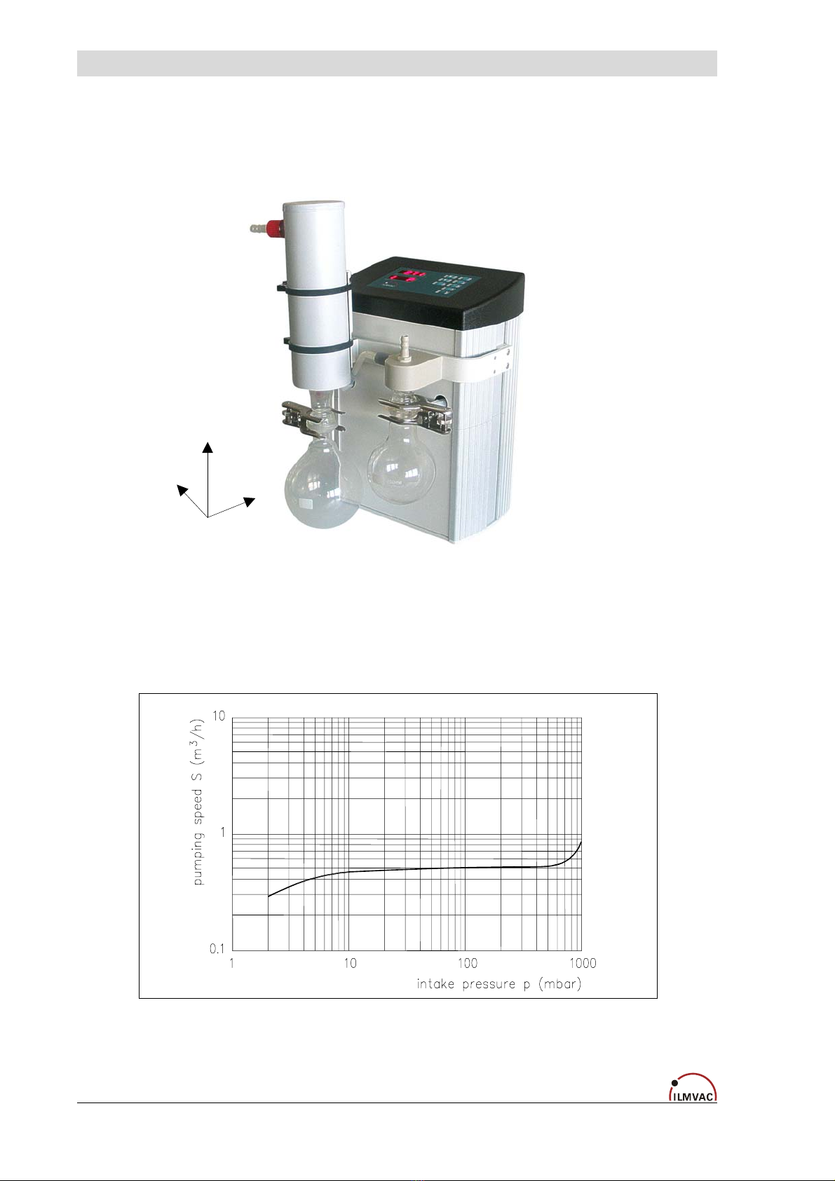
The LVS 110 Tp ecoflex is supplied complete with a suction-side separator and a pressure-side emis-
sion condenser in the form of an intensive cooler.
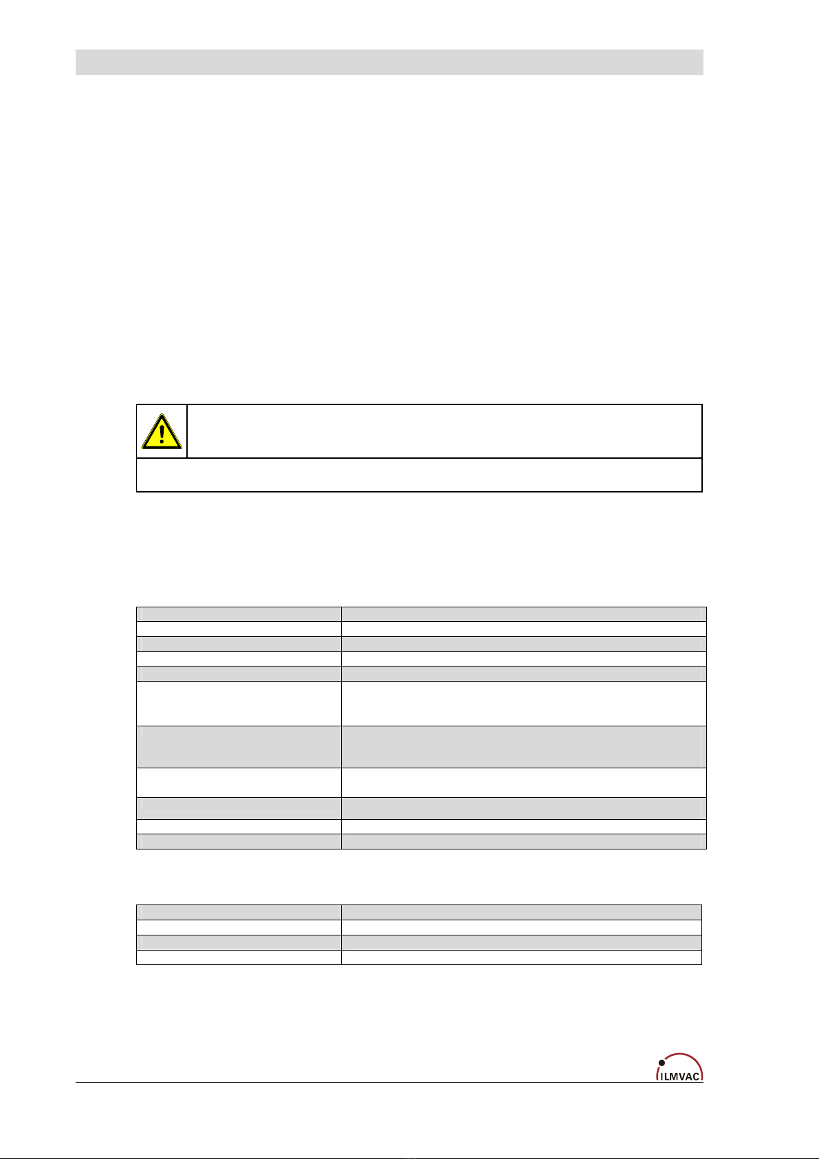
1 Suction side connection
hose nozzle for hose DN8
2 Separator
(round-bottomed flask) suction side
3 Casing
Diaphragm pump MPC (fitted in the casing)
with main switch
4 Control level Vacuum Controller
with integrated grip recess
5 Emission condenser KD 500/5 insulated
at the pressure side with safety valve
and cooling water connections,
outgoing air connection (hose nozzle for hose DN8)
Fig. 1a LVS 110 Tp ecoflex - Front view
6 Separator (round-bottomed flask) outgoing air side
7 Cooling water (feed flow / back flow)
8 Connection outgoing air
hose nozzle for hose DN8
9 Main switch (Power)
10 Main device fuse
11 Plug for non-heating device power cable (Main in)
12 PC connector (RS 232)
13 Connector socket for operating pad (optional)
14 Connector socket for water valve (optional)
15 Inert gas connection DN 4
Fig. 1b LVS 110 Tp ecoflex - Rear view
10 113184
Description
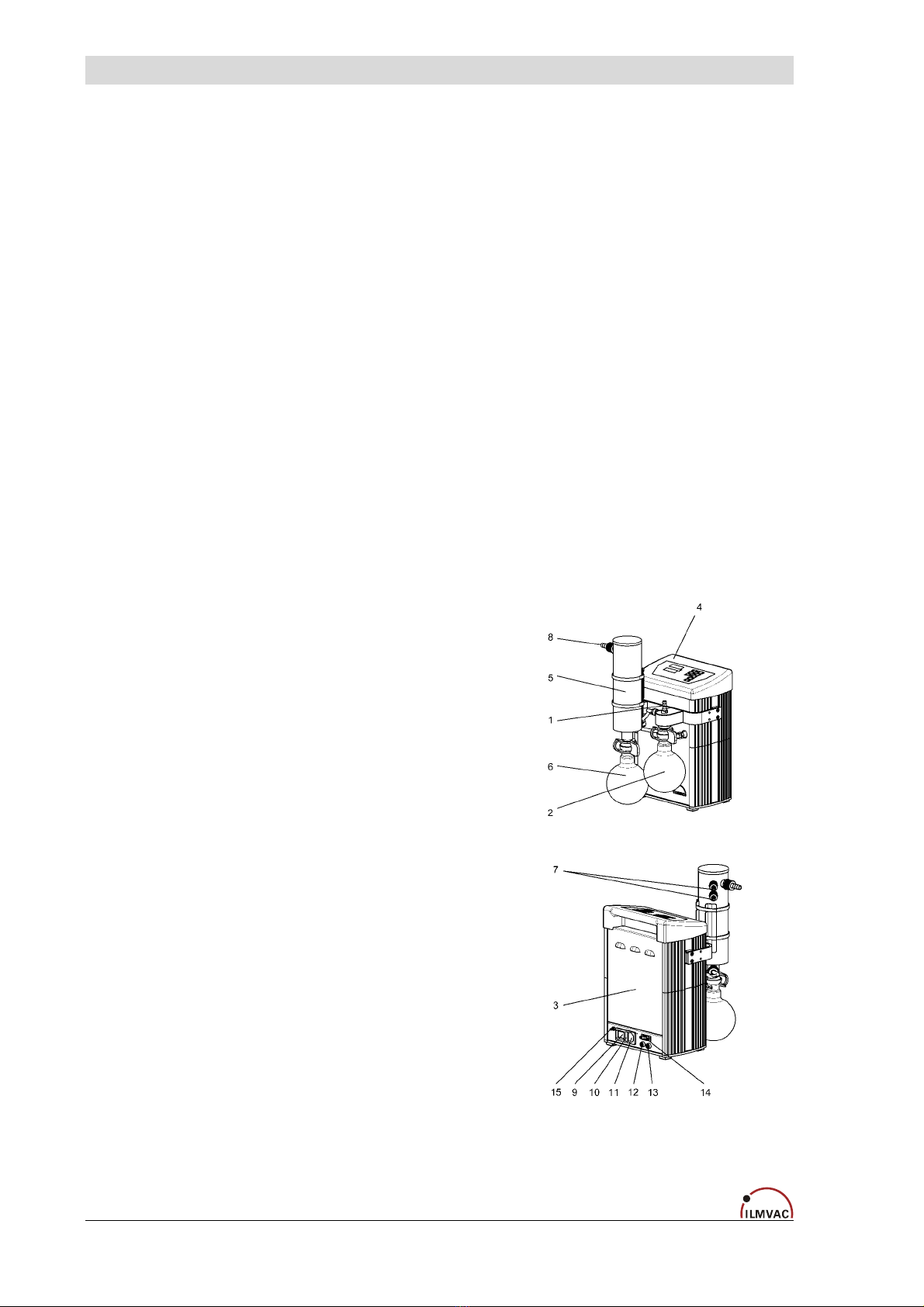
3.1.2 Diaphragm pump
Design:
The diaphragm pump MPC 104 Tp con-
sists of a pump body and a drive motor.
The pump body consists of a drive
shaft and four pump heads.
Each pump head contains the
diaphragm and the work valves.
The two pump heads are arranged
opposite each other.
In a three-stage (T) diaphragm pump,
the two pump heads are connected
in parallel, two further pumps in
series.
The pump heads are driven via an
eccentric shaft with a connecting
rod.
Fig. 2 Diaphragm pump MPC 104 Tp
Function:
Motor, eccentric shaft and connecting rod set the diaphragms in stroke movement. This
changes the size of the space between the diaphragms and pump head (pump chamber).
Increasing the size of the pump chamber opens the inlet valve while the outlet valve is clo-
sed (intake process). Decreasing the size of the pump chamber ejects the gas through the
outlet valve.
The valves are actuated by the gas being pumped. A large proportion of fluid in the dia-
phragm pump minimizes the pumping efficiency.
Component Materials
Connection- / pump head PTFE with carbon-fibre reinforcing
Seal EPDM
Screw fitting PVDF / PP
Valves PEEK
Diaphragm fabric reinforced with a PTFE layer
Connecting elements PP
Hose PTFE
PTFE with carbon-fibre reinforcement, electrically conductive (with manufacturer's certificate
of electrical conductivity).
Material resistance to aggressive media see: “Kunststoff Kautschuk Produkte“, Jahreshand-
buch der Verarbeiter 2000/2001 ("Plastic, Rubber Products“, Annual Handbook of the Proc-
essor 2000/2001), Publisher Hoppenstedt Darmstadt, Vienna, Zurich.
3.1.3 Vacuum Controller
Into the existing hardware of the vacuum controller VCZ 424 a particularly developed soft-
ware was installed.
Technical data: see chapter 4
Operation: see chapter 6
113184 11
Description
3.1.4 Additional Operating pad
The controlled LVS can be ordered with a separate operating pad in order to be able to op-
erate it from an external keypad. It is also possible to connect the operating pad to an exist-
ing device at a later date. In order to do this, the optionally supplied operating pad has to be
purchased under order no. 113513.
It is then activated by a one-off registration via the PC program "ILMVAC-Control" (display
address: mount 1 on 2) see chapter 6.4.5).
3.2 Areas of Application
The LVS 110 Tp ecoflex is intended for:
• vacuum filtration, vacuum distillation and vacuum drying.
• use in physical and chemical laboratories in trade and industry.
• pumping and compressing neutral and aggressive gases and vapours.
• generating a vacuum up to an ultimate pressure of around 2 mbar without using the lubricant oil.
Special designs:
• Special LVS can be supplied after consultation with the manufacturer or for a corresponding supply
contract.
• Motors for different voltages.
3.3 Scope of Delivery
The scope of delivery is specified in the supply contract.
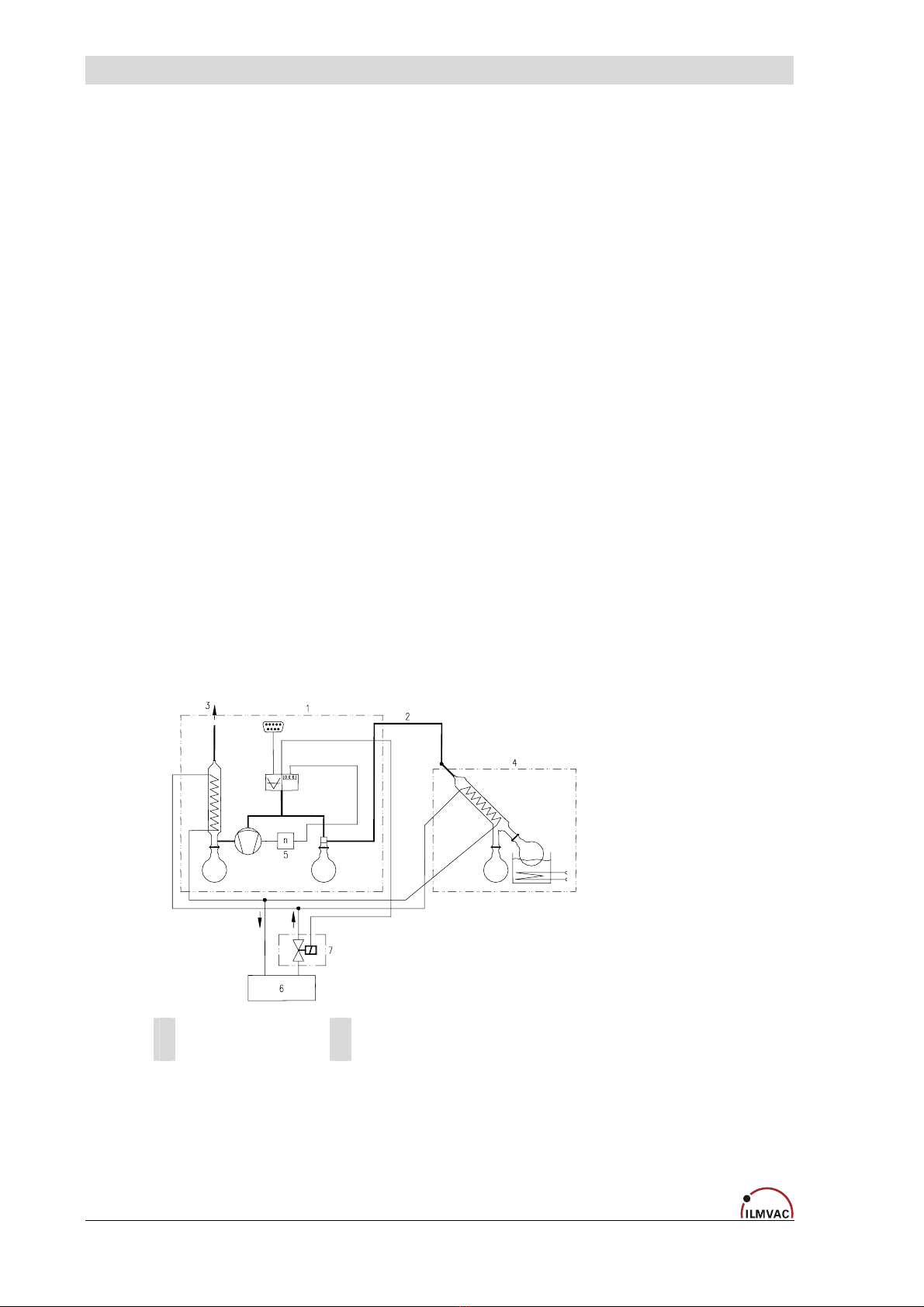
3.4 Example of application
1 LVS 110 Tp ecoflex 4 Rotary vaporizer *
2 Suction line * 5 Coolant system, un pressurised run back *
3 Outgoing air 6 Water valve WV *
Fig. 3 Example of application – LVS 110 Tp ecoflex
* Not included in the scope of delivery
12 113184
Description
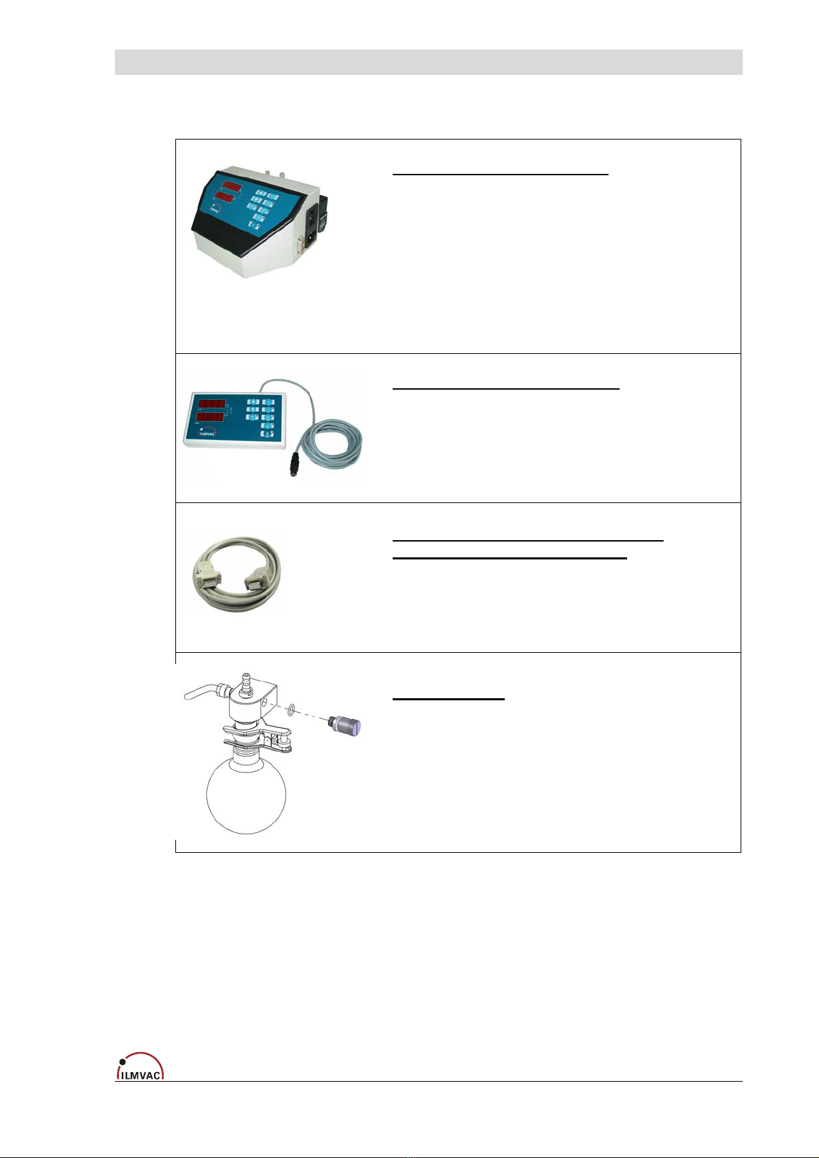
3.5 Accessories
Vacuum Control-Box VCB 424 cv
Table model as digital, chemical-resistant vacuum regulator.
With integrated sensor, airing -, control- and check valve.
Connection vacuum apparatus: DN 8
Connection vacuum pump: DN 8
Connection inert gas: DN 4
Connection water valve: Binder plug 4-pole 24V DC
Order no. 600037
Operating pad complete – VCZ 424
For external operation with a controlled laboratory vacuum system.
(maximum distance from basic device, approx. 3 m)
Order no. 113513
+ CD
"ILMVAC-Control" operating software
with the dual data cable VCZ 424
to connect the vacuum controller to the PC
Order no. 620617
Gas ballast valve (as from series 08/2007)
Order no. 400599-01
113184 13
Technical Data
4 Technical Data
4.1 View of device and dimensions
(W)
(H)
(D)
Fig. 4 View of device and dimensions (see chapter 4.3)
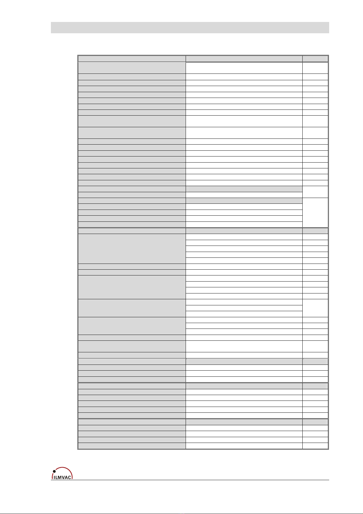
4.2 Intake Pressure / Pumping Speed – Diagram
Fig. 5 Intake Pressure / Pumping Speed – Diagram
14 113184
Technical Data
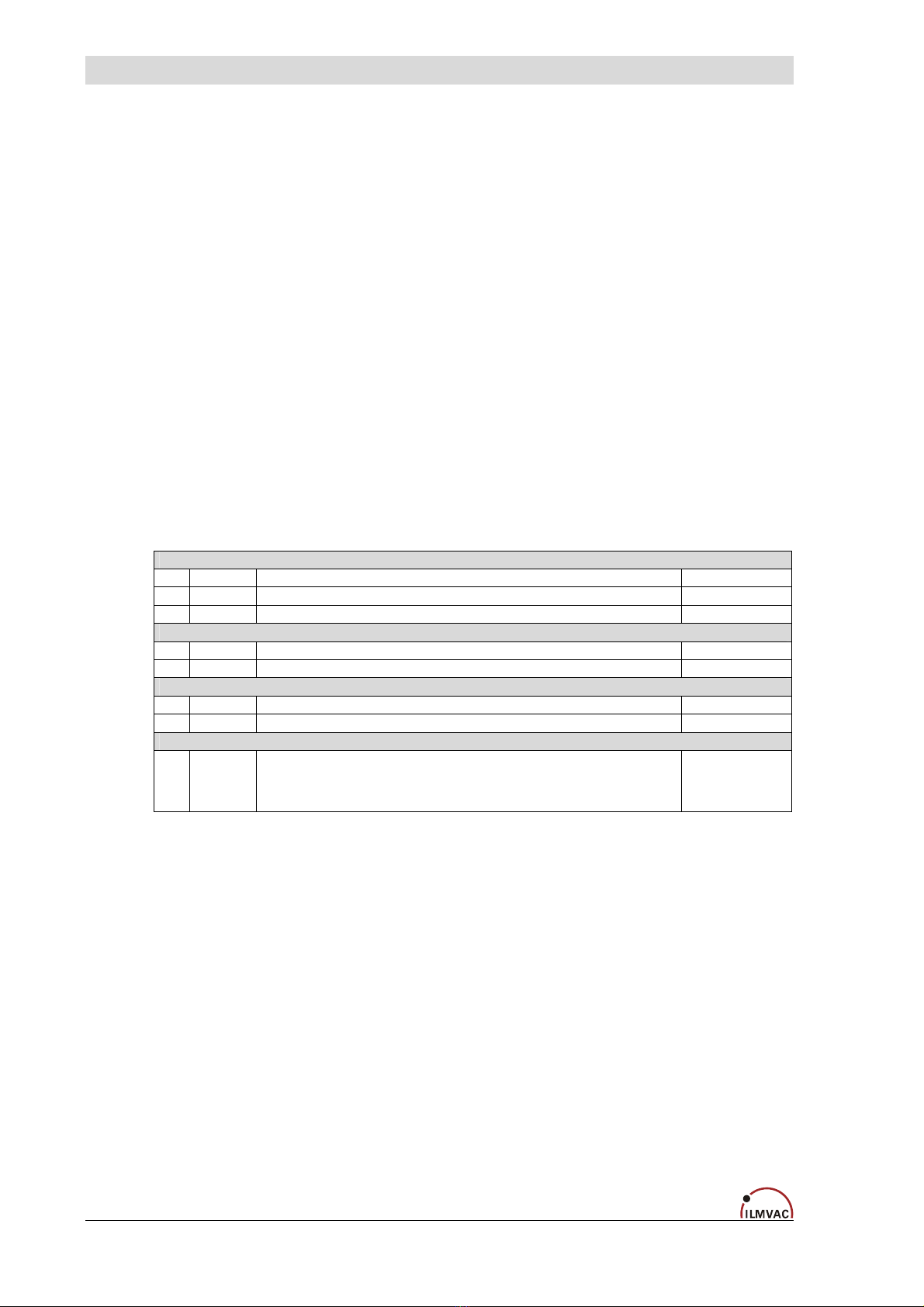
4.3 Device data
Parameter Data Unit
Pumping speed 50/60 Hz
at speed of 1500 rpm (DIN 28432) 1.1 / 1.2 m3/ h
Ultimate pressure at speed of 1500 rpm <2 mbar
Max. inlet pressure 1 bar
Max. outlet pressure 1 bar
Intake and pressure ports Hose nozzle for vacuum hose NW 8 -
Ambient temperature + 10 bis + 40 °C
Max. Operating gas temperature + 60 °C
Bearing maintenance-free -
Reference surface sound pressure level
DIN 45635 part 13 <44 dB (A)
Voltage / Frequency 90 – 240, 50/60
(generally with motor protection switch, switch and cable)
V - AC,
Hz
Power 0.83 kW
Operating mode S 1 -
Type of protection DIN EN 60529 IP 20 -
EC Direct current motor 24 V
Class of insulation (Motor) DIN EN 600034-1 F (160°C) -
Micro fuse (slow-acting) T 1 A
Dimensions (W/D/H) 250 / 260 / 435 mm
Weight 9.0 kg
Order number for LVS :
- without mains connection cable 113184 -
Order numbers for :
- Mains connection cable CEE 825885
- Mains connection cable UK 825878
- Mains connection cable CH 825877
- Mains connection cable US 825903
-
Vacuum Controller :
3 conductor interface -
10 Hz
12 Bit
+ 5 stabilized V
Sensor interface :
• Scan frequency
• Resolution ADC
• Power supply
• Sensor signal 0.5 to 4.5 (optionally also 0..5 V or 4..20 mA possible) V
Display digital; red, 9 mm high digits in mbar, torr or psi -
Switching accuracy / control accuracy ±1 digit
digital -
0; 24 V
12 W
Switching outputs :
• Voltage level
• Control power, single
• Control power, total 24 W
2
x
Switching outputs used :
• Ventilation valve
• Water valve x
-
analog -
0 to 10 V
Output analog:
• Voltage level
• Resolution DAC 8 Bit
Communication interfaces RS 232 , RS 485 (optional) -
Power consumption
Controller in normal operation max. 20 (depends upon the control power) W
Fuse (internal controller) 5 A
Sensor : integrated
Sensor type ceramic sensor -
Measuring range 1 - 1100 mbar
Measuring uncertainty ±2; FS mbar
Power pack : internal
Operating voltage 90 .. 264 V AC
Operating frequency 50 / 60 Hz
Output voltage 24 V DC
Output current 4 A
Output power 100 W
Connections :
IN/OUT : RS 232 SUB-D plug 9-pole -
OUT: Water valve Binder socket 4-pole, 24 V DC -
Connection : Inert gas integrated, Hose nozzle DN 4 -
OUT: mobile operating pad Binder socket 4-pole -
113184 15

Assembly and Installation
5 Assembly and Installation
5.1 Unpacking
Carefully unpack the laboratory-vacuum-system.
Check the system for:
• Transport damage,
• Conformity with the specifications of the supply contract (type, electrical supply data),
• Completeness of the delivery.
Please inform Ilmvac GmbH without delay if there are discrepancies between the delivery
and the contractually agreed scope of delivery, or if damage is detected.
– Please take note of the general terms of business of ILMVAC GmbH.
In case of a claim under warranty, the device must be returned in packaging that is
suitable for protecting it during transport.
5.2 Installation and Connection
• Set the laboratory-vacuum-system on a flat and horizontal surface.
• Remove the protective caps on the connections.
• Connect the suction connector of the LVS to your apparatus with vacuum hose DN8.
• Connect the cooling water tube to the emission condenser.
• The cooling water return flow must be unpressurized.
• Connect the air exhaust to the central air exhaust system.
• Connect the laboratory-vacuum-system to the power supply.
• Check that the connections are properly seated.
5.2.1 General instructions
Observe the basic safety instructions when using the LVS.
The pressure device regulation 97/23/EC must be observed if devices with an overpressure
of 0.5 bar or more are connected.
The pressures at the suction and pressure sides of the diaphragm pump at the time it is
switched on must correspond to the specifications of DIN 28432.
In order to avoid pumping speed losses, all the vacuum connecting hoses used should have
a large nominal diameter and should be laid out so that the lengths are as short as possible.
Avoid rigid connections. They must be assembled carefully in order to achieve a low leak ra-
te.
We recommend fitting non-return valves (order no. 720327) for applications with several
consumers.
The upstream separator on the suction-side serves to protect the diaphragm pump and the
vacuum sensor from condensates and mechanical contamination. It must be used for an ap-
plication. The level in the separator must be monitored and the separator emptied regularly.
The currently valid regulations must be observed when disposing of waste. The separator on
the suction-side can only be removed and emptied after the system has been vented.
16 113184
Assembly and Installation
The emission condenser enables a 100 per cent recovery of the solvents led through the
vacuum pump. Cooling takes place via the DN 8 hose nipples. Ensure that the outflow is
clear. The safety valve is located at the gas inlet. The rubber valve seal must be checked
for cracks at regular intervals and exchanged when necessary. The exhaust connection must
always be clear, and the exhaust can be led off through a DN 8 hose into a suitable evacua-
tion duct. There is common solvent reclamation for all the connected systems. Mixing media
must not lead to a hazard for persons, the environment of for the equipment.
The vacuum ducts must always be laid sloping downwards so that condensates can flow into
the relevant separators.
In case of soiling by solid matter, the pump heads must be opened and the entire interior
space, including valves and diaphragm, cleaned mechanically (see chapter 7.2.1).
5.3 Storage
The pumps are to be stored in a low-dust, interior room within the temperature range from
+ 5 to + 40 °C and at a relative air humidity < 90%.
Leave the protective elements on the suction and pressure ports. Another equally good pro-
tection may be used.
5.4 Scrap Disposal
CAUTION !
The laboratory-vacuum-systems must be disposed of in accordance with the
2002/96/EC guideline and the specific national regulations.
Contaminated pump systems must be decontaminated according to the laws.
113184 17
Operation
6 Operation
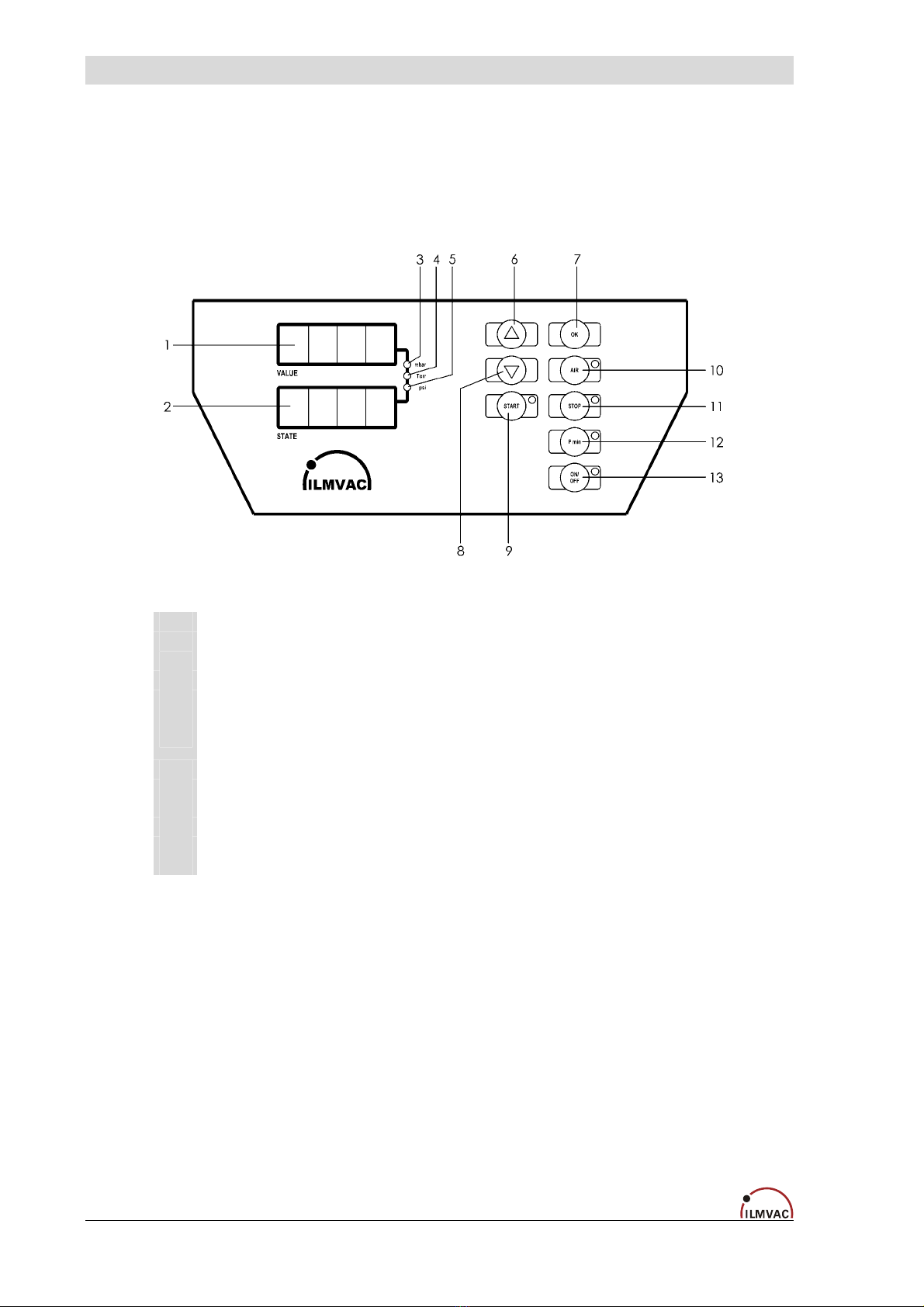
6.1 Control panel
1 VALUE: VALUE: 4 digit 7 segment LED display – Pressure value, parameter value
2 STATE: 4 digit 7 segment LED display – Mode, operating mode, type of parameter
3 mbar: Luminous spot = identification of the unit of measurement mbar (factory setting)
4 torr: Luminous spot = identification of the unit of measurement Torr
5 psi: Luminous spot = identification of the unit of measurement psi
6 UP: arrow key changes values (upwards)
7 OK: setting level – selection of the parameters to be set – activation of the setting values
Transfer of temporary values into the memory during operation
8 DOWN: arrow key changes values (downwards)
9 START: activation of a procedure
10 AIR: Venting
11 STOP: end of a procedure
12 P min Reduction of the pressure to a minimum
13 ON/OFF Separate switch off of the controller
Fig. 6 Control panel
6.1.1 Starting up
The Vacuum Controller is switched on by the rocker switch POWER located on the device.
The device is ready for operation after a short initializing routine, during which a signal tone
sounds and all light elements light up briefly.
18 113184

Operation
6.2 Operating modes of the Controller
Setting to different operating modes (see chapter 6.4.2)
Manual modeMode 1
Lowering the working pressure until the set pressure has been attained and held constant.
After switching on the power supply to the vacuum pump and controller, and selecting mode 1, the
process is started by pressing the start button. The pressure is reduced to the set pressure value PS
(mbar) 1), see Setting control parameters.
In this way, the pressure is held constant by two defined threshold values (set value, hysteresis). This
operating mode exemplifies the classical 2-point control. This control procedure is repeated until the
operator terminates operation (STOP key). The receptacle may be ventilated by pressing the AIR key.
The set value may also be changed during operation in manual mode by means of (↑,↓). This set
value is not stored, so the set value present at program start is retained. (see chapter 6.2.5)
"ecoflex" pump models work directly at the set pressure value.
Manual mode with settable pressure reductionMode 2
As in operating mode 1, but with an additional function for adapting the evacuation process to
processes in which the boiling point shifts (reduction of the concentration of the volatile com-
ponent).
After attaining the set pressure value PS, there is a further pressure reduction corresponding to the
set pressure value PL (1...1000 mbar) and a time tL (1...240 min) 2) which has to be defined previ-
ously. The maximum rate of change of pressure is limited to 1 mbar/s.
Mode 5 Automatic operation
Lowering the working pressure until a boiling point is found automatically (also with mixtures).
In the automatic operating modes, the controller continuously checks the course of the pumping out
curve (pressure change per unit time). It interprets significant deviations in the slope as the start of
vapour formation and defines this pressure point as a set value. That is, the controller treats the value
found in this way from now on in the same way as the set value in the previous modes. The sensitivity
of the controller can be set with parameter PA (a higher PA value for volatile substances and a lower
PA value for non-volatile substances, (see Setting control parameters)). After finding the pressure
point, the controller carries on working in mode 1.
In the case of certain solvent mixtures or deeply cooled condensates, the optimal boiling point is not
always found. In such cases, the distillation process may be further optimised by repeating with chan-
ged PA values. Maximum distillation speed can be achieved in this way, taking into account the cooler
capacity and the stability of the vaporization process (no frothing of the distillate).
Automatic operation with settable pressure reductionMode 6
As operating mode 5, and after the boiling point has been found, in order to get a further low-
ering of the working pressure corresponding to the set pressure value PL (mbar) and tL
(min) 2) .
CAUTION !
The vacuum controller is released for the application of modes 1, 2, 5 and 6.
The mode required is selected according to the work task and the connected periph-
eral equipment.
1) Corresponding to the set unit of measurement: mbar, Torr, psi
2) tL is displayed on the control panel in minutes, and in the "ILMVAC-Control" program in seconds.
113184 19
Operation
6.2.1 Selection, display of operating modes
After switching on, the desired operating mode can be set with the cursor keys ↑UP and ↓
DOWN. The current operating mode appears in the first position of the display and is acti-
vated with the START key (a "-" appears in the second position of the display). The STOP
key terminates the operating mode ("-" disappears) and the control is thus disabled.
The current control parameters can be brought into the display while the program is running
without interrupting the control sequence by pressing the START key for 3 seconds.
The code letter of the currently selected parameter appears in the STATE display field and
its associated value in the VALUE display field.
6.2.2 Setting / changing the control parameters at the controller
The configuration menu is used to set the control parameters. It may only be entered when
the control is inactive (control interrupted with the STOP key).
Press the OK button for three seconds. The mode code in the VALUE display field changes
to P. Select the setting parameter with the ↑UP and ↓DOWN buttons (see table below).
Only those parameters which have to be set for the selected mode are displayed. Key to the
code letters:
P Pressure settings in (<de> = set pressure unit mbar, torr or psi)
PS <de> Set value Modes 1, 2
PL <de> Amount of pressure reduction (Low pressure) Modes 2, 6
PA <de>/min threshold value for detecting the boiling point automatic mode Modes 5, 6
t Time setting
tL min Time for the pressure reduction (Low pressure) Modes 2, 6
tH min After-running time for the cooling water (H2O) Modes 1, 2, 5, 6
C Pressure sensor calibration
CH <de> at normal pressure 3) (High)
CL <de> at low pressure (Low) (at lowest possible pressure, e.g. 10 mbar)
F Frequency reduction in %, starting from the maximum operating frequency
FA % For determining the boiling point smoothly. Manufacturer recommendation
= 32 %.
Depending on the solvent, this value may have to be determined and
corrected iteratively.
Modes 5, 6
3) daily air pressure / barometric pressure
After selecting the parameter, confirm it with OK.
This display changes to "E".
Set the desired value with the↑UP and↓DOWN keys, confirm with OK, and repeat with the
other required parameters if necessary.
Press the STOP key to leave the setting menu.
The set values are stored after the setting menu has been left.
20 113184
Table of contents
Other Ilmvac Laboratory Equipment manuals


