Ilmvac biovac 106 User manual

Operation Manual
Safety Aspiration-System
Type biovac 106
112012
2008-04-04

We are constantly working on the further development of all our product types.
Reprinting or reproduction of this manual, including extracts, is not allowed without the prior written permission of
ILMVAC GmbH.
All rights under the copyright laws are expressly reserved by ILMVAC GmbH.
We reserve the right to make changes and amendments.
ILMVAC GmbH
Am Vogelherd 20
98693 Ilmenau, Germany
Telephone: +49 36 77 60 40
Fax: +49 36 77 60 41 10
E-mail: [email protected]
Internet : http://www.ilmvac.de
http://www.ilmvac.com

Contents
Contents
1Important Information.............................................................................................................4
1.1 General information ..................................................................................................................4
1.2 Target groups............................................................................................................................4
1.3 Intended Use.............................................................................................................................4
1.4 Use for an Unauthorized Purpose ............................................................................................4
1.5 Safety Devices ..........................................................................................................................5
1.6 Meaning of the Warning notes ..................................................................................................5
1.7 Product Standards, Safety Regulations....................................................................................5
2Basic Safety Instructions .......................................................................................................6
2.1 General information ..................................................................................................................6
2.2 Electricity...................................................................................................................................6
2.3 Mechanical System...................................................................................................................6
2.4 Hazardous Substances.............................................................................................................7
2.5 High Temperatures ...................................................................................................................7
3Description ..............................................................................................................................8
3.1 Design .......................................................................................................................................8
3.2 Principle of Operation ...............................................................................................................9
3.3 Areas of Application ..................................................................................................................9
3.4 Scope of Delivery:.....................................................................................................................9
3.5 Accessories...............................................................................................................................9
4Technical Data.......................................................................................................................10
4.1 Intake Pressure/Pumping Speed – Diagram ..........................................................................10
5Installation and Operation....................................................................................................11
5.1 Unpacking ...............................................................................................................................11
5.2 Installation and Connection.....................................................................................................11
5.2.1 Schematic representation of the connections.........................................................................12
5.3 Operation ................................................................................................................................12
5.4 Storage....................................................................................................................................13
5.5 Scrap Disposal ........................................................................................................................13
6Maintenance and Servicing..................................................................................................14
6.1 General Requirements............................................................................................................14
6.2 Maintenance of the aspiration-system ....................................................................................14
6.2.1 Disassembly............................................................................................................................14
6.2.2 Assembly.................................................................................................................................14
6.2.3 Test .........................................................................................................................................15
6.3 Maintenance of the diaphragm pump .....................................................................................15
6.4 Maintenance of other components .........................................................................................15
6.5 Damage Report.......................................................................................................................15
7Troubleshooting....................................................................................................................16
8Spare Parts Overview ...........................................................................................................17
8.1 Maintenance kit.......................................................................................................................17
8.2 Spare parts view .....................................................................................................................18
8.2.1 Spare parts list ........................................................................................................................19
Appendix
Operation Manual diaphragm pump MPC 054 Zp
112012 3

Important Information
1 Important Information
1.1 General information
The ILMVAC biovac 106 Safety Aspiration-System conforms to the
• 2006/95/EC Low Voltage Directive
• 2006/42/EC Machinery Directive
• 2004/108/EC Electromagnetic Compatibility Directive
The CE sign is located on the rating plate. Observe the binding national and local regulations
when fitting the system into installations.
Our products are sold worldwide and can therefore be equipped with the typical national
plugs and for the various voltages. You will find more information about the available system
models at Ilmvac GmbH.
1.2 Target groups
This Operating Manual is intended for the personnel planning, operating and maintaining the
biovac 106 Safety Aspiration-System. This group of people includes:
• Designers and fitters of vacuum apparatus,
• Employees working on commercial laboratory and industrial vacuum technology applica-
tions and
• Service personnel for safety aspiration-system.
The operating and maintaining personnel of the Safety Aspiration-System must have the
technical competence required to perform the work that has to be done.
The user must authorize the operating personnel to do the work that has to be done.
The personnel must have read and understood the complete Operating Manual before using
the Safety Aspiration-System.
The Operating Manual must be kept at the place of use and be available to the personnel
when required.
1.3 Intended Use
• The layout of the Safety Aspiration-System must be appropriate for the conditions of use.
The user bears the sole responsibility for this.
• The Safety Aspiration-System may only be operated under the conditions stated
- in the "Technical Data" section,
- on the rating plate, and
- in the technical specification for the order concerned.
• The Safety Aspiration System has an integrated, highly chemical-resistant diaphragm
pump. It is used in chemical, biological and medical applications to extract non-explosive
liquid residues safely and precisely.
1.4 Use for an Unauthorized Purpose
It is forbidden to use the pump for applications deviating from the technical data stated on
the type plate or the conditions stated in the supply contract, or to operate it with missing or
defective protective devices.
4 112012

Important Information
1.5 Safety Devices
Measures such as the following are for the safety of the operating personnel:
• operating mode S1 (with grounding connector)
• integrated fuse in the vacuum pump
• closed housing
• intact collecting tank
• insertion of a particle filter suitable for the work task
1.6 Meaning of the Warning notes
Take note of the warning notes. They are in the following box:
CAUTION / WARNING !
Hazard which may lead to serious injuries or material damage.
1.7 Product Standards, Safety Regulations
The ILMVAC Safety Aspiration-System fulfils the following product standards:
DIN EN 292-1, DIN EN 292-2 Safety of machines, basic terminology
DIN EN 1012-2 Compressors and vacuum pumps
DIN EN 60204-1 Electrical equipment of machines
EN 50110-1 (DIN VDE 0105-100) Operation of electrical installations
EN 61010-1 Safety for laboratory devices
EN 50081-1-2 Electromagnetic compatibility (EMC)
Generic specification - Interference resistance
for residential, business and industrial areas, and small businesses
EN 50082-1-2 Electromagnetic compatibility (EMC)
Generic specification - Interference emission
for residential, business and industrial areas, and small businesses
EN 55014 Radio disturbance characteristics of electrical equipment and
systems
EN 61000-3-2/3 Electromagnetic compatibility (EMC)
Directive 2006/42/EC Law and Administration Regulations relating to Machinery
Directive 2002/95/EC RoHS Restriction of use of certain hazardous substances
The following additional safety regulations apply in the FR Germany:
BGV A2 Electrical equipment and operating materials
VBG 5 Power-driven machines
BGR 120 Guidelines for laboratories
BGI 798 BG hazard assessment in the laboratory
Observe the standards and regulations applying in your country when you use the safety as-
piration-systems.
112012 5

Basic Safety Instructions
2 Basic Safety Instructions
2.1 General information
WARNING !
Warning notices must be observed. Disregarding them may lead to damage to health
and property.
The biovac 106 safety aspiration-system must be operated by personnel who can detect im-
pending dangers and take action to prevent them from materialising.
The manufacturer or authorized authorised workshops will only service or maintain the safety
aspiration-system if it is accompanied by a fully completed damage report. Precise informa-
tion about the contamination (also negative information if necessary) and thorough cleaning
of the system are legally binding parts of the contract.
Contaminated safety aspiration-system and their individual parts must be disposed of in ac-
cordance with the legal regulations.
The local regulations apply in foreign countries.
2.2 Electricity
The safety aspiration-systems are supplied for operating mode S1. Please note that the test-
ing must be repeated in accordance with DIN EN 0105, DIN EN 0702 and BGV A2 in case of
portable devices.
The local regulations apply in foreign countries.
Please note the following when connecting to the electrical power supply system:
• The electrical power supply system must have a protective connector according to DIN
VDE 0100-410 (IEC 60364-4-41).
• The protective connector must not have any breaks.
• The connecting cable must not be damaged.
2.3 Mechanical System
Improper use can lead to injuries or material damage. Observe the following instructions:
• Only operate the safety aspiration-system with hoses of the specified dimensions.
• Solid particles in the pumping medium impair the pumping action and can lead to dam-
age. Prevent their penetrating into the pump.
• Hazardous substances must be separated out as far as this is technically possible before
they reach the pump.
• External mechanical stresses and vibrations must not be transmitted to the system. Only
use a flexible laboratory hose for connecting the safety aspiration-system.
• The overpressure generated at the pressure port must not exceed 1 bar.
• The pump must not be used to pump liquids.
• Set the safety aspiration-system on a flat and horizontal surface.
• Do not close the space beyond the bottom of the device in order to enable the pump to
cool.
6 112012

Basic Safety Instructions
2.4 Hazardous Substances
The responsibility for using the biovac 106 safety aspiration-system rests with the operator.
Hazardous substances in the gases to be pumped can cause personal injuries and property
damage. Pay attention to the warning notices for handling hazardous substances.
The local regulations apply in foreign countries.
Explosive gases
The safety aspiration-system is not certified according to ATEX guidelines 94/9/EC.
The system operator is obliged to comply with the ATEX 137 guidelines 99/92/EC when us-
ing the pump within and for danger areas.
Aggressive gases
An MP series diaphragm pump is used for extracting vapours and aggressive gases.
The warranty shall lapse if the safety aspiration-system is used with diaphragm pumps from
other manufacturers.
Poisonous gases
Use a separator when pumping poisonous or harmful gases. Prevent such substances from
leaking out of the appliance or pump. Treat these substances according to the applicable
environmental protection regulations.
The diaphragm pump, control valves and hose lines can be damaged by poisonous or ag-
gressive gases.
Test the strength and leak-tightness of the connecting lines and the connected apparatus.
Prevent environmental poisons, e.g. mercury, getting into the diaphragm pumps.
Fulfil the requirements, for example:
• German Hazardous Substances Regulation (GefStoffV) of 23. December 2004
• Regulations 2006/121/EC (classification, packaging and identification of hazardous sub-
stances),
• Manufacturer's safety data sheets on hazardous substances.
2.5 High Temperatures
The diaphragm pump may heat up as a result of the temperature of the gas being pumped
and through compression heat.
Prevent the following maximum permissible temperatures from being exceeded.
• + 40 °C for the environment and
• + 40 °C for the medium to be pumped.
The motor for single phase alternating current is protected against overload by a fine-wire
fuse.
112012 7
Description
3 Description
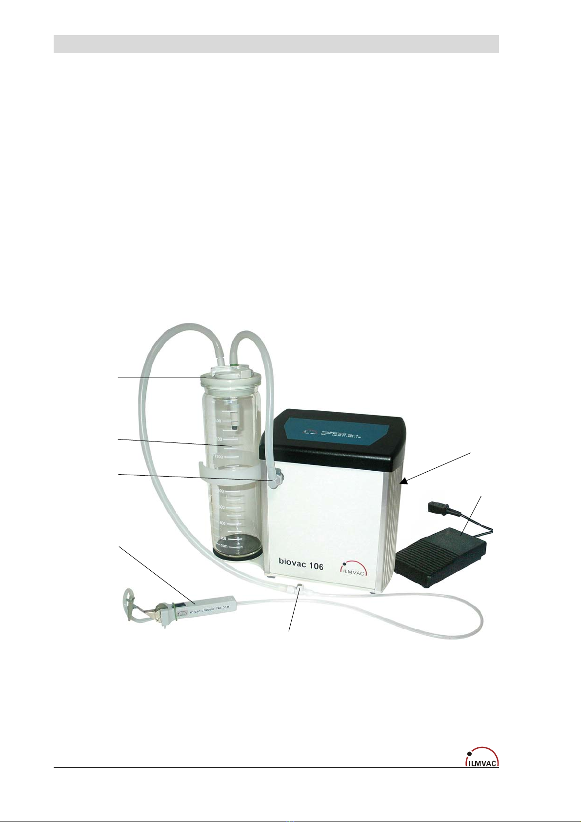
3.1 Design
A filter holder for a diaphragm filter is integrated between drip pan (1) and diaphragm pump
(2). A diaphragm filter up to a filter fineness of 0.22 µm can be inserted into this holder by the
user as required for the work to be done. According to the filter fineness used, it is possible
to achieve different types of filtration, enabling, among other uses, the handling of bacteria
and viruses.
The sealing (3) at the head of the drip pan consists of a formed gasket.
The connections to the diaphragm pump are established by using quick-fitting couplings (4),
which are provided with a two-side stop valve each on both sides.
The chemical-resistant diaphragm pump used has a long useful life and at the device switch
one switches on. If necessary switching on can take place also via foot switch (5) (accesso-
ries optional).
Drip pan (1) and handpiece (pipette holder) (6) are connected to one another using a hose.
The built-in hose coupling (7), which seals both sides, can be used to shut off the connec-
tion.
The user can insert suitable pipetting tips into the receptacle of the handpiece (pipette
holder).
(7)
(5)
(2)
(3)
(1)
(4)
(6)
Fig. 1 Safety Aspiration-System “biovac 106”
8 112012
Description
3.2 Principle of Operation
Excess fluids can be removed easily at a fine dosage from slides, petri dishes, containers
with cell cultures, etc., by using different pipettes or glass tips which are inserted into the pi-
petting holder (6).
The big integrated drip pan with a built-in float valve will close automatically as soon as the
maximum level is reached.
3.3 Areas of Application
The ILMVAC biovac 106 Safety Aspiration-System is intended for:
• the safe and precise extraction of liquid and non-explosive excess fluids
• Use in the chemical, biological and medical areas
• Generating a vacuum down to an ultimate pressure < 150 mbar.
3.4 Scope of Delivery:
The scope of delivery is specified in the supply contract.
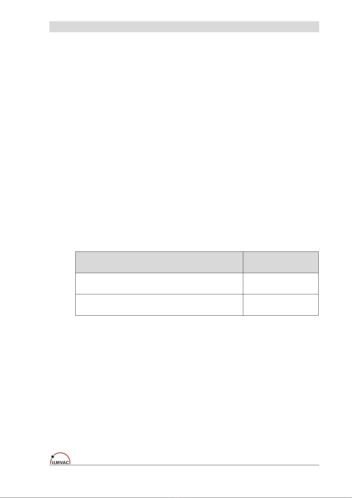
3.5 Accessories
Designation Order no.
Foot switch complete 112529
Bacteria filter for secret glass container (drip pan) 828840-2
112012 9

Technical Data
4 Technical Data
Parameter Unit Data
m3/ h 0.72Pumping speed
DIN 28432 with speed of 1500 rpm l / min 12 /16
Ultimate pressure mbar <150
Maximum inlet pressure bar 1
Maximum outlet pressure bar 1
Inlet connection 1 Hand piece (pipetting holder)
Exhaust connection - Hose nozzle
for hose inside diameter 8 mm
Receptacle
with float valve and non-woven filter holder - 2 litres, autoclave resistant
(option 1 litre)
Ambient temperature °C + 10 to + 40
Medium temperature °C + 40
Bearing - maintenance-free
Reference surface sound pressure level
DIN 45635 part 13 dB (A) <45
Voltage AC asynchronous motor V, Hz 115 / 230
Frequency Hz 50 / 60
Power W 0.45
Fine fuse A F 3.15
Operating mode - S 1
Type of protection (motor)
as per DIN EN 60529 - IP 40
Class of insulation
as per DIN EN 600034-1 - F (160°C)
Dimensions (W/ D/ H) (without hose) mm 357 / 145 / 277
Weight kg 8
Order numbers for :
- Mains connection cable CEE 825885
- Mains connection cable UK 825875
- Mains connection cable CH 825877
- Mains connection cable US 825903
- biovac 106 (without mains connection cable)
-
112012
4.1 Intake Pressure/Pumping Speed – Diagram
Fig. 2 Intake pressure pumping speed
10 112012

Installation and Operation
5 Installation and Operation
5.1 Unpacking
Carefully unpack the biovac 106 Safety Aspiration-System.
Check for:
• Transport damage,
• Conformity with the specifications of the supply contract (type, electrical supply data),
• Completeness of the delivery.
Please inform Ilmvac GmbH without delay if there are discrepancies between the delivery
and the contractually agreed scope of delivery, or if damage is detected.
Please take note of the General Terms for Delivery and Payment of ILMVAC GmbH.
In case of a claim under warranty, the device must be returned in packaging that is
suitable for protecting it during transport.
5.2 Installation and Connection
1. Set the safety aspiration-system on a
flat and horizontal surface.
2. Connect the handpiece (pipette holder)
to the suction line (1).
3. Connect the suction pipe to the
building ventilation system (2).
4. If required, connect the foot switch
(accessories optional) to the socket (3)
provided on the unit.
5. Set the mode selector switch (4) to
"Hand" or "Foot" (see option, point 5).
6. Voltage selector 115/230 V (5)
Label on device:
7. Connect the safety aspiration pump to
the power supply (6).
8. Switch on the unit's main switch (7).
Fig. 3 Safety Aspiration-System biovac 106
rear side - connections
112012 11

Installation and Operation
5.2.1 Schematic representation of the connections
1 - Handpiece (pipette holder)
1a - Meterable extraction into the suction hose
1b - Key valve for aspiration into the tank
2 - Double-sided coupling with valve
3 - Separator
4 - Float valve
5 - Filter
6 - Single-sided coupling with valve
7 - Diaphragm pump
8 - Exhaust connection
Fig. 4 Schematic representation of the connections
5.3 Operation
CAUTION!
Before the device is switched on, the voltage selector must be set with a screwdriver
to the voltage of the local power supply, either 115 or 220 V (+/-10%).
• Set mode selector switch to "Hand" or "Foot".
• The safety aspiration system is switched on and off at the operating switch (illuminated
rocker switch).
• Press the foot switch button when using the foot option.
• A low air pressure is generated in the reservoir.
• The liquid is extracted into the tank with the handpiece (pipette holder) by turning the
wheel and then pressing the button.
• For the safety of the user, a ∅55 mm membrane filter suitable for the requirements and
work task must be inserted into the filter casing.
CAUTION !
After using it, disconnect the handpiece (pipette holder) from the suction line at the
coupling. To avoid any sticking, make sure to flush the hose thoroughly after use!
12 112012

Installation and Operation
CAUTION!
Observe the basic safety instructions when using the safety aspiration-system!
5.4 Storage
The pumps are to be stored in a low-dust, interior room within the temperature range from
+ 5 to + 40 °C and at a relative air humidity < 90%.
Leave the protective elements on the intake and pressure ports. Another equally good pro-
tection may be used.
5.5 Scrap Disposal
CAUTION !
The safety aspiration-systems must be disposed of in accordance with the
2002/96/EC guideline and the specific national regulations.
Contaminated pump systems must be decontaminated according to the laws.
The user is responsible for disposing of the products extracted and decontaminating the col-
lecting tank and hoses.
If the collecting tank is under underpressure while disposing of and decontaminating the con-
tents, this can be compensated for by placing the coupling on a flat surface.
112012 13
Maintenance and Servicing
6 Maintenance and Servicing
6.1 General Requirements
Repairs of the ILMVAC biovac 106 safety aspiration-system may only be performed by the
manufacturer or authorized workshops. The prerequisites are a complete and factually cor-
rect damage report, and a clean and, if necessary, a decontaminate device.
Send in defective devices for repair either to the manufacturer or to an authorized workshop.
The information about the contamination or thorough cleaning are legally binding parts of the
contract.
WARNING !
When repairing contaminated units, be sure to observe the applicable user specifica-
tions regarding decontamination as required.
Provide full information about the type of contamination and the used materials and
clean the pump thoroughly before handing it over to third parties.
The operator may perform maintenance work to the extent indicated below:
6.2 Maintenance of the aspiration-system
6.2.1 Disassembly
• Disconnect the power supply and ensure that it cannot be switched on again.
• Disconnect the hose connections at the couplings.
• To empty, clean and decontaminate the collecting tank, lift it up out of the holder of the
aspiration system.
• Unscrew from below the four inner screws on the device.
• Unscrew the suction and exhaust connections.
• Lift the hood off.
You can now start maintenance work as described in the appendix to the "Diaphragm
Pump" operating instructions.
WARNING !
Wear protective gloves or protective clothing if necessary !
Do not clean with compressed air !
6.2.2 Assembly
Assembly takes place in reverse sequence. Use care when carrying out these activities, and
check for the proper fit of the couplings.
14 112012

Maintenance and Servicing
6.2.3 Test
Connect a vacuum measuring device to the intake port and check the ultimate pressure. If
the device is working properly, then the figure stated in the technical data must be attained
within a maximum of one minute.
6.3 Maintenance of the diaphragm pump
• see the attached "Diaphragm pumps" operating manual
6.4 Maintenance of other components
• Check that the glass drip pan is undamaged, cleaned and if necessary replace.
• Empty the drip pan in a timely manner
(Observe all disposal specifications as applicable to hazardous substances!)
• Check screw connections for tightness and tightened when necessary.
• Check vacuum hoses for leaks and, if necessary, replace them.
• Check for leaks and, if necessary, replace the formed gasket located at the head piece of
the drip pan
• Change the membrane filter at regular, defined intervals.
• Test performance of the quick-fitting couplings with shut-off valves
WARNING !
Only perform the work that is described here, and that which is permitted to be done
by the user.
All other maintenance and service work may only be performed by the manufacturer
or a dealer authorized by him.
Beware of the device parts being possibly contaminated by hazardous substances.
Please observe the applicable disposal regulations !
Wear protective clothing if there is contamination.
6.5 Damage Report
You find the form of the damage report to the Download on our web page
http://www.ilmvac.de and/or http://www.ilmvac.com in the menu "service" and "Downloads".
If you should not have an entrance to the Internet, you can request the form also gladly with
us, company Ilmvac GmbH.
WARNING !
Incomplete or incorrectly completed damage reports may endanger the service per-
sonnel!
Give full information in the damage report, in particular regarding a possible con-
taminating.
112012 15
Troubleshooting
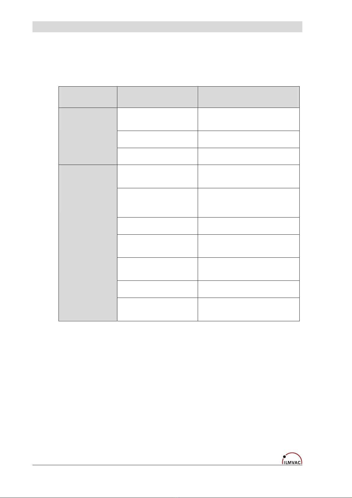
7 Troubleshooting
During the warranty period, intervention in the safety aspiration-system and accessory
components may only be made by ILMVAC GmbH and or authorised workshops.
Trouble Cause Remedy
No power supply to the motor Electrical system to be checked
by a qualified electrician.
Motor defective Exchange by service shop.
Diaphragm pump
does not start
Pump body defective Repair by service shop.
Connected apparatus leaks,
connecting elements leak
Identify and seal the leak, replace the
seals and hoses if necessary.
Diaphragm pump leaks
(pipes or hoses)
Check the hose connections between
the pump heads, replace the hoses and
screwed clamping rings if necessary.
Pump head Repair by service shop.
Diaphragm defective Repair by the service workshop
or the user.
Valves are dirty Clean condensates and foreign
objects out of the valves.
Valves defective Replace valves.
The diaphragm
pump does not
generate a
vacuum or only
an inadequate
one.
Diaphragm pump is dirty Cleaning by the service workshop
or the user.
16 112012
Spare Parts Overview
8 Spare Parts Overview
The spare parts list contains all the spare parts and all the information necessary for order-
ing.
When ordering, please quote the description, quantity, serial number and order number!
CAUTION !
Ilmvac is not liable for any damage caused by the installation of any parts not sup-
plied by the manufacturer.
8.1 Maintenance kit
Designation Order no.
Maintenance kit 402045
The maintenance kit consists of:
Designation Piece Order no.
O-ring ø 25 x 2 4 829250-1
O-ring ø 8 x 2 2 829210-3
Valve 4 400656
Formed diaphragm 2 828929-1
112012 17

Spare Parts Overview
8.2 Spare parts view
Fig. 5 Exploded view – biovac 106
18 112012
Spare Parts Overview
8.2.1 Spare parts list
Item no. Designation Piece Order no.
1 Casing cover 1 112556
2 Casing 1 112557-03
3 Switch panel 1 400947-03
4 Aluminium profile 1 400950-05
5 Aluminium profile 1 400950-06
6 Aluminium profile 2 400950
7 Foot plate 1 400937-03
8 Pump head 2 400898-04
9 Valve 4 400656
10 O-ring Ø 25 x 2 4 829250-1
11 Connection head 1 400899-05
12 Connection head 1 400899-06
13 Pressure plate 2 400935
14 O-ring Ø 8 x 2 2 829210-3
15 O-ring Ø 12 x 2 1 829217-3
16 Distributor PP, G 1/8“ – 2 x G 1/8“ L 1 400921
17 Hose nozzle PP, G 1/8“ 1 710797
18 Threaded elbow joint PVDF, 8 – 1/8“ 3 829936-1
19 Straight threaded joint with seal edge PVDF, 8 – 1/8“ 1 829919
20 Quick release coupling PP, NW 7.2 mm – ¼“ – 6.4 mm 1 829996-2
21 Angle with hose connector PP, NW 7.2 mm – ¼“ – 6.4 mm 1 829996-1
22 One-coil transformer UI 48/17 1 825702
23 Time controlling VAPU 0003 1 825681
24 Motor operating condenser 2.5 µF 2 825459
25 Combination connector 1 825274-4
26 Fine-wire fuse F 3.15 A 1 825391-1
27 Rocker switch 4 (1) A green 1 825186-3
28 Rocker switch 16 (4) A green 1 825186-1
29 Voltage voter 115/230 V 1 825187
30 Socket for non-heating apparatus 1 825274-5
31 Casing foot 5 829112
32 Rubber plate 1 112547-02
33 Guard ring 1 112561
34 Collecting tank (secret glass container, 2 litres) 1 828840
35 Collecting tank cover (secret glass container, 2 litres) 1 828840-1
36 Silicone hose inside Ø 6 x wall thickness 3 mm
(1 x 1.2 m and 1 x 0.3 m) 1.5 m 828374
37 Vacuum hose PTFE, 8 / 6x1 mm 0.1 m 828331
38 Coupling piece (aperture 3.2 mm for hose inside Ø 6.4 mm) 1 829157-1
39 Handpiece (pipette holder) 1 112524
- *) Basic pump complete (consisting of position: 40 - 52) 1 400943-01
40 Intermediate plate 1 400948
41 Pump casing 1 400944
42 Rubber element 4 400916
43 Cylinder 2 400914
44 Formed diaphragm 2 828929-1
45 Insulating washer 1 400893-04
46 Condenser motor 1 826395-02
47 Mass balance 1 400945
- Drive 1 - complete (consisting of position: 48 – 50) 2 400919
48 Piston rod with ball bearing 1 400892-01
49 Eccentric 1 400915
50 Ball bearing 1 824963-1
- Drive 2 - complete (consisting of position: 51 - 52) 1 400919-01
51 Piston rod with ball bearing 1 400892-01
52 Eccentric 1 400915
*) The "basic pump" module (pos.: 40 – 52) can only be supplied complete under order number 400943-01 and/or
400858-01.
112012 19
Table of contents


