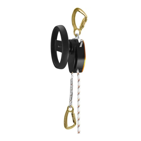
SKYLOTEC DEUS 3300 User manual

GEBRAUCHSANLEITUNG
GB
DE
Instructions for use
Gebrauchsanleitung
© SKYLOTEC
MAT-BA-0174-00
Stand 01.04.2019
SKYLOTEC DEUS 3300
SKYLOTEC DEUS 3700
PSA-VO (EU) 2016/425
0123
SKYLOTEC GmbH
Im Mühlengrund 6-8
56566 Neuwied · Germany
Fon +49 (0)2631/9680-0
Fax +49 (0)2631/9680-80
Mail [email protected]
Web www.skylotec.com

2
GB Instructions for use
Explanation ........................................................................................................Page 3-30
DE Gebrauchsanleitung
Erklärung...........................................................................................................Seite 31-58
Information (Note instruction)/
Informationen (Anleitung beachten)

3
NFPA CERTIFICATION
DEUS 3300 and 3700
DESCENT CONTROLLED DEVICE
Meets NFPA 1983 (2017 Edition)
Auxiliary Equipment Requirements, Life Safety
Equipment for Emergency Services
Escape “E”
Certied by TÜV Süd Product Service GmbH,
Ridlerstr. 65, 80339 München
TO BE COMPLIANT WITH NFPA 1983, THE FOLLOWING
ADDITIONAL COMPONENTS MUST BE USED IN
CONJUNCTION WITH THIS DEUS 3300 DESCENT
CONTROL DEVICE: Pelican rope A2TT-7.5 (7,5mm) or
A2W-7.5 (7,5mm).
TO BE COMPLIANT WITH NFPA 1983, THE FOLLOWING
ADDITIONAL COMPONENTS MUST BE USED IN
CONJUNCTION WITH THIS DEUS 3700 DESCENT
CONTROL DEVICE: Pelican rope A2W-8.0 (8,0mm).
ANSI TESTING
DEUS 3700
CONTROLLED DESCENT DEVICE
Use with A2W-8.0mm Rope
Meets ANSI/ASSE Z359.4 (2013 Edition)
Assisted-Rescue and Self-Rescue Systems,
Subsystems and Components
Multiple UseTested by TÜV Süd Product Service
GmbH, Ridlerstr. 65, 80339 München
CSA CERTIFICATION
DEUS 3700
CONTROLLED DESCENT DEVICE
Meets CSA Z259.2.3 (2012 Edition)
Safety Standard for Descent Devices
Type 1, Class B
Certied by CSA Group, Toronto, Canada
EN CERTIFICATION
DEUS 3700
CONTROLLED DESCENT DEVICE
Use with A2W-8.0mm Rope
In accordance with EN341 (2011 Edition)
and PPE Directive 89/686/EEC
Class 1B
Certied by TÜV Süd Product Service GmbH,
Ridlerstr. 65, 80339 München
Keep this Instruction Manual as part of a permanent
record that includes the usage and inspection history for
the equipment. Refer to the Instruction Manual before and
after each use. If the instructions are not followed, the user
could suffer serious injury or death. Additional information
regarding auxiliary equipment can be found in NFPA 1500,
Standard on Fire Department Occupational Safety and
Health Program, and NFPA 1983, Standard on Life Safety
Rope and Equipment for emergency services, 2017 Edition
THIS DEUS 3300 DESCENT CONTROL DEVICE HAS
PASSED THE MANNER OF FUNCTION AND HOLDING
LOAD TESTS USING THE FOLLOWING ROPE:
- Pelican Escape Rope; A2W-7.5L; ø7.5mm; - Pelican Fire
Escape Rope; A2TT-7.5T; ø7.5mm
THIS DEUS 3700 DESCENT CONTROL DEVICE HAS
PASSED THE MANNER OF FUNCTION AND HOLDING
LOAD TESTS USING THE FOLLOWING ROPE:
- Pelican Escape Rope; A2W-8.0 (8,0mm).
0123
Before using this equipment, you must:
• Read and understand this Instruction Manual.
• Get specic training in its proper use.
• Become acquainted with its capabilities and limitations.
• Understand and accept the risks involved.
Activities involving the use of this equipment are
inherently dangerous. You are responsible for
your own actions and decisions.
FAILURE TO HEED
ANY OF THESE
WARNINGS MAY
RESULT IN SEVERE
INJURY OR DEATH.
WARNING

4
• A SKYLOTEC DEUS 3000 Series controlled
descent device is only part of a complete
rescue system.
• All SKYLOTEC DEUS 3000 Series controlled
descent devices have load limitations.
• In life threatening situations the SKYLOTEC
DEUS 3000 Series controlled descent devices
may be used for two person descent.
• Make sure components of your complete
rescue system are compatible.
• Avoid impact loading of your rescue system.
• Pay special attention when attaching
connectors and when selecting an anchorage.
• Always wear appropriate gloves when using
DEUS controlled descent systems.
• Avoid descending into electrical, thermal,
chemical and other hazards.
• Avoid using SKYLOTEC controlled descent
devices around moving machinery.
• All SKYLOTEC DEUS 3000 Series controlled
descent devices and DEUS ropes must be
inspected before and after each use.
• Inspection must be carried out by a competent
person. (Please see page 26 for the DEUS
Equipment Usage Log.)
• Read the Use and Warranty information of this
Instruction Manual. (Please see page 27-28.)
SKYLOTEC reserves the right to change the
specications, performance and functionality of its
products at any time without prior notice.
1. SPECIAL NOTICES
• Understand and comply – it is the authorized
person’s and employer’s responsibility to strictly
conform to the following warnings:
– Provide each user with a copy of instructions
– Be aware of regulations
– Use only as specied – do not alter
– User assumes risks of failure to follow
instructions
– Remove immediately from service if
equipment fails to pass inspection
– Be aware of and comply with limitation of
user weight
– Be aware of and comply with limitation of
height of use
– Ensure that rope length exceeds the
required descent hight
– Ensure that all users are trained on
proper use, care and maintenance of this
equipment.
• Inspect and maintain equipment
• Train and manage persons at height
• Develop a rescue plan
• Continuously assess risks
2. RESPONSIBILITIES OF THE USER
GB Instruction for use

5
Congratulations on your selection of a
DEUS 3000 Series controlled descent device.
DEUS 3000 Series devices represent the most
technically advanced, controlled descent devices
in the world.
SKYLOTEC DEUS 3000 Series controlled
descent devices have four independent brakes for
maximum control, versatility and safety:
1) A disk actuated drum brake operated with the
control dial allows you to “stop” or “go” hands
free
2) The “always-active” centrifugal brake
3) The self-adjusting hands-free gure eight
brake provides redundant security
4) Manual rope tailing provides precise control.
Rope runs through SKYLOTEC DEUS 3000
Series controlled descent devices in either
direction. This makes it possible to rescue multiple
people, after each other.
SKYLOTEC DEUS 3000 Series controlled
descent devices are designed for repeated use,
which makes them ideal for training.
Intended Use
IMPORTANT: SKYLOTEC DEUS 3000 Series
controlled descent devices are designed for
use by professionals. The proper use of these
devices are inherently risky. They should only
be used by someone who has been property
trained and medically t. For more information
on training, contact SKYLOTEC. These devices
must not be used for play, and must not be used
by anyone who has not been trained, as it may
place the user at risk of serious injury or death.
IMPORTANT: Each SKYLOTEC controlled
descent device model is certied for use ONLY
with specic SKYLOTEC-approved ropes – do
not experiment with or use any other ropes. The
internal brake systems of each model have been
calibrated with the particular features of specic
ropes. Use of any other rope risks serious injury.
IMPORTANT: All rescue training from heights
should be done using a backup system. The
DEUS 7300 controlled descent device is
recommended by SKYLOTEC.
IMPORTANT: During rescue training, there
should be an additional rescue kit readily
available and located nearby that is not part of
the equipment being used for the training.
This Instruction Manual
This manual provides care and use instructions
for SKYLOTEC DEUS 3000 Series controlled
descent devices. Updates and additional
information may be found at www.skylotec.com.
This manual mentions but does not provide care
and use instructions for other items of equipment
that are essential parts of a vertical rescue
system. You should consult the specic instruction
manuals provided with each component of your
vertical rescue system to know how to safely
use that equipment, and the limitations of that
equipment.
This manual is intended as a reference and
a supplement to training. It does not replace
training, which is required for proper use of these
devices.
Although we diligently try to update product
specications in literature and at the website
in a timely manner, we cannot be responsible
for product or specication changes and
typographical errors.
Technical Assistance Contact Information
SKYLOTEC GmbH
Im Mühlengrund 6-8
56566 Neuwied · Germany
Mail [email protected]
Web www.skylotec.com
3. INTRODUCTION

6
4. DESCRIPTIONS OF THE PARTS OF A
VERTICAL RESCUE SYSTEM
A vertical rescue system consists of six
interdependent parts: 1) anchorage, 2) anchorage
connector, 3) rope, 4) controlled descent device,
5) connectors, and 6) harness. To conduct a
rescue after a fall, an additional part – a rescue
transfer unit – is also required. The system is only
as strong as the weakest part in the system. It is
the responsibility of the user to make sure he or
she understands all of the parts in the system and
how to use those parts.
In this manual, the term “controlled descent
device” is used to refer to a piece of hardware,
like one of the devices in the DEUS 3000 Series,
that is used to control vertical descent during an
escape or rescue. A “controlled descent device”
is part of a “vertical rescue system.” The term
“vertical rescue system” is used to describe the
system that includes all of the parts listed in the
previous paragraph.
WARNING: SKYLOTEC has carefully selected
each component of our escape and rescue
kits to work in conjunction with SKYLOTEC
descent devices for optimal efciency and safety.
Substituting any of these components may result
in injury or death. Anchorage – The anchorage
needs to be solid, unmovable, unyielding, and
unbreakable. Professionals who work at height
usually rely on pre-planned anchorages rated
to support specic maximum loads, depending
on the standard followed. For EN, the anchor
point must comply with EN 795, be above the
userwithstand at least 12kN. For ANSI, the anchor
must comply with ANSI Z359.1 and withstand
22.2 kN. Selection of an appropriate anchorage
is critical to performing a safe escape or rescue
descent and requires considerable training.
Anchorage connector – The anchorage
connector connects the vertical rescue system
to the anchorage. Always select an appropriate
anchorage connector. Ensure that the connection
between the anchorage and the descender
does not create obstacles that could impede
the descent. SKYLOTEC DEUS 3000 Series
Controlled Descent Devices –
Carabiner hole
Euler post
Back cover
hinge
Back cover
Carabiner hole
Sliding
Cam
Euler post
Drive wheel
stabilizer triangle
Drive wheel
Sticker showing
date of next
inspection of the
product
Back cover stop
Rope inlet/exit Rope inlet/exit
Anvil
Carabiner hole
Carabiner hole
Back cover
Control dial
Sliding cam access points
Back cover hinge
Back cover stop
Parts of a 3000 Series
controlled descent device

7
Controlled descent devices control the movement
of rope during descent or positioning. The
purpose of DEUS 3000 Series controlled descent
devices is to control the movement of rope either
automatically (hands free) or manually using
four independent brakes. The diagrams beneath
show the various parts of a DEUS 3000 Series
controlled descent device.
Connectors – Connectors can be either hardware
like carabiners or software like webbing and rope.
The purpose of connectors is to link together the
various parts of the system. A vertical rescue
system typically requires at least two connectors:
one to connect the person to the system, and one
to connect the system to a suitable anchorage
point. Connectors must comply with EN 362, ANSI
Z359.12, CSA, and NFPA 1983:2017. Only use of
connectors with a self closing and locking gate are
permitted.
Harness – The harness is what connects you
to the vertical rescue system. The purpose of
the harness is to secure you to the system and
safely and comfortably distribute load during
descent. Your employer will determine which
harness is appropriate for your work. Harnesses
shall meet the requirements of the appropriate
safety standards for your location and industry
(e.g., NFPA 1983;2017, ANSI Z359.11, CSA or
EN 365; depending on application, location and
industry). Refer to the relevant standards for
details. The descent device, (using a carabiner)
must be connected to an approved attachment
point on the harness. For harnesses that are EN
361 certied, these approved attachment points
will be marked with an “A.” Rescue Transfer Unit
– A rescue transfer unit is a specialized piece of
equipment used to raise a person who has fallen
and is suspended from a piece of fall-protection
equipment in order to transfer the load from the
fall-protection device to a rigged and anchored
controlled descent device.
After the load is transferred to the controlled
descent, the unloaded fall-protection device is
released so that controlled descent can proceed.
DEUS-approved ropes – DEUS 3000 Series
controlled descent devices are designed for use
ONLY with DEUS-approved ropes. Use of any
other ropes may result in injury or death. Refer to
the device’s back plate for more information.
Anchor connector
Connector
Anchorage
Rope
Connector
Harness
Rope part number Construction Diameter Color Manufacturer
A2TT -7.5T Technora/Technora 7.5 mm tan Pelican rope
A2W-7.5L Polyester/Technora 7.5 mm green Pelican rope
A2W-7.5B Polyester/Technora 7.5 mm black Pelican rope
A2W-8.0 Polyestertechnora/
Technora 8.0 mm orange Pelican rope
Device Rope part number
A-330 A2TT-7.5T-xx, A2W-7.5B-xx,
A2W-7.5L-xx
A-370 A2W-8.0-xx

8
Securing the hinged cover on a SKYLOTEC
DEUS 3000 Series controlled descent device
WARNING: After threading rope into the device
and before using it, the hinged cover must be
secured in the closed position with a rated and
suitable closing device. Suitable closing devices
include locking carabiners and slings. The
following illustrations show approved methods
used to secure the hinged cover.*
Before loading and using a vertical rescue system,
check every component of the system, including:
1) anchorage connector, 2) rope, 3) controlled
descent device, 4) connectors, 5) harness, and
6) the rescue transfer unit, if your system includes
this part. Pre-rigging as much of the system as
possible saves time and avoids mistakes. Ensure
that every component of your vertical rescue
system is safe and ready to use.
See the section titled “Care and Maintenance” for
specic procedures.
WARNING: If any of these inspections fail or
if you have any doubts about any component
of your vertical rescue system, do not use it.
Inspection increases the likelihood but does not
guarantee having a safe vertical rescue system
and inspection offers no additional warranty
rights above those contained in this manual.
6. INSTRUCTIONS FOR RIGGING A SKYLOTEC
DEUS 3000 SERIES CONTROLLED DESCENT
DEVICE Threading rope into a SKYLOTEC
DEUS 3000 Series controlled descent device
The following drawing shows how to thread rope
into a SKYLOTEC DEUS 3000 Series controlled
descent device. If you want to use the manual
brake by tailing the free end of the rope, and you
want to do that with your right hand, thread rope
through the DEUS 3000 Series controlled descent
device so that the free end of the rope exits
the device on the side nearer to the back cover
hinge.*
To anchor
Free end of rope
G
O
S
T
O
P
G
O
S
T
O
P
Locking
carabiner Sewn sling with
girth hitch Sewn sling in
basket rigging
5. BEFORE EACH USE

9
Direction of rope travel
After threading rope through a SKYLOTEC DEUS
3000 Series controlled descent device, descent
can be done from either side of the rope because
all of the brakes in the device work equally in both
directions.
Descending
Always remove excess slack in the rope before
descending. For instructions on how to pull rope
through the device.
“Escape” rigging of a SKYLOTEC DEUS 3000
Series controlled descent device
“Escape” rigging means that the SKYLOTEC
DEUS 3000 Series controlled descent device is
set up for the user to escape or perform a self-
rescue from a situation at an elevated position.
It means the descent device is attached to the
harness of the person using it with a suitable
connector so that the user can control the descent
device while descending. When using “escape”
rigging, it is important to position the descent
device within easy reach of the person using it.
The illustrations at right show “escape” rigging
of a SKYLOTEC DEUS 3000 Series controlled
descent device.
G
O
S
T
O
P
G
O
S
T
O
P
G
O
S
T
O
P
G
O
S
T
O
P
G
O
S
T
O
P
G
O
S
T
O
P
“Escape” rigging using a carabiner as the connector.
“Escape” rigging using a sewn sling and carabiner as the
connectors.
“Escape” rigging with a carabiner and sewn sling that is too long,
putting the descent device out of reach of the user.

10
“Rescue” rigging of a SKYLOTEC DEUS 3000
Series controlled descent device
“Rescue” rigging means that the SKYLOTEC
DEUS 3000 Series controlled descent device is
set up for the rescuer to perform one or more
assisted-rescues. This means the descent device
is not attached directly to the harness of the
person descending. Instead, the descent device
is attached to the anchorage with a connector so
that the rescuer is in control of the descent device
while the person being rescued is descending.
The person being rescued is then attached to one
end of the rope.
When using “rescue” rigging, a high anchor point
is preferred over a low anchor point because it is
safer and more convenient. A high anchor point
limits the chance of shock load when the system
is loaded with the person being rescued. When
forced by circumstance to use a low anchor point,
the rescuer must take special care to avoid impact
loading the system as the person being rescued is
loaded onto the system.
Weather and the Environment.
All DEUS 3300 / 3700 models can withstand
incidental contact with rain, snow, sun, sand and
dirt.
The units are not designed to be submerged or
cleaned with high-pressure water or air. They are
also not designed to be left exposed to elements
when not in use.
Wet rope can be used, but will be “slower” than
dry rope. Rope that is wet can be potentially
dangerous to use until completely thawed.
Rope degrades when exposed to weather and
when allowed to get faster dirty. Dirty ropes
become abrasive and will hasten wear of the
DEUS 3300 / 3700 device in which they are used.
Dirty ropes can be washed with water, then rinsed
multiple times until water is clear.
Dont dry the device or ropes in direct sunlight or
with an electrical blowdryer.
G
O
S
T
O
P
G
O
S
T
O
P
“Rescue” rigging

11
A B
7. UNDERSTANDING AND USING THE FOUR INDEPENDENT BRAKES
IN SKYLOTEC DEUS 3000 SERIES CONTROLLED DESCENT DEVICES
Disk actuated drum brake
The control dial on
the SKYLOTEC
DEUS 3000 Series
controlled descent device
is used to set and control
descent speed using the
integral disk actuated drum
brake. The control dial
affects the braking force
applied by the disk actuated drum brake and the
hands-free gure eight brake. The control dial is
marked with “go” and “stop” indicators. Turning
the control dial clockwise slows and then stops
descent. Turning the control dial counterclockwise
initiates descent and then increases descent
speed. The control dial can be turned and descent
speed adjusted before or during descent. Once
set, the control dial will maintain its position,
which means that SKYLOTEC DEUS 3000 Series
controlled descent devices work hands-free in
both the “stop” and “go” modes. This drawing
shows how to use the control dial to control the
disk actuated drum brake. The control dial is
designed to require only two-nger turning – it is
not necessary or advised to over-tighten control
dial.
Centrifugal brake
The centrifugal brake located inside the control
dial of SKYLOTEC DEUS 3000 Series controlled
descent devices is always active and operates
without involvement by the user. Its role is to
guard against free-fall. When descent speed is
slow, the centrifugal brake is not engaged. As
descent speed increases, the centrifugal brake
gradually applies braking force to limit descent
speed. Within the load limits of SKYLOTEC DEUS
3300 controlled descent device, the centrifugal
brake is designed to limit descent speed to about
3 meters per second. The SKYLOTEC DEUS
3700 controlled descent device is designed to limit
descent speed to less than 2 meters per second.
Figure eight brake
The self-adjusting gure eight brake operates
automatically.
The functional parts of the gure eight brake are
the two Euler posts, the sliding cam and the anvil.
The sliding cam automatically applies tension to
the free end of the rope to activate the gure eight
brake based on the load applied to the device.
It is possible to manually reduce the amount of
braking done by the gure eight brake during
descent to increase descent speed. This can be
done in two ways:
Center the sliding cam
During descent, the side of the sliding cam
nearest the loaded side of the rope will protrude
slightly from the frame of the DEUS 3000 Series
controlled descent device. Pressing on the
protruding end of the sliding cam will reduce
the tension applied by the sliding cam to the
free end of the rope. This decreases braking
done by the gure eight, which then increases
descent speed. Releasing the sliding cam will
automatically resume normal descent. In the
drawing below, gure A shows how to center
the sliding cam when using “escape” rigging.
Drawing B shows how to center the sliding cam
when using “rescue” rigging.

12
Rotate the frame of the DEUS 3000 Series
controlled descent device
During descent, grasp the frame of the
SKYLOTEC DEUS 3000 Series controlled
descent device and apply rotational torque that
would align the centerline of the device with
the load-bearing side of the rope. The frame
will not noticeably move, but the effect of the
torque will reduce the tension applied to the free
end of the rope by the sliding cam, which will
increase descent speed. Releasing the frame
will automatically resume normal descent. The
drawings at right illustrate how to apply torque to
the frame of the SKYLOTEC DEUS 3000 Series
controlled descent device to increase descent
speed in special conditions.
These techniques to reduce the amount of braking
done by the gure eight brake can be used in four
different circumstances:
a) To increase descent speed
Increased descent speed may be desired when
the person descending is lightweight, when
rope is wet or frozen, when descent is at an
angle other than vertical, or in special situations.
The increased speed that occurs in these
circumstances carries increased risk of injury or
death upon landing. It is the responsibility of the
user to determine if increased speed is prudent.
b) To initiate descent with very light loads
As a safety feature, SKYLOTEC DEUS 3000
Series controlled descent devices are designed so
that hands-free descent will not occur if the load
is less than 40 kg (90 lbs). Because of this safety
feature, the DEUS 3000 Series is not designed
for use in “escape” mode by anyone weighing
less than 40 kg (90 lbs). However, SKYLOTEC
DEUS 3000 Series devices can be used to rescue
individuals weighing less than 40 kg (90 lbs)
when rigged in “rescue” mode. When rigged in
“rescue” mode and the load is below the minimum
necessary to initiate hands-free descent, descent
can be initiated by decreasing the braking effect of
the gure eight brake.
c) To manually pull rope through the device.
To manually pull rope
through a SKYLOTEC
DEUS 3000 Series
controlled descent
device, it is rst
necessary to turn the
control dial to the full
“go” position to release
the disk actuated drum
brake. Then, making
sure that both ends of
the rope are parallel
to the centerline of the
frame of the device,
pull on the side of the rope you want to lengthen.
Be sure to slightly cross the centerline of the
frame of the device while pulling. This drawing
illustrates how to align the ropes to manually pull
rope through the device.
G
O
S
T
O
P
G
O
S
T
O
P
G
O
S
T
O
P
G
O
S
T
O
P
In “escape” rigging, rotate
the frame to release rope
tension in order to back
away from an anchor or to
increase descent speed.
Rotate the frame in
“rescue” rigging to initiate
descent with light loads or
to increase descent speed.

13
d) To enable horizontal travel after setting an anchor
To travel horizontally after setting an anchor (such as to move across a room with the descent device
after securing the anchorage connector to the anchorage), position the SKYLOTEC DEUS 3000 Series
controlled descent device so that both sides of the rope in the device are parallel to the centerline of
the frame of the device. Then, while backing away from the anchor, rotate the frame slightly so that the
tensioned side of the rope slightly crosses the centerline of the device. The following drawing illustrates
how to travel horizontally with a
SKYLOTEC DEUS 3000 Series
controlled descent device.
Manual brake
WARNING: Gloves should always be worn by the person doing manual braking.
The free end of the rope entering a SKYLOTEC DEUS 3000 Series controlled descent device can
be used to manually brake and control descent speed. This manual braking technique operates
independent of all three other brakes in SKYLOTEC DEUS 3000 Series controlled descent devices.
Manual braking is done by bending the free end of the rope around an object before it enters the
DEUS 3000 Series controlled descent device. The following drawings show three ways to engage
manual braking:
To pull rope through device after setting anchor,
rotate frame so tensioned side of rope slightly
crosses centerline of frame and back away from
anchor while making sure free end of rope is
completely unhindered.
Bend the free end of the
rope around the frame of
the device to do manual
braking. Keep the rope on
the frame rather than the
back cover.
To manually brake heavy loads in “escape”
rigging, loop the free end of the rope
through the connecting carabiner to
increase friction and improve control.
To manually brake
heavy loads in
“rescue” rigging,
loop the free end of
the rope through an
extra carabiner rigged
in parallel with the
anchorage connector
carabiner to increase
friction and improve
control.

14
8. USES AND OPERATING PROCEDURES
Escape
SKYLOTEC strongly recommends carrying your
personal DEUS 3000 Series descent device
pre-rigged for “escape” and ready to use. Pre-
rigging decreases the time necessary to escape
in case of emergency, decreases the number of
steps to execute,
and decreases the
chance of making
mistakes. Pre-
rigging includes:
a) Threading the
rope through the
device
b) Closing and
securing the
back cover of
the SKYLOTEC
DEUS 3000
Series controlled
descent device with a carabiner or webbing
sling
c) Connecting the controlled descent device to the
appropriate attachment loop on your harness
with a locking carabiner, making sure the
carabiner is locked
d) Connecting the anchorage connector of your
choice to an appropriate end-termination on
the rope
e) Stowing the rope in a bag so that it will deploy
smoothly
f) Verifying that the control dial on your
DEUS 3000 Series is in the braking mode of
your choice. We strongly recommend that you
preset the control dial to the same braking
mode that you use in training.
The basic procedure to “escape” with a pre-rigged
DEUS 3000 Series controlled descent device
follows these steps:
a) Locate a suitable anchor point that will support
your working load.
b) Connect anchorage
c) Move to the point of egress
d) Make sure there is no slack in the rope
between the anchor and you
e) Carefully manage the transition from unloaded
to loaded rope so as not to impact load the
rope or the descent device
f) Descend under manual or automatic control
using the DEUS 3000 Series controlled
descent device to control your descent velocity
In an escape, the objective is to get to the ground
safely and as quickly as possible. Once on the
ground, immediately disconnect yourself from the
rope and move to a safe place.
Self-rescue after a fall
WARNING: Performing a self-rescue from height
requires advanced levels of training and should
only be attempted by individuals trained to
perform such tasks.
Personnel at height should always use approved
fall-protection gear. When a worker falls and is
suspended from his fall-protection equipment, he
or she can wait to be rescued, or he or she can
perform a self-rescue using a DEUS 3000 Series
controlled descent device. Suspension trauma
can occur in as little as a few minutes after a fall,
and it is at times difcult for a rescuer to respond
and perform a rescue within that time. Therefore,
a self-rescue is preferred over waiting to be
rescued.
WARNING: The technique used to transfer
load from loaded fall-protection equipment to a
DEUS 3000 Series controlled descent device
requires expert instruction.
When performing a self-rescue, it is necessary to
transfer load from the fall-protection equipment
to a DEUS 3000 Series controlled descent
device rigged in parallel with the fall-protection
equipment. Once the load is transferred,

15
disconnect from the fall-protection equipment and
descend in “escape” mode.
Rescue
WARNING: Performing a rescue at height
requires advanced levels of training and should
only be attempted by individuals trained to
perform such tasks. Rescues are done when
one or more people rescue one or more other
people. Rescues are performed with the
DEUS 3000 Series controlled descent device
rigged in “rescue” mode.
Rescue after a fall
When performing a rescue after a fall, it
is necessary to transfer load from the fall-
protection equipment to a SKYLOTEC DEUS
3000 Series controlled descent device rigged in
parallel with the fall-protection equipment. Once
the load is transferred, disconnect from the fall-
protection equipment and descend in “rescue”
mode. The technique used to transfer load
from fall-protection equipment to a SKYLOTEC
DEUS 3000 Series controlled descent device
requires expert instruction by a qualied trainer.
Rescuing one person or multiple people
The rigging to rescue one person or multiple
people using a DEUS 3000 Series controlled
descent device is identical. (See drawing at
right.) When possible, rig the descent device
to a high anchor point rather than a low anchor
point to avoid impact loading the system. Put
a harness on the rst person to be rescued
and connect a rope end coming from the
DEUS 3000 Series controlled descent device
to the rst person’s harness. Making sure there
is no rope slack in the system, ease the person
being rescued into the descent so the system
is not impact loaded and allow the person to
descend under either automatic or manual
control.
If there is another person to be rescued, put a
harness on the next person and connect the
person to the other side of the rope coming
from the DEUS 3000 Series controlled descent
device. Depending on the vertical distance of
the rescue and the length of the rope available,
it may be necessary to tie a knot (a buttery
knot or gure eight is suggested) in the rope at
the appropriate place to effectively shorten the
rope. (Make certain
the person to be
rescued is attached
to the knot.) When
the rst person
being rescued has
completed the descent
and is off the rope,
ease the next person
being rescued into the
descent (making sure
there is no rope slack
in the system) so the
system is not impact
loaded and allow the
person to descend
under either automatic
or manual control.
Repeat this procedure
as necessary being
careful to monitor the
temperature of the
descent device.

16
Vertical work positioning
Because DEUS 3000 Series controlled descent
devices can be operated hands-free in both “stop”
and “go” modes, they can be used for vertical
work positioning, which then allows you to work
hands-free. Either “escape” or “rescue” rigging
can be used for vertical work positioning. Use
“escape” rigging when working alone. When
working with a partner, use either “escape” or
“rescue” rigging. Still the DEUS devices are no
replacements for devices which are certied after
EN358.
Vertical work positioning is not the same as an
emergency escape. For best control when using a
DEUS 3000 Series controlled descent device for
vertical work positioning, descend under manual
control by manually tailing the free end of the
rope.
When using a DEUS 3000 Series controlled
descent device for vertical work positioning in
“escape” mode, use this procedure:
a) Rig for “escape” by securing your
DEUS 3000 Series controlled descent device
to your harness with a suitable connector.
b) Connect your anchorage connector to a
suitable anchorage. It is especially important
to use edge protection for the rope when
using your vertical rescue system for vertical
positioning.
c) Descend to the place where you want to stop
and work, and then turn the control dial to
the “stop” position to maintain your vertical
position, hands free. You will get the most
control and the best result if you descend
under manual control by tailing the rope.
d) When work is completed, re-initiate descent
by applying the manual rope tailing brake, turn
the control dial to the “go” position, and begin
descending. If you need to stop to work again
at a lower position, repeat the procedure.
When using a DEUS 3000 Series controlled
descent device for vertical work positioning in
“rescue” mode, use this procedure:
a) Rig for “rescue” by connecting your device to a
suitable anchorage. It is especially important to
use edge protection for the rope when using your
vertical rescue system for vertical positioning.
b) Secure one end of the rope to your harness
with a suitable connector.
c) Have your partner control your descent to the
place where you want to stop and work, and
then turn the control dial to the “stop” position
to maintain your vertical position, hands free.
Your partner will have the best control and
achieve the most precise result if he controls
your descent manually by tailing the rope.
d) When work is completed, have your partner
re-initiate descent by applying the manual rope
tailing brake, turn the control dial to the “go”
position, and begin descending. If you need to
stop to work again at a lower position, repeat
the procedure.
When working at height, it is advisable to use a
backup safety line whenever possible, such as a
DEUS 7300 Back-Up Belay Kit.
Travel restraint
DEUS 3000 Series controlled descent devices can
be used for travel restraint, meaning that they can
be used to prevent you from getting near a place
where you could fall.
WARNING: DEUS 3000 Series controlled descent
devices are not to be used as fall-
protection systems.
Either “escape” or “rescue” rigging can be used
for travel restraint. Use “escape” rigging when
working alone. Use either “escape” or “rescue”
rigging when working with a partner.
When using a DEUS 3000 Series controlled
descent device for travel restraint in “escape”
mode, use this procedure:
a) Rig for “escape” by securing your
DEUS 3000 Series controlled descent
device to your harness with a suitable
connector.
b) Connect your anchorage connector to a
suitable anchor point.
c) With the control dial in the “go” position,
manually pull rope through the device to
establish a “safe working perimeter,” and then
turn the control dial to the “stop” position.
d) Readjust as necessary to maintain a “safe
working perimeter.”

17
When using a DEUS 3000 Series controlled
descent device for travel restraint in “rescue”
mode, use this procedure:
a) Rig for “rescue” by connecting your anchorage
connector to a suitable anchorage.
b) Secure one end of the rope to your harness
with a suitable connector.
c) With the control dial in the “go” position, have
your partner manually pull rope through the
device to establish a “safe working perimeter,”
and then have your partner turn the control dial
to the “stop” position.
d) Readjust as necessary to maintain a “safe
working perimeter.”
Because DEUS 3000 Series controlled descent
devices operate reversibly, both ends of the rope
can be anchored when the device is used with
“escape” rigging for travel restraint. Anchoring
both rope ends provides an additional degree of
versatility and provides additional renement to
how travel is restrained. The following drawing
shows a DEUS 3000 Series controlled descent
device used for travel restraint using “escape”
rigging.
In this setup the user has to be aware of any
possible hazards behind themselfes, to avoid a
possible slip or injury.

18
9. LIMITATIONS, RATINGS AND WARNINGS
Training
IMPORTANT: Training is required before
use of any SKYLOTEC DEUS 3000 Series
controlled descent device. Continued training
with a DEUS 3000 Series controlled descent
device is also necessary to ensure proper
use during emergency situations. SKYLOTEC
always recommends use of a backup belay for
training. For more information on training contact
SKYLOTEC.
Ratings and certications
The SKYLOTEC DEUS 3000 series controlled
descent devices have been certied by TÜV Süd
Product Service GmbH in Munich, Germany, to
meet the NFPA 1983 (2017 ED) “Escape” safety
standard. The DEUS 3700 controlled descent
device has been certied by TÜV Süd Product
Service GmbH in Munich , Germany, to meet
ANSI Z359.4 (2013 ED) and be in accordance
with EN341/1B:2011 when using Pelican A2W-8.0
rope. The DEUS 3700 has also been certied by
CSA Group in Toronto, Canada, to meet the CSA
Z259.2.3 (2012 ED) Type 1, Class B standard for
controlled descent devices.The table below shows
weight, height and temperature ratings for each
model in the DEUS 3000 Series, according to
ANSI, CSA, EN and NFPA standards.
IMPORTANT: 3700 device must be inspected
before use. Device must be serviced upon
completion of 1.5 million joules of descent energy
or at least annually by a qualied technician and a
log kept of the inspection.
Descent velocity
Within the specied load rating of the DEUS 3300
controlled descent device, the descent velocity
will range from very slow at very low loads up to 3
meters per second at maximum load. Within the
specied load rating of the DEUS 3700 controlled
descent device, the descent velocity will range
from 0.5 at minimum load to 2 meters per second
at maximum load per per EN 341 and ANSI
Z359.4-2013.
2-person rescue descent (DEUS 3700 only)
ANSI, CSA, and EN safety standards limit the
maximum descent rate of controlled descent
devices to 2 meters per second. The DEUS 3700
controlled descent device was designed and
tested to descend within this maximum allowable
speed under a wide variety of circumstances
– including extreme temperature and moisture
conditions. Based on the results of extensive
internal and third-party testing, SKYLOTEC
concluded that the safest maximum working load
for the DEUS 3700 controlled descent device is
140 kg (310 lbs) for optimal performance.
Under some circumstances it may not be possible
to restrict the working load for a one-person self-
rescue or two-person assisted-rescue to 140 kg
(310 lbs). In some cases, extra personal protective
equipment and tools can add over 45 kg (100 lbs)
of weight during a rescue operation. For this
reason, we have conducted extensive testing
of the DEUS 3700 controlled descent device to
measure performance under loads in excess
Device 3300 3700
NFPA 1983
(2017 ED)
“Escape”
NFPA 1983
(2017 ED)
“Escape”
ANSI Z359.4 (2013
ED)
CSA Z259.2.3
(2012 ED)
Type 1, Class B
In accordance with
EN 341/1B:2011
Rope A2W-7.5L A2TT-7.5T A2W-8.0 A2W-8.0 A2W-8.0 A2W-8.0
Min. Weight 40 kg (88 lbs) 40 kg (88 lbs) 59 kg (130 lbs) 40 kg (88 lbs) 40 kg (88 lbs)
Max. Weight 140 kg (310 lbs) 140 kg (310 lbs) 140 kg (310 lbs) 125 kg (275 lbs) 125 kg (275 lbs)
Max. Height 106 m (350 ft) 106 m (350 ft) 180 m (590 ft) 180 m (590 ft) 180 m (590 ft)
Min. Temp T>0°C T>0°C T>0°C -20° C -20° C*
Dry AT *T<0°C

19
of 140 kg (310 lbs). Based on this testing, we
conclude that the DEUS 3700 controlled descent
device can be relied upon for stable performance
at loads up to 200 kg (440 lbs).
However, recognize that the hands-free,
automatic descent rate of the DEUS 3700 under
increased loads will likely exceed the limit of
2 meters per second recommended by ANSI, CSA,
and EN safety standards. In fact, the hands-free,
automatic descent rate of the DEUS 3700 under
200 kg (440 lbs) of load is 2.2 meters per second.
Therefore, SKYLOTEC recommends maintaining
control of the DEUS 3700 by manually tailing
the free end of the rope to further limit the rate of
descent, or simply turning the speed control dial
for hands-free descent. Always safeguard against
impact loading components of a fall arrest or rescue
descent system. When using the DEUS 3700
controlled descent device – especially at loads in
excess of 140 kg (310 lbs) - minimize the risk of
impact loading by making sure that there is no slack
in your rope or any other component when loading
the system. Please see “Major fall & impact loading”,
for more information on this safety precaution.
Ropes (read and understand all of these
WARNINGS)
DEUS 3000 Series controlled descent devices may
only be used with DEUS-approved ropes. Use of
any other rope is specically forbidden and may lead
to loss of control, severe injury or death. All escape/
re escape ropes should be inspected before and
after each use, and on a quarterly basis, and logged
accordingly. If any imperfections are found, the rope
should be taken out of service. Also, if a rope has
been subject to shock load, fall arrest, or used in
an emergency rescue situation, the rope should be
retired from service.
All ropes can be cut, and ropes are especially
susceptible to cutting when under load and bent
over sharp or abrasive objects. Avoid bending
ropes over sharp edges or objects, and use edge-
protection. Dirty ropes can be cut by the dirt in the
rope, especially when the rope is under tension.
Keep your rope clean. Avoid letting ropes touch the
ground, avoid stepping on ropes, avoid dragging
ropes, and avoid contaminating ropes. In long
descents where the free end of the rope is hanging
and unsupported, the weight of the free end of the
rope acts as a brake that can slow or stop descent.
This happens with all descent devices. To moderate
this effect, you may have to physically lift the free
end of the rope to initiate and maintain descent.
All ropes experience a condition called “sheath
slippage.” Too little sheath slippage makes a rope
extremely stiff and unusable. Too much sheath
slippage allows the sheath to bunch up and jam in
the controlled descent device. Sheath slippage is
exacerbated when the rope is subjected to sudden
stops inside the controlled descent device. To
prevent jams caused by sheath slippage in your
DEUS 3000 Series controlled descent device,
avoid using the control dial for sudden stops.
Instead, if you anticipate stopping midway during
descent, use the manual tailing brake to control
descent and to stop descent. Once stopped, turn
the control dial to the “stop” position to maintain
vertical position hands free. To re-initiate descent
after stopping, apply the manual tailing brake
before turning the control dial to the “go” position.
Ropes become stiffer and harder to work with the
more they are used. This happens because the
ber-twist and braid-angle put into a rope to make
it easy to work with are gradually straightened
out as a rope is used. Stiff rope will affect
performance of a DEUS 3000 Series controlled
descent device by making it harder to pull rope
through the device and making descents slower.
When a rope becomes stiff and difcult to use,
replace it.
Rope will experience wear when used in a
DEUS 3000 Series controlled descent device.
Surface bers in the mantle (outside sheath) will
fray and individual surface bers in the mantle will
melt and become hard under high load and high
heat. When a rope looks and feels heavily used,
replace it.
Knots tied in rope, webbing and slings can drama-
tically reduce strength and cause premature wear.
Any kind of end-termination on a rope – knots, sewn
eyes, swagged ttings, spliced eyes – reduces
strength. In general, the strength reduction due to an
end-termination is a function of the compression in
the rope and the sharpness of the bend in the rope.
It is not uncommon for strength to be reduced by
50% due to the end-termination.
Rope, sewn slings, lanyards, energy absorbers and
harnesses are vulnerable to wear. Frequent contact
with dirty, abrasive and sharp surfaces, particularly
at connection points to anchors and other hardware,

20
accelerates rope wear.
Wet, cold and hot conditions
Wet rope, in general, creates more friction than
dry rope. Therefore, wet rope will usually cause
descent to be considerably slower than dry rope.
If the device is used in temperatures beneath 0°C
the rope and the device both have to be completly
dry. Do not use the device if the rope or the device
itself is frozen of any kind. While SKYLOTEC
DEUS 3000 Series controlled descent devices are
designed to operate safely in wet, cold and hot
conditions, performance under these conditions
can vary from performance experienced during
training under normal dry conditions. For this
reason, we encourage users to occasionally
include these adverse conditions as part of your
normal training routine. Please refer to “Rotate
frame” of the SKYLOTEC DEUS 3000 Series
controlled descent device” for specic information
on overcoming cold rope or light working loads.
Hot conditions, and especially when the descent
device has been laying in the sun, cause descents
to begin with the descent device at an elevated
temperature. An elevated starting temperature
means the heat generated during descent will
cause the descent device to get hotter quicker.
(See the following section about “Heat”).
Heat
Heat is a natural consequence of controlled
descent. The potential energy stored in a body at
height is converted to heat as it descends. The
total amount of heat generated during a descent
is determined by the load (kg/lbs) and the descent
distance (height). Descent speed affects the rate
of heat generated, but not the total amount of heat
generated.
Some of the heat generated during descent
increases the temperature of the rope, some
increases the temperature of the descent device,
and some increases the temperature of your glove
if you are holding onto the free end of the rope.
To limit and manage the heat generated during
descent, do these things:
a) Always wear leather or heat resistant gloves.
b) Lighten the load by getting rid of excess gear.
c) Descend slowly and under manual control by
tailing the free end of the rope with your gloved
hand to give heat an opportunity to radiate
from the controlled descent device.
d) Use a heat-resistant rope for descents longer
than 30 meters / 100 feet.
e) Do not exceed load and vertical distance
ratings of the controlled descent device.
f) When using device for multiple descents from
maximum height, thermal cover should be
used. Heat generated from the descents can
heat the device and/or damage the rope.
g) Do not expose soft auxiliary equipment
to ame or high temperature. Carry the
equipment so that it is protected, as it could
melt or burn and fail.
Major fall and impact loading
WARNING: Impact loading and major falls place
tremendous stress on all of the components in a
vertical rescue system, stress that can damage
equipment and make it unsafe to use. Do not
continue to use a DEUS 3000 Series descent
device or other components of the system with
which this device was used after a major fall or a
major impact (fall of the device or impact on the
device). Even though no external signs may be
visible, a deformation may restrict its operation
or internal damage may have occurred, thus
reducing its strength. Call SKYLOTEC to make
arrangements for a factory inspection of your
DEUS 3000 Series descent device if subjected
to a major fall or impact loading. Do not hesitate
to contact SKYLOTEC in case of doubt.
Descent path
WARNING: Use care in selecting the vertical
descent path used during an escape or rescue.
Regardless of descent velocity, landing on or
encountering dangerous objects during descent
can cause serious injury. It is vital to descend in
control, loss of control may be difcult to recover.
Keep control of the tail end of the rope to reduce
risk of serious injury or death.
Ensure descent path is free of electrical, thermal,
chemical, or other hazards.
Pinch hazard
WARNING: Be careful not to wrap loaded end
of rope around hand or ngers prior to initiating
Other manuals for DEUS 3300
2
This manual suits for next models
2
Table of contents
Languages:
Other SKYLOTEC Security Sensor manuals

SKYLOTEC
SKYLOTEC CS 10 / 2 User manual

SKYLOTEC
SKYLOTEC G-1131-XS/M User manual

SKYLOTEC
SKYLOTEC BEAMTAC User manual

SKYLOTEC
SKYLOTEC CS2 User manual

SKYLOTEC
SKYLOTEC GORDON HSG-020 User manual

SKYLOTEC
SKYLOTEC PEANUT I User manual

SKYLOTEC
SKYLOTEC CL-002 User manual

SKYLOTEC
SKYLOTEC LORY User manual

SKYLOTEC
SKYLOTEC CONREST User manual

SKYLOTEC
SKYLOTEC X-TREM DYNAMIK 11.0 User manual