manuals.online logo
Brands
  1. Home
  2. •
  3. Brands
  4. •
  5. Ilti Luce
  6. •
  7. Spotlight
  8. •
  9. Ilti Luce NET-Q HP gen.2 User manual

Ilti Luce NET-Q HP gen.2 User manual

SPOTLIGHTS
INDOOR
NET-Q HP gen.2 ISTRUZIONI DI MONTAGGIO / INSTALLATION INSTRUCTIONS
13W 0,50
max
35˚C
si consiglia la conservazione delle seguenti istruzioni - we suggest you to keep this copy for your les
IP40
ILTI LUCE srl· Lungo Dora P. Colletta, 113/9· 10153 Torino (Italy); tel (39) 011 765 73 01; fax (39) 011 853855; www.iltiluce.com ; ilti@signify.com MADE in ITALY_10 - 2018 (M)
Alimentatori/ LED Drivers
Esempio di collegamento (connessione in serie)/
Example of connection (serial connection)
* Vericare la tensione di ingresso supportata dagli alimentatori / Verify the input tension supported from drivers
max n°1 Dragster T
WALIMLED12350
15W - 350mA
+
N
L
2
1-
50/60 Hz
110V-240V*
20m (40m tot.)
connessione in SERIE
Codice/Code
non inclusi/not included
Caratteristiche/
Specications
n. faretti/
n.spots
+
-
WALIMLED12350
WALI/DIMM/JOLLY
WBOKVAR
15W - 350mA
15W - 350mA
variatore/dimmer 1/10V /
1
1
L
N
INPUT
OUTPUT
XX350mA
110 - 240V*
50~60Hz
Black
Red
junction box
(not included)
80mmx80mm
10mm min/
25mm max
2
L=1 mt (2x0,6 mm )
(mm)
107,5
80
10
-L'installazione deve essere fatta da personale qualicato.
-Installation should be carried out by a suitable qualied installer.
-Togliere tensione prima di eseguire operazioni di manutenzione.
-Disconnect main voltage before maintenace operation.
-In caso di guasti, previa autorizzazione al reso di ILTI Luce, il
prodotto non dovra essere nè aperto nè smontato.
-In case of failure, upon a return authorization of ILTI LUCE, the
product will be not neither open nor dismounted.
-Tutte le operazioni di cablaggio e manutenzione vanno eseguite con
l’interruttore generale in posizione OFF.
-All wiring and maintenance must be performed with the main switch
in the OFF position.
GENERALI / GENERALS
- Dare tensione all’impianto solo dopo aver collegato tutti i LED
all’alimentatore.
- Connect the tting to the power supply only after connecting all LED
to the driver.
CABLAGGIO /
WIRING
Secondo la direttiva comunitaria WEEE (Waste Electrical and Electronic
Equipment) l’apparecchio non può essere smaltito con i riuti
indierenziati. Deve essere portato nelle strutture locali per lo
smaltimento ed il riciclaggio dei prodotti elettronici.
SMALTIMENTO/
DISPOSAL
In accordance with EU Directive WEEE (Waste Electrical and Electronic
Equipment), luminaires must not be disposed of with other household
waste. At the end of their life, luminaires must be taken to the
appropriate local facility available for the disposal or recycling of
electronic products.
- Rispettare la polarità.
- Respect the polarity.
MNET2101_02_BO
SPOTLIGHTS
INDOOR
ILTI LUCE srl· Lungo Dora P. Colletta, 113/9· 10153 Torino (Italy); tel (39) 011 765 73 01; fax (39) 011 853855; www.iltiluce.com ; ilti@signify.com MADE in ITALY_10- 2018 (M)
NET-Q HP gen.2 ISTRUZIONI DI MONTAGGIO / INSTALLATION INSTRUCTIONS
si consiglia la conservazione delle seguenti istruzioni - we suggest you to keep this copy for your les
3 - Fissare il tutto con le viti autolettanti in dotazione.
- Fixed all with the screws supplied.
1 - Fare un foro quadrato (80x80 mm) nel cartongesso con un cutter
- Make a square hole (80x80 mm) in plasterboard with a cutter.
min 10mm
2 - Allentare appena le viti che tengono le alette, regolarne le altezze in base allo
spessore del cartongesso (min 15mm), stringere di nuovo le viti per bloccare tutto.
Inserire nello scasso la cassaforma posizionando le alette sul cartongesso.
- Loosen a little bit the screws holdeng the ns, adjust the height based on the
width of plasterboard (min 10mm), tighten again the screws to block everything.
Insert in the hole the mounting box and place the ns on the plasterboard.
4 - Cablare il faretto e ssarlo alla cassaforma ruotandolo tramite l’incastro a
baionetta.
-Connect the spot and x it to the mounting box by rotating it through the
bayonet.
min 10mm
min 115mm
L=1 mt (2x0,60 mm2)
Stucco/Plaster
5 - Stuccare la testa delle viti e l'eventuale bordo tra la cassaforma ed il cartongesso.
- Fill the screws heads and any edge between the mounting box and the
plasterboard. 10mm
min
L
N
INPUT
OUTPUT
XX700mA
110 - 240V
50~60Hz
Black
junction box
(not included)
incastro a baionetta
viti di ssaggio (incluse)
xing screws (included)
Red
80mmx80mm
bayonet
min 10mm

Popular Spotlight manuals by other brands

EuroLite LED IP SPOT user manual

EuroLite

EuroLite LED IP SPOT user manual

Aqua 65AQ Assembly instructions

Aqua

Aqua 65AQ Assembly instructions

Philips SmartSpot 57972/48/16 user manual

Philips

Philips SmartSpot 57972/48/16 user manual

LED Group Robus ELEGANCE REA1340S-01 quick start guide

LED Group

LED Group Robus ELEGANCE REA1340S-01 quick start guide

Future light DMB-160 user manual

Future light

Future light DMB-160 user manual

US Blaster USB 9638 manual

US Blaster

US Blaster USB 9638 manual

ADB Stagelight EUROPE 256 instruction manual

ADB Stagelight

ADB Stagelight EUROPE 256 instruction manual

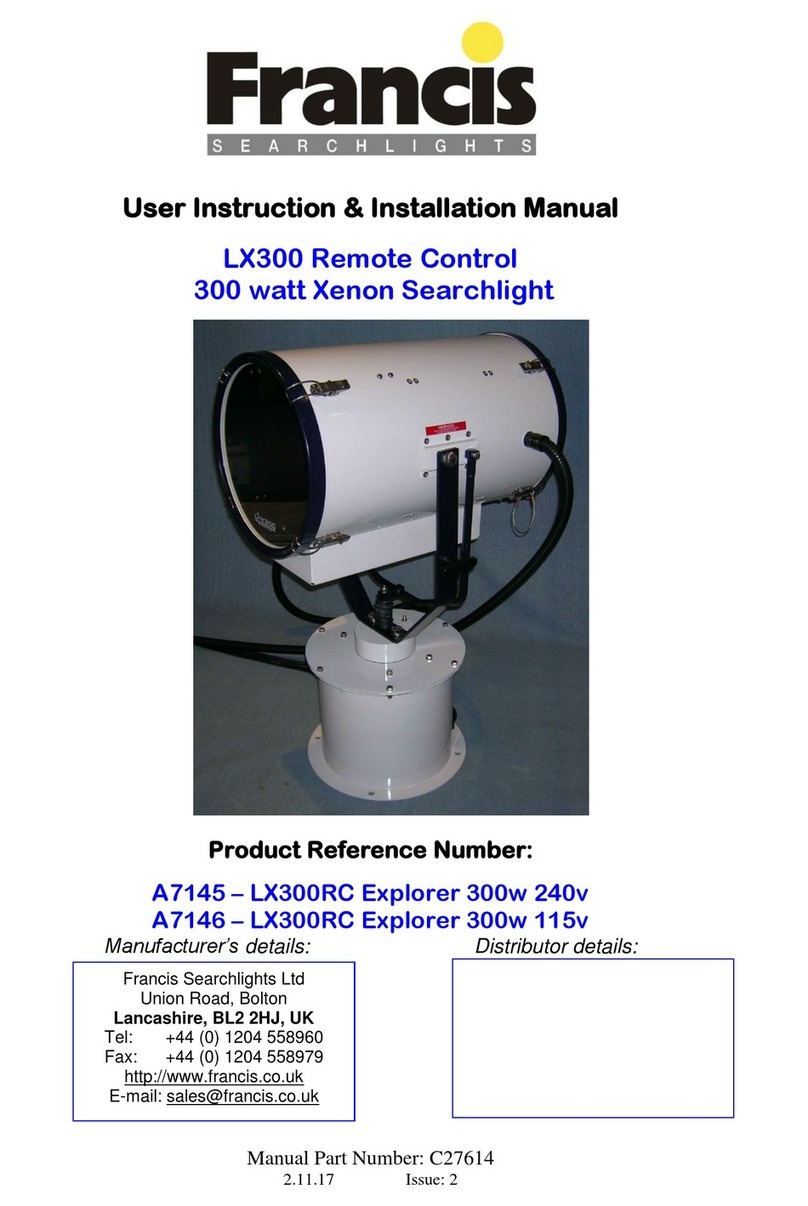
Francis Searchlights A7145 User instruction & installation manual

Francis Searchlights

Francis Searchlights A7145 User instruction & installation manual

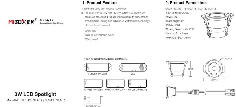
Miboxer SL1-12 quick start guide

Miboxer

Miboxer SL1-12 quick start guide

Mr. Beams MB370 installation instructions

Mr. Beams

Mr. Beams MB370 installation instructions

Sagitter Tracer user manual

Sagitter

Sagitter Tracer user manual

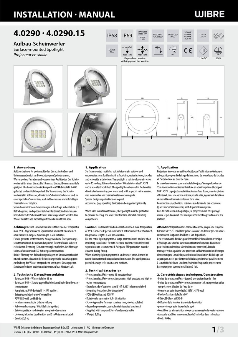
Wibre 4.0290 installation manual

Wibre

Wibre 4.0290 installation manual

Martin Mania SCX600 user manual

Martin

Martin Mania SCX600 user manual

Good Earth Lighting G19920-WH-I instructions

Good Earth Lighting

Good Earth Lighting G19920-WH-I instructions

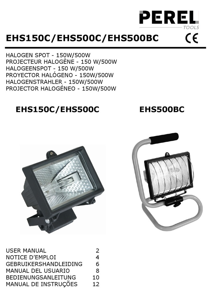
Perel EHS150C user manual

Perel

Perel EHS150C user manual

Honeywell Ex-Or MS1200PMBF Installation and commissioning instructions

Honeywell

Honeywell Ex-Or MS1200PMBF Installation and commissioning instructions

LEGRAND HPM Geo Spotlight Assembly and installation instructions

LEGRAND

LEGRAND HPM Geo Spotlight Assembly and installation instructions

Domus MURO-15S Series installation manual

Domus

Domus MURO-15S Series installation manual

manuals.online logo
manuals.online logoBrands
  • About & Mission
  • Contact us
  • Privacy Policy
  • Terms and Conditions

Copyright 2025 Manuals.Online. All Rights Reserved.