Wibre 4.0290 User manual

INSTALLATION · MANUAL
4.0290 · 4.0290.15
Aufbau-Scheinwerfer
Surface-mounted Spotlight
Projecteur en saillie
1. Anwendung
Aufbauscheinwerfer geeignet für den Einsatz im Außen- und
Unterwasserbereich zur Beleuchtung von Springbrunnen,
Wasserspielen, Fassaden und wassernahen Architektur. Der Schein-
werfer ist für einen Einsatz bis 15m max. Eintauchbemessungstiefe
geeignet. Die Konstruktion ist komplett aus V4A-Edelstahl 1.4571
gefertigt und zusätzlich epoliert. DieVerwendung des Schein-
werfers ist in Süßwasser, chloriertem Schwimmbadwasser und, in
einer speziellen Soleversion, auch in Meerwasser und solehaltiges
Thermalwasser möglich.
Sonderkonstruktionen-/anwendungen auf Anfrage. Zubehörteile (z.B.
Betriebsgeräte) sind optional lieferbar. Bei Einsatz im Unterwasser-
bereich muss der Scheinwerfer vor Einfrieren geschützt werden. Das
Wasser muss frei von metallangreifenden Bestandteilen sein.
Achtung! Betrieb Unterwasser und Luft bis zu einerTemperatur
max. 35°C. Angeschlossene Spezialkabel sind nicht zu entfernen
oder zu kürzen, längere Kabellängen >5 m lieferbar.
Für die gesamte lichttechnische Anlage wird eine Überspannungs-
schutzeinheit und dieVerwendung eines Trenntrafos zur sicheren
elektrischenTrennung (Schutztrennung) empfohlen. Bei Montage
sollte auf ausreichend ESD-Schutz geachtet werden.
Bei der Planung von Beleuchtungsanlagen im Unterwasserbereich
ist zu beachten, dass sich die Beleuchtungsstärke in Abhängigkeit
zurTrübung des Wasser entsprechend verringert. Die angegeben
Scheinwerferdaten beziehen sich immer auf das Medium Luft.
2. Technische Daten/Konstruktion
· Schutzart IP68 – Wassertiefe bis 15 m
· Schutzart IP69 – Schutz gegen Hochdruck und hohe Strahlwasser-
temperaturen
· Komplett ausV4A-Edelstahl 1.4571 epoliert
· Befestigungsbügel um 90° verstellbar
· POW-LED weiß und RGB-W
· rotationsymmetrische Lichtverteilung
· Kabelverschraubungs, V4A-Edelstahl epoliert
· Betriebsgeräte je nachVersion integriert oder extern
· Lieferung inklusive Leuchtmittel und 5 m Unterwasserkabel
· Gewicht 3,0 kg
1. Application
Surface mounted spotlights suitable for use in outdoor and
underwater areas for illuminating fountains, water features, facades
and waterside architecture.The spotlight is suitable for use in water
up to 15 m deep. It is made entirely ofV4A stainless steel 1.4571
and is also electropolished.The spotlight can be used in fresh water,
chlorinated swimming pool water and, with a special saline version,
also in seawater and thermal water containing sole.
Special designs/applications on request.
Accessories (e.g. operating devices) can be supplied optionally.
When used in underwater areas, the spotlight must be protected
to prevent freezing.The water must be free of metal-corroding
components.
Caution! Underwater and air operation up to a max. temperature
of 35°C. Connected special cables must not be removed or shortened,
longer cable lengths >5 m are available.
For the entire lighting system, a surge protection unit and use of an
insulating transformer for safe electrical disconnection (electrical
separation) are recommended. Adequate ESD protection must be
ensured during fitting.
When planning lighting systems in underwater areas, it must be
noted that water turbidity reduces illuminance.The spotlight data
provided always refer to air as the medium.
2. Technical data/design
· Protection class IP68 – up to 15 m water depth
· Protection class IP69 - protection against high pressure and high jet
water temperatures
· Entirely made of stainless steel 316Ti 1.4571 electro polished
· Mounting foot adjustable through 90°
· POW-LED white and RGB-W
· Rotationally symmetric light distribution
· Screw-type cable fastener, stainless steel, electro polished
· depending on version, control units integrated or external
· Supplied with lamp and 5 m of underwater cable
-Weight: 3,0 kg
1. Application
Projecteur à monter en saillie adapté pour l‘utilisation extérieure et
subaquatique pour l‘éclairage de fontaines, de jeux d‘eau, de façades
et l‘architecture au bord de l‘eau.
Le projecteur convient pour une installation jusqu‘à une profondeur de
15m. Construction entièrement réalisée en acier inoxydable électropoli
V4A 1.4571. Le projecteur est utilisable dans l‘eau douce, dans les piscines
chlorées et, dans une version spéciale pour la salée, également dans l‘eau
de mer et l‘eau thermale contenant de la salée.
Constructions/applications spéciales sur demande. Les accessoires
(p. ex. blocs d‘alimentation) sont disponibles en option.
Lors de l‘utilisation subaquatique, le projecteur doit être protégé
contre le gel. l‘eau doit être exempte d‘éléments agressifs contre les
métaux.
Attention! Opération sous-marine et aérienne jusqu‘à une tempéra-
ture max. de 35 °C. Les câbles spiralés raccordés ne doivent pas être retirés
ou raccourcis, longueurs de câbles > 5 m disponibles.
Il est recommandé d‘utiliser, pour l‘ensemble de l‘installation technique
d‘éclairage, une unité de surtension et un transformateur d‘isolement
pour l‘isolation électrique sûre (isolation de protection). Lors du
montage, veiller à garantir une protection suffisante contre les décharges
électrostatiques.Lors de la planification d‘installation d‘éclairage sub-
aquatiques, noter que l‘intensité d‘éclairage diminue parallèlement
à la turbidité de l‘eau. Les données indiquées pour le projecteur se
basent toujours sur une installation à l‘air.
2. Caractéristiques techniques/Construction
· Indice de protection IP68 – jusqu‘à une profondeur de 15 m
· Indice de protection IP69 - protection contre la haute pression et les
températures élevées de l‘eau de jet
· Complet en acier inoxydable 316Ti 1.4571 epol
· Pied de fixation réglable à 90°
· POW-LED blanc et RVB-B
· Diffusion de la lumière à symétrie de rotation
· presse-étoupe acier inoxydable, epol
· Contrôlleur ou alimentation intégré ou externe selon la version externe
· Ampoule et câbles immergeables de 5 m inclus dans la livraison
· Poids: 3,0 kg
WIBRE Elektrogeräte Edmund Breuninger GmbH & Co. KG · Liebigstrasse 9 · 74211 Leingarten/Germany
239
226 71
180 226
90°
151
IP68 IP69
STAINLESS
STEEL V4A
1.4571
316Ti
ELECTRO
POLISHED POW-LED
INCL.
3.000 K
4.500 K
6.000 K
RGB-W
12 V-DC
230 V
90°
CABLE
INCL.
max 15m max 15m
4.0290
Bohrschablone Standfuß U-Bügel · Boring template U-bracket foot · Gabarit de perçage de Pied
12V-DC 230VDepends on version
Abhängig von der Version

INSTALLATION · MANUAL
3. Installation/Montage
Zur Installation sind die nationalen Sicherheitsvorschriften zu
beachten. Es wird keine Haftung für unsachgemäßen Einsatz oder
Montage übernommen. Bei nachträglichen Änderungen an den
Leuchten wird keine Haftung übernommen.
POW-LED Leuchten müssen immer in Reihenschaltung an entspre-
chenden Konstantstromnetzteilen (siehe Betriebsgeräte) betrieben
werden.
Die Leuchtengehäuse sind nicht zu demontieren, da zum Schutz die
Kabel vergossen sind.
Montage des Scheinwerfers ist im Aussen- und Unterwasserbereich
auf verschiedenstem Montagegrund möglich. Aufbaumonatge direkt
auf z.B. Beton, Pflaster, Platten, Holzdielen undWänden möglich.
Bei Montage inErdreich, Kies, Rasenflächen oder Beete ist ein
Fundament o.Ä. notwendig.
Da bei Projekten die Aufbausituationen variieren ist keine allgemein
gültige Montageanleitung möglich. Die Piktogramme verdeutlichen
typische Montagebeispiele.
3.1. Aufbaumontage des Scheinwerfers auf festem Untergrund
3.2. Aufbaumontage des Scheinwerfers inVerbindung mit Funda-
ment in losem Untergrund.
Montage
Bei Aufbaumontage des Scheinwerfers auf festem Untergrund wie
z.B. Beton, Steinplatten, Holz, Fassade oder Fundament 2 Befesti-
gungsbohrungen (Abstand 160mm) für M6 oder M8 anzeichnen
oder die Bohrschablone aus Manual anlegen. Am Objekt ausrichten
und 2 Bohrungen für M6 oder M8 Schrauben zur Befestigung des
Scheinwerfers vorsehen. Die Besfestigungsschrauben müssen aus
V4A Edelstahl sein. 3.3
Seitliche Schrauben M8 TX45 am Schweinwerfer etwas lösen, ggf.
Innensechskantschraube etwas lösen 3.4, den Schweinwerfer hori-
zontal (90°) stellen und den Bügel am Untergrund befestigen. 3.5
Nun den Schweinwerfer am Objekt ausrichten und Neigungswinkel
in 15° Schritten einstellen, Innensechskantschraube gegenVerdrehen
des Scheinwerfers anziehen (1,5Nm) und seitliche Schraube M8
TX45 ebenfalls anziehen (max 14Nm). 3.4
Hinweis: Der Scheinwerfer kann auch in beliebigen Neigungs-
winkel (<15° Schritte) ohneVerwendung der Innensechskantschraube
eingestellt werden, jedoch ist dies für hohe Druckbelastungen gegen
das Scheinwerfergehäuse (z.B. Fontaine) nicht zu empfehlen, da ein
Verdrehen des Scheinwerfers möglich ist. 3.4
Achtung: Nur werkseitig angeschlossenes Kabel verwenden.
Gewünschte Kabellänge bei Bestellung angeben.
ZurVermeidung von Gefährdungen darf die beschädigte äußere
flexible Leitung dieser Leuchte ausschließlich vom Hersteller, seinem
Servicevertreter oder einer vergleichbaren Fachkraft ausgetauscht
werden. Bei erhöhter mechanischer Beanspruchung sollte das Kabel
zusätzlich in einem Schutzrohr zur Leuchte verlegt werden.
Einzelanschlussader entsprechend den Vorschriften an den Netz-
teilen elektrisch anschließen. 3.6, 3.7, 3.8
3. Installation/mounting
The national safety regulations are to be observed during instal-
lation. No liability shall be assumed for any improper use or assem-
bly. No liability shall be assumed for any subsequent modifications
to the luminaires.
POW-LED luminaires must always be operated in series connection
at the relevant constant current power supply units (see operating
devices).
The luminaire housings should not be disassembled since the cables
are encapsulated to provide protection.
The spotlight can be installed both in outdoor and underwater areas
on a wide variety of installation base materials. Surface mounting
can be effected directly on concrete, pavement, slabs, timber floor-
boards and walls, for example. Foundations or the like are required
for installation in soil, grit, lawns or beds.
No generally applicable mounting instructions can be provided
since mounting situation differ from one project to the other. The
pictograms demonstrate typical installation examples.
3.1. Surface mounting of the spotlight on solid ground
3.2. Surface mounting of the spotlight in connection with a
foundation in loose ground.
Installation
When the spotlight is surface mounted on solid ground such as for
instance concrete, stone slabs, wood, faces or a foundation, mark
2 fixing holes (distance 160 mm) for M6 or M8 or use the drilling
template provided in the Manual. Align to the object and provide
2 boreholes for M6 or M8 screws to fasten the spotlight.The fasten-
ing screws must be made ofV4A stainless steel. 3.3
Slightly loosen the M8TX45 screws on the side of the spotlight, if
necessary loosen the hexagon socket screw 3.4 slightly, position
the spotlight horizontally (90°) and fasten the bracket to the ground.
3.5
After this, align the spotlight to the object and adjust the angle of
inclination in 15° steps, tighten the hexagon socket screw to prevent
the spotlight from twisting (1.5 Nm) and also tighten the side screw
M8TX45 (max. 14 Nm). 3.4
Please note: The spotlight can also be adjusted to any angle of
inclination (<15° steps) without using the hexagon socket screw,
however, this is not recommended for high-pressure loads against
the spotlight housing (e.g. fountain) as twisting of the spotlight is
possible. 3.4
Attention: Only use the cable connected at delivery. Please
specify desired cable length when ordering.
To avoid hazards, a damaged external flexible line of this luminaire
may only be replaced by the manufacturer, their service represen-
tative or a comparable specialist. In case of increased mechanical
strain, the cable should additionally be laid in a protective tube to
the luminaire.
Establish the electrical connection to the power supply units in
accordance with the regulations. 3.6, 3.7, 3.8
3. Installation/Montage
Les règles de sécurité nationales doivent être respectées au moment
de l’installation. Aucune responsabilité n‘est acceptée en cas
d‘utilisation ou d‘installation incorrecte. Aucune responsabilité n‘est
prise en cas de modifications ultérieures des luminaires.
Les luminaires POW-LED doivent toujours être connectés en série
avec des unités d‘alimentation en courant constant appropriées
(voir équipement de commande).
Les boîtiers des luminaires ne doivent pas être démontés car les
câbles y sont scellés pour les protéger.
Le montage du projecteur est possible à l‘extérieur et sous l‘eau
sur une grande variété de surfaces de montage. Il est possible
d‘effectuer un montage en surface directement sur, par exemple, du
béton, des pavés, des dalles, des planches en bois ou des murs. En
cas d’installation dans la terre, dans du gravier, des pelouses ou des
parterres de fleurs, une fondation ou similaire est nécessaire.
Étant donné que les situations d‘installation varient d‘un projet à
l‘autre, il n‘existe pas d‘instructions d‘installation valables en général.
Les pictogrammes illustrent des exemples d‘installations typiques.
3.1 Montage extérieur du projecteur sur une surface solide
3.2 Montage extérieur du projecteur avec une fondation dans un
sol meuble.
Montage
Pour le montage extérieur du projecteur sur une surface solide
telle que du béton, des dalles de pierre, du bois, une façade ou une
fondation, marquez 2 trous de montage (distance 160 mm) pour M6
ou M8 ou utilisez le gabarit de perçage du manuel. Alignez sur l‘objet
et prévoyez 2 trous pour des vis M6 ou M8 pour fixer le projecteur.
Les vis de fixation doivent être en acier inoxydableV4A. 3.3
Desserrer légèrement les vis latérales M8TX45 du projecteur, si
nécessaire, desserrer légèrement la vis à six pans creux 3.4, placer le
projecteur à l‘horizontale (90°) et fixer le support à la base. 3.5
Ensuite, aligner le projecteur sur la cible et régler l‘angle
d‘inclinaison par étapes de 15°, serrer la vis à six pans creux pour
empêcher le projecteur de tourner (1,5Nm) et serrer également la vis
latérale M8TX45 (max 14 Nm). 3.4
Remarque: le projecteur peut également être réglé à n‘importe
quel angle d‘inclinaison (par étapes de <15°) sans utiliser la vis à
tête cylindrique, mais cela n‘est pas recommandé en cas de charges
de pression élevées contre le boîtier du projecteur (une fontaine par
exemple), car une torsion du projecteur est possible. 3.4
Attention: n‘utilisez que des câbles installés en usine. Précisez la
longueur de câble souhaitée lors de la commande.
Pour éviter tout danger, le câble flexible extérieur endommagé du
luminaire ne doit être remplacé que par le fabricant, son représen-
tant de service ou un spécialiste comparable. En cas de contrainte
mécanique accrue, le câble doit en outre être passé dans une gaine
de protection jusqu‘au luminaire.
Branchez les fils électriques de connexion individuels aux unités
d‘alimentation conformément aux réglementations.
3.6, 3.7, 3.8
2/3 WIBRE Elektrogeräte Edmund Breuninger GmbH & Co. KG · Liebigstrasse 9 · 74211 Leingarten/Germany
75°
90°
0°
60°
45°
90°
30° 15°
70
min 0,5m
Object
90
M6
M8
160
Fixing
screw
M8 TX45
max 14Nm
1,5Nm
HEX
screw
2mm
75°
90°
0°
60°
45°
90°
30° 15°
3.1 3.2
3.3
3.5
3.4

INSTALLATION · MANUAL
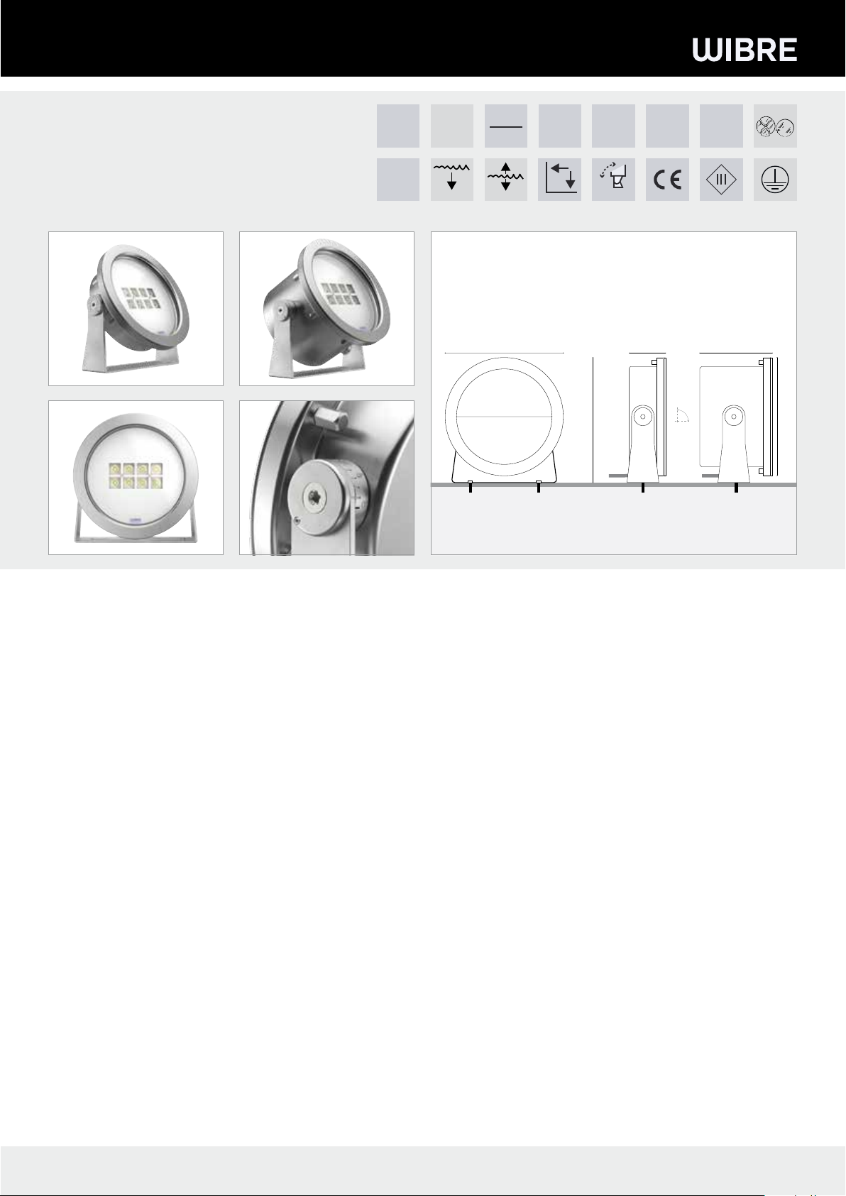
Installing the spotlight
Re-align all spotlights to the object, readjust if necessary,
check the angle of inclination and tighten the fastening screw
M8TX45 (max. 14 Nm).
4. General service information
-When cleaning, make sure that the lights do not come into contact
with metal-corroding cleaning agents.The use of cleaning agents
containing hydrochloric acid on and near spotlight parts made of
stainless steel must always be avoided.
- Clean spotlights and installation housing regularly to avoid
extraneous rust deposits.
-The effect of a high-pressure jet between the glass and the cover
may cause the paper seal (AFM) to roughen.This has no effect on
the function and tightness of the projector and does not constitute
a warranty claim!
- Attention: Protect lightbulbs from freezing; they must be
removed,
if necessary, or specially protected.
- Lost screws may only be replaced by screws made ofV4A.
- Depending on load (wattage, external conditions), we recommend
changing the seals (on the glass pane, screws, O-ring) and cable
every 5–8 years.
Please note: Do not use as a climbing aid! Avoid pressure loads
on the installed spotlight.The U-bolt is designed to withstand the
load of water.
6. Warranty conditions
Our warranty conditions can be found on the respective warranty
card for the product and at wibre.de/warranty.
WIBRE Elektrogeräte Edmund Breuninger GmbH & Co. KG · Liebigstrasse 9 · 74211 Leingarten/Germany
3.8
Montage des Scheinwerfers
Alle Scheinwerfer erneut zum Objekt ausrichten, ggf. nachjustieren,
Neigungswinkel kontrollieren und Befestigungsschraube M8TX45
festziehen (max 14Nm).
4. Allgemeine Wartungshinweise
- Beim Reinigen darf die Leuchte nicht mit Metall angreifenden
Reinigungsmitteln in Berührung kommen. Der Einsatz salzsäure-
haltiger Reinigungsmittel an und in der Nähe von Scheinwerfer-
teilen aus Edelstahl ist in jedem Fall zu unterlassen.
- Scheinwerfer und Einbaugehäuse regelmäßig reinigen,
um Fremdrostablagerungen zu vermeiden.
- Durch die Einwirkung eines Hochdruckstrahls zwischen Glas und
Blende kann ein Aufrauen der Papierdichtung (AFM) entstehen.
Dies hat keine Auswirkungen auf die Funktion und Dichtigkeit des
Scheinwerfers und stellt keinen Garantiefall dar!
- Achtung: Strahler vor Einfrieren schützen, gegebenenfalls
müssen diese demontiert oder speziell geschützt werden.
-Verloren gegangene Schrauben dürfen nur durch Schrauben aus
V4A ersetzt werden.
- Je nach Beanspruchung (Höhe der Watttage, äußere Umstände) ist
alle 5–8 Jahre einWechsel der Dichtungen (Glasscheibe,Verschrau-
bung, O-Ring) und der Kabel zu empfehlen.
Hinweis: Nicht als Steighilfe verwenden! Druckbelastung auf
montiertem Scheinwerfer vermeiden. Der U-Bügel ist dafür ausge-
legt, die Belastung durchWasser stand zuhalten.
6. Garantiebestimmungen
Unsere Garantiebedingungen finden Sie auf der jeweiligen
Garantiekarte des Produkts und unter wibre.de/warranty.
max 40 m
rot/red
schwarz/black
5.0630.10.08 SELV
4.0290.00 MONO
prim
230 V
50-60 Hz
sec
max 1
4.0290.15 MONO
integrated
power supply
N L GND
PRIM
230V
50-60Hz
max 40 m
5.0670.19.52
5.0635.19.52
4.0290.00 + 4.0290.15 RGB-W
sec
NTC CH1 2 3 4
DMX
OUT
DMX
IN
prim
230 V
50-60 Hz
max 1
SELV
3.6 3.73.8
7. Wichtige Hinweise (Bei Nichtbeachtung folgender
Punkte, entfällt die Garantie.)
• Vor der Installation müssen alle Teile auf Transportschäden überprüft werden!
• Jegliche Montage-, Installations- und Elektroarbeiten müssen von qualifi-
ziertem Fachpersonal durchgeführt werden.
• ZurVermeidung von Gefährdungen darf eine beschädigte äußere flexible
Leitung dieser Leuchte ausschließlich vom Hersteller, seinem Servicevertreter
oder einer vergleichbaren Fachkraft ausgetauscht werden.
• Die Lichtquelle dieser Leuchte darf nur vom Hersteller oder einem von ihm
beauftragten Servicetechniker oder einer vergleichbar qualifizierten Person
ersetzt werden.
• ZurVermeidung von Fremdrost nur Edelstahlwerkzeug verwenden!
• Die Kabellänge der Leuchten ist so zu wählen, dass man nicht im Wasser oder
feuchten Umgebung verlängern muss. Spätere Reklamationen aufgrund
dessen können nicht akzeptiert werden.
• Es dürfen nur originale Wibre-Betriebsgeräte verwendet werden.
• Ein Montageabstand von 10 cm zwischen Betriebsgeräten wird dringend
empfohlen, um wechselseitiges Erhitzen zu vermeiden.
• Anschluss der Betriebsgeräte muss stromlos erfolgen, da sonst Entladungen
im Netzteil zur Schädigung der LED führen können.
Es darf keine Primärspannung beim Wechsel der LED anliegen.
• Beim Anschließen der Leuchte die Polung beachten! Eine falsche Polung kann
dem LED-Modul schaden.
• Die Installation eines bauseitigen Überspannungsschutzes nach
DIN VDE 0100-443, DINVDE 0100-534 und EN 62305 wird empfohlen.
• Bitte achten Sie auf Maßnahmen gegen ESD (Elektrostatische Entladung)
während aller Arbeiten am Scheinwerfer, Betriebsgerät und LED.
7. Important information (If the following points
are disregarded, the guarantee expires.)
• Before installation, all parts must be checked for transport damage!
• All fitting, installation and electrical work must be performed by qualified
specialist staff.
• To avoid any hazards, a damaged external flexible cable of this luminaire
should only be replaced by the manufacturer, his service representative or a
comparable specialist.
• The light source of this luminaire may only be replaced by the manufacturer
or a service technician appointed by him or a comparably qualified person.
• Only use stainless steel tools to avoid external rust!
• The cable length of the lights should be chosen in such a way that it is not
necessary to extend in water or moist environments. Later complaints
resulting from this cannot be accepted.
• Only original Wibre operating units may be used.
• An installation distance of 10 cm between operating devices is urgently
recommended in order to avoid mutual heating up.
• The operating devices must be connected without power, as otherwise
discharges in the power supply may cause the LED to be damaged. No
primary voltage may be applied when changing the LED.
• Note polarity when changing the lights!The wrong polarity can damage the
LED module.
• It is recommended that the customer install an overvoltage protection in
accordance with DINVDE 0100-443, DIN VDE 0100-534 and EN 62305.
• Please comply with all anti-ESD (electrostatic discharge) measures during all
work on the spotlight, operating device and LED.
7. Remarques importantes (La garantie s‘éteint en
cas de non-respect des points suivants)
• L‘absence d‘avaries de transport doit être vérifiée avant l‘installation !
• Tous les travaux de montage et d‘installation, ainsi que les travaux élec-
triques, doivent être réalisés par du personnel qualifié.
• Pour éviter tout danger, un câble flexible externe endommagé du projecteur
ne peut être remplacé que par le fabricant, son représentant de service ou un
spécialiste qualifié.
• La source lumineuse de ce liminaire ne peut être remplacée que par le
fabricant ou un technicien de service désigné par lui ou par une personne
ayant une qualification comparable.
• Afin d‘éviter tout dépôt de rouille, utiliser exclusivement des outils en acier
inoxydable !
• La longueur de câble des lampes doit être choisie de telle sorte à ce qu‘il ne
soit pas nécessaire de la prolonger dans de l‘eau ou dans un environnement
humide.Toute réclamation ultérieure à ce motif ne sera pas acceptée.
• Seuls des équipements Wibre originaux doivent être utilisés.
• Une distance de montage de 10 cm entre les équipements est vivement
recommandée afin d‘éviter un réchauffement mutuel.
• Le raccordement des équipements doit être effectué sans courant, sans
quoi des décharges dans le bloc d‘alimentation pourraient entraîner une
détérioration des LED. Aucune tension primaire ne doit être établie lors du
changement des LED.
• Lors du raccordement des lampes, respecter la polarité ! Une erreur de
polarité peut endommager le module de LED.
• L‘installation d‘une protection contre la surtension par le client conforme aux
normes DIN VDE 0100-443, DINVDE 0100-534 et EN 62305 est recommandée.
• Veuillez respecter les mesures contre la décharge électrostatique durant tous
les travaux sur des projecteurs, équipements et LED.
Montage du projecteur
Alignez à nouveau tous les projecteurs sur leur cible, réajustez si
nécessaire, vérifiez l‘angle d‘inclinaison et serrez la vis de fixation
M8TX45 (max 14 Nm)
4. Instructions d‘entretien générales
- Lors du nettoyage, le projecteur ne doit pas entrer en contact
avec des détergents agressifs contre les métaux. L‘utilisation de
détergent à base d‘acide chlorhydrique sur et à proximité des pièces
du projecteur en acier inoxydable est totalement interdite.
- Nettoyer régulièrement le projecteur et le boîtier de montage afin
d‘éviter tout dépôt d‘oxydation.
- L‘effet d‘un jet à haute pression entre le verre et la collerette peut
provoquer la rugosité du joint en papier (AFM). Cela n‘a aucune
incidence sur le fonctionnement et l‘étanchéité du projecteur et ne
constitue pas un droit à la garantie!
- Attention: Protéger les projecteurs contre le gel ; le cas
échéant, les démonter ou assurer une protection spéciale.
- Les vis perdues ne doivent être remplacées que par des vis en acier
inoxydableV4A.
- Selon la sollicitation (puissance, circonstances environnementales), il
est recommandé de procéder au changement des joints (sur les vitres,
les raccords vissés et les joints toriques) et du câble tous les 5 à 8 ans.
Remarque : Ne pas utiliser comme aide à la montée ! Évitez
toute charge de pression sur le projecteur monté. L’étrier en U est
conçu uniquement pour résister à la charge de l‘eau.
6. Conditions de garantie
Nos conditions de garantie se trouvent sur la carte de garantie
correspondante du produit et sous wibre.de/warranty.

W1006 Stand 06.21 - Technische Änderungen vorbehalten - Für Druckfehler übernehmen wir keine Haftung
4.0290
Bohrschablone Standfuß U-Bügel · Boring template U-bracket foot · Gabarit de perçage de Pied
70 mm
226 mm
90 mm
10 mm
60 mm
10 mm
10 mm
This manual suits for next models
1
Other Wibre Spotlight manuals
Popular Spotlight manuals by other brands

Strong International
Strong International RADIANCE 72-00800 instruction manual

Kenroy Home
Kenroy Home 20506 Use and care guide

LUMIT
LUMIT 111980901 instruction manual

HAMPTON BAY
HAMPTON BAY 0045-0BZ-01FJ Use and care guide

Astral Pool
Astral Pool LUMIPLUS FLEXIMINI MONOCOLOR-RGB DMX instruction manual

North Light
North Light MF-3072 instruction manual

HQ Power
HQ Power VDL10MB quick start guide

IMG STAGE LINE
IMG STAGE LINE PARL-40DMX instruction manual

Arena Luci
Arena Luci SOUL LED 8 user manual

LIVARNO LUX
LIVARNO LUX LSS 520 A1 User manual and service information

HQ Power
HQ Power VDPLS1025 user manual

Show Tec
Show Tec Phantom 250 CMY Wash V2 instruction manual