iM3 P4 User manual
1
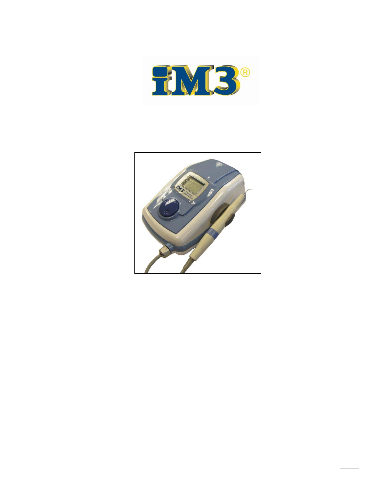
Model P4 Ultrasonic Scaler
Owners Manual
Version: May 2008
User Manual iM3 P4
Piezoelectric Ultrasonic Scaler
iM3 Pty Ltd. iM3, Inc.
Unit 9/31-33 Chaplin Drive 12119 NE 99th Street, Suite 2060
Lane Cove NSW 2066 Vancouver, Washington, USA
Tel: + 61 2 9420 5766 Tel: + 1 800 664 6348
Fax: + 61 2 9420 5677 Fax: + 1 360 254 2940

2
Web: www.im3vet.com Web: www.im3vet.com
Contents
Operator Safety………………………………………………………………….. 3
Warnings……………………………………………………………………………… 4
Notes before using…….………………………………………………………. 5
Preface ………………………………………………………………………………. 6
Contents ……………………………………………………………………………..
I. Descriptions and Functionalities of Components …………… 7
II. Installation Guide …………………………………………………………. 10
III. Preparation and Practice before the First Use …………… 11
IV. Operation Procedures …………………………………………………… 13
V. Maintenance ………………………………………………………………….. 14
VI. Cleaning and Sterilization ……………………………………………. 15
VII. Specifications ……………………………………………………………... 16

3
Operator Safety
Read this page carefully before installation and use.
The instrument described in this manual is designed to be used by properly trained
personnel only. Only qualified personnel shall carry out adjustment, maintenance and repair
of the equipment.
NOTE, CAUTION AND WARNING STATEMENTS
NOTE: Indicates some operating tips.
CAUTION: Indicates correct operating or maintenance procedures in order to prevent
damage to or destruction of the equipment or other property.
WARNING: Calls attention to a potential danger that requires correct procedures or
practices in order to prevent personal injury.
SYMBOLS
“BF” symbol indicates the ART-P4 was manufactured
according to the degree of protection against electric shock
for this type BF equipment.
Grounding Terminal
Attention, Reading the instructions
!

4
Warnings
Important Notes!
The equipment is only to be used by a qualified doctor, dentist, hygienist or other qualified
personnel.
A patient with pacemaker cannot be treated with the equipment.
A shielded AC power cord must be used with this equipment.
iM3 -P4 should be powered from a separate wall outlet with grounding point.
Attention!
Avoid use of this machine around Pacemakers.
It has been shown that electronic appliances including razors, hair dryers, microwave ovens,
TV receptors, and some electronic medical equipment may interfere with the normal
operations of pacemakers. It is suggested that patients who have pacemakers avoid
treatment with this Scaler. For further readings on the subject, please refer to:
"Advances in Cardiac Pacemaker", The New York Academy of Sciences, Vol. 167,
Article 2, pp. 515-1075
"Electromagnetic Radiation Interference with Cardiac Pacemaker", U. S. Department
of Health, Education and Welfare
"The Individual with a Pacemaker in the Dental Environment", Journal of the
American Dental Association, Vol. 91, No. 6, pp. 1224-1229
!

5
Notes before using:
The electric power used must be grounded. If this
requirement is not met, it could cause damage to the
Scaler and more importantly harm to the user.
The machine should be placed on a steady and stabled
platform or table. Placing the machine on an unstable,
tilted table may degrade the performance and/or may
accidentally cause damage to the system.
Do not dismantle the machine. Unauthorised/non
certified technicians may cause harm to themselves
and/or cause damage to the machine.
For electrical safety, the power cord should not be
placed under heavy objects, and should also be kept
away from high temperature heat sources.
If you observe any abnormal situations while the machine
is in use, unplug the power cord as a safety precaution.
iii

6
Preface
Piezo Scaler is developed based on the Principle of piezoelectric. Ultrasonic waves are generated in
the handpiece by 4 ceramic piezoelectric plates subjected to high frequency alternation current.
The Tip is vibrated back and forth in high speed to perform tooth calculus and/or tartar cleaning
task. Particularly, the high speed vibrated Tip can remove the toughest calculus and tartar easily,
and in conjunction with syringe (or saliva ejector), the scaler can conveniently and swiftly clean
teeth and most importantly it is proven to be electrically safe. The electric-mechanical efficiency
of this piezoelectric system is much greater than that of traditional magnetostrictive systems. There
is very little heat released, and it is possible to work with very little spray. It’s sufficient to ensure
excellent cavitations but more comfortable for both the patient and the dental surgeon.
The unit is a very powerful apparatus. There are linear scales of power adjustment for removing
prostheses. This allows very fine adjustment to suit each clinical situation.
With a large range of Tips, the unit is suitable with different kinds of works.
iM3 - P4
Operation Modes:
Perio, Scaling and Endo
Operation Frequency: 29 KHz
Stable and Fine Power Setting
Various Types of TIP Available
No Heat Generation of Handpiece
Special notes to operator:
Since the tip of scaler is made of stainless steel, avoid direct contact to patient's mouth; it may
cause damage to the enamel of the teeth. To better utilize all the functions and maximize the
performance of the scaler, it is suggested that before applying to patients, doctors should
practice on models/aluminum plates to familiarize themselves with the usage of the scaler tips,
the subtle motion force of the insert, etc.
iv
7
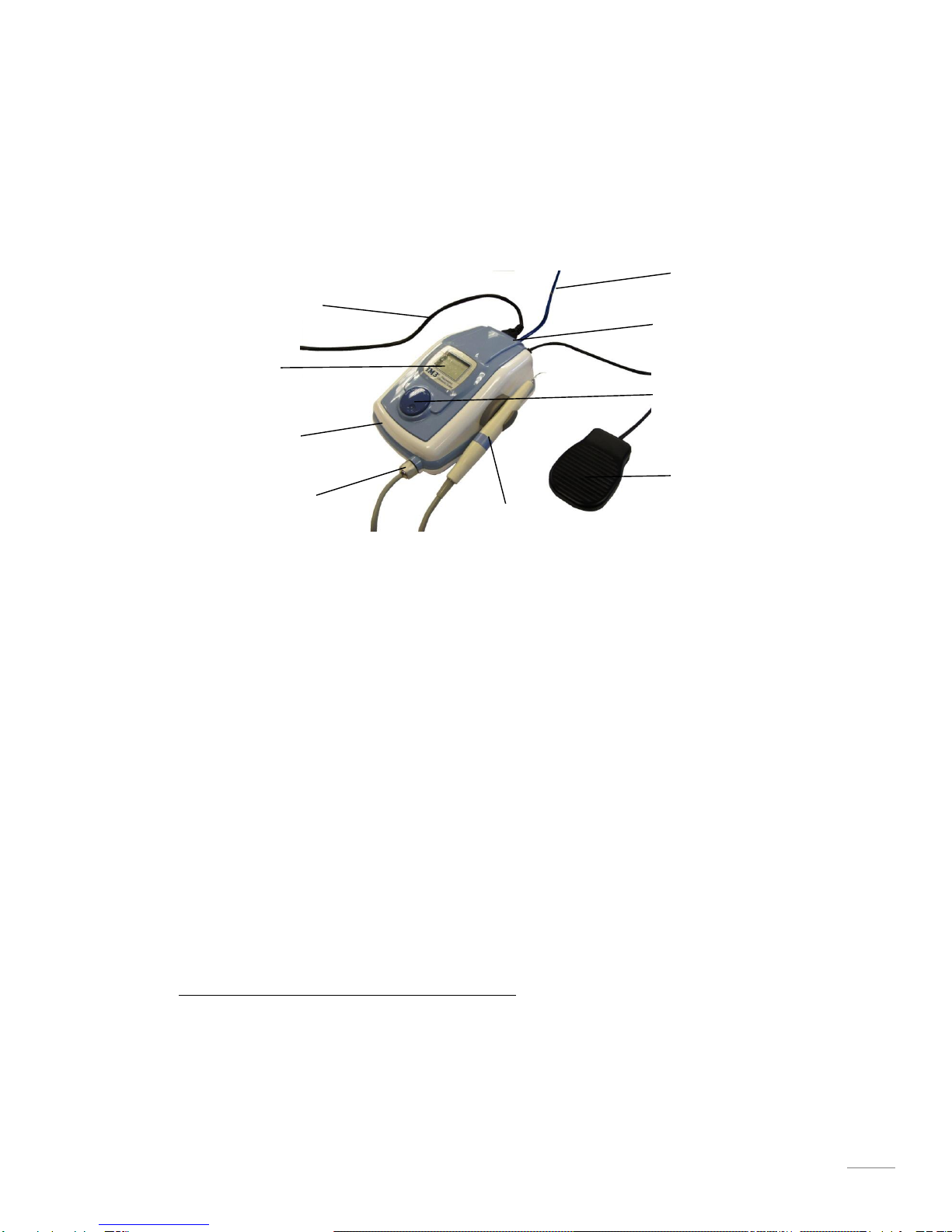
I. Descriptions and Functionalities of Components
1. Main Unit
It is the heart of the scaler. Functionally, the main unit generates the needed 29 KHz-
operation-signal and passes it onto the handpiece, and thus induces power to vibrate the
tip inside the handpiece accordingly. Due to loading variations, a signal from the handpiece
will be fed back to the main unit so that the main unit can track the variation of the loading
and adjust the intensity of the controlling signal accordingly.
2. Handpiece
The handpiece consists of vibrator and a tip. The vibrator is composed of four pieces of
piezoelectric plates. It will generate displacement when driven by the electrical signal from
the main unit. The vibrator will move the tip back and forth in high speed based on the
waveform change of the controlling signal. In addition, the movement of the Tip will induce
current on the feedback circuit and the induced signal is then fed back to the Main Unit to
complete the control loop. In accordance with the movement of the tip, a powerful
water stream (working like a syringe) will also come out to a) wash away the tooth calculus
and tartar, and b) cool down the temperature of the tip (heat generated from the vibration
of the tip).
Caution: Make sure that new tip is fully seated.
3. Footswitch
The convenient footswitch helps operators to easily turn on/off the scaler without
interrupting the cleaning process.
1
v
4
7
3
6
1
8
2
5
9

8
4. Power Cord
5. Water Tubing
Connect to pressurized water supply
6. LCD Panel
User can adjust the power level and operation mode clearly and easily by looking at the
LCD panel. The figure and scale show the current power level. The operation mode tells
user, which appropriate insert should be applied.
Caution: To prevent any damages, Tip operation has to be chosen according to the
operation mode shown on the LCD panel.
7. Main Power Switch
Main power switch. When pushed, the AC power is sent to the Main Unit, and the power
indicator (LED) will be lit up. If pushed again, the power is then turned off and the power
indicator will be extinguished.
Before turning the unit on, be sure the footswitch is in
the “OFF” position.
8. Water Flow Control
Turning this knob clockwise will decrease the volume of water flowing onto the tip, turning
counter-clockwise will increase the flow.
Important note: As well as washing away the debris left from the calculus and/or tartar,
the water acts to cool the handpiece and in particular the scaling tip. Ensure there is
adequate flow to minimize heat build-up.
Warning: Don’t adjust water knob in anti-clockwise direction over three circles
9. Power
Output power intensity control knob. When turned counter-clockwise, the output power
intensity will be smaller. On the other hand, when turned clockwise, the output power
intensity will increase. This power intensity control knob gives doctors the flexibility to
adjust the output power intensity based on the difficulty of the cleaning job (e.g.,
toughness of the calculus).
!

9
II. Installation Guide
1. Unpacking
When unpacking the box, check iM3 - P4 for any damage. If damaged, please contact your dealer
immediately. Enter the unit serial number on your warranty card mail it within 10 days after setting
up the machine.
2. Storage
A. Environment:
The unit should be stored in a clean, dry environment. The following environmental limitations
apply to both storage and shipping:
Temperature: 0℃to 60℃
Humidity : 10%~90% (at 40℃)
Atmospheric pressure: 860~1060 hPa
B. Labels
Explanations of the labels printed on the outside box are listed below:
FRAGILE
KEEP AWAY FROM WATER
DON’T HOOK
THIS SIDE UP
3. Safety Instructions
10
A. Grounding:
Before any connection to the output connectors is made, the unit must be grounded. The mains
plug should only be inserted into a wall socket provided with a protective earth contact.
Note: The unit must be positioned so that the plug is accessible.
B. Main voltage range and fuse:
Before inserting the main plug into the wall socket, make sure that the scaler is compatible with the
local main voltage.
Warning: The scaler should be disconnected from all voltage sources when a fuse is to be removed
or replaced.
The main (line) fuse holder is located on the rear panel in the main (line) input socket. When the
main (line) fuse needs replacing, proceed as follows:
Disconnect the unit from the line.
Remove the cover of the fuse-holder by means of a small screwdriver.
Fit a new fuse with the correct rating and refit the cover of the fuse-holder. The fuse
will be 2A/250V-delay action type.
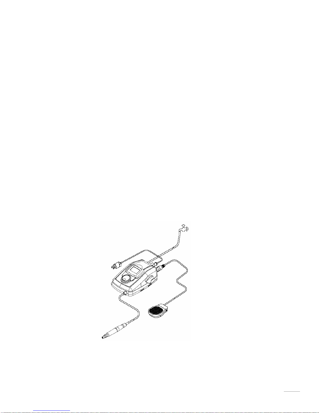
4. Setting Up
It is fairly simple to install the IM3 Scaler. Just unpack the IM3 Scaler box and connect the
components as shown in the figure below.
Figure 3. ART-P4 setting up diagram
1. Check the “ART-P4” and make sure the both power and power indicator is off when the
switch is off.
2. Put the Scaler into a grounded AC power outlet.
3. Choose the correct Tip for desired procedure, and insert it into the handpiece. Make sure

11
the insertion is complete.
4. Make sure the water PU tube is connected well.
Several installation suggestions are listed below:
1. Because patients may experience some tissue trauma during the treatment, it is suggested
that the operator use purified or distilled water. This will significantly reduce the possibility of
infection.
2. After installation, the extra length of the power cord should be neatly arranged to avoid any
tripping accidents.
3. The footswitch should be firmly placed in a position where the users can easily access it. Any
extra cord to the footswitch should also be neatly arranged to avoid any tripping accidents.
III. Preparation and Practice before the First Use
To better utilize all the functions and maximize the performance of the IM3 Scaler, it is suggested
that before treating patients, operators should practice on models/aluminum plates to familiarize
themselves with the system. Maneuver the head of the tip to gently touch the aluminum plate.
Try to familiarize and observe the subtleties of the force strengths under different tips, head angles,
positions, etc. Closely examine the scratches left on the aluminum plate after each practice, and
try to match each scratch to its originated head position and angle.
In addition, adjust the output power intensity by turning the power knob. Familiarize yourself
with the differences when changing the output power intensity. Finally, adjust the water volume
by turning the water volume control knob. Familiarize yourself and observe the subtleties among
different water volume situations. Observe the temperature of the handpiece when changing the
water volume. Do not overheat the handpiece. Perform the above practice procedures several
times to prepare yourself for operating on living subjects.
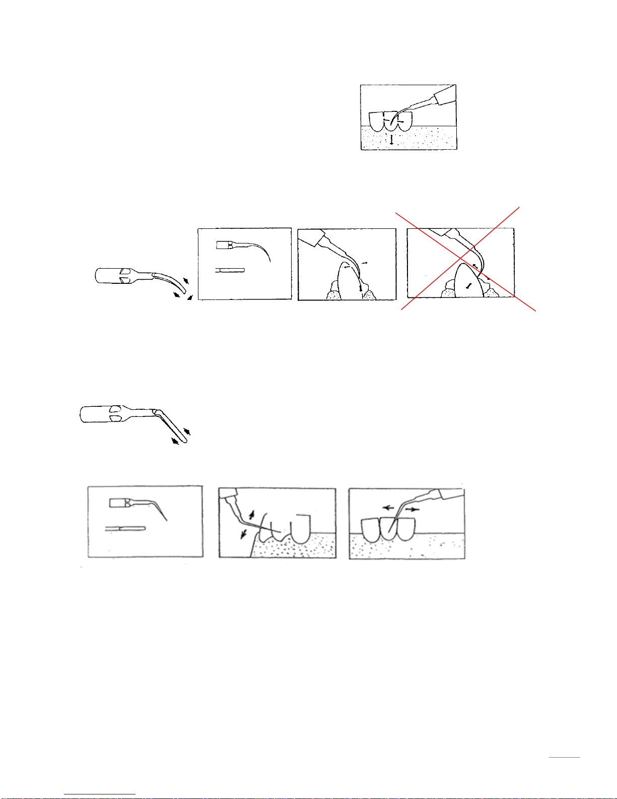
Below are some applications and ultrasonic movement of the Tip.
A. Tangential application (E5 TIP)
Apply light pressure on the sides of the tip while moving the handpiece slowly back and forth.
Do not apply the pointed end of the tip against the tooth, it will damage the enamel.
12
B. Frontal application (E2 TIP)
Using slight pressure, apply the flat end of the tip directly to
tartar buildup. The tip should be used in a chisel-like manner on the tartar with slight back and
forth movement.
Do not angle the tip so that the end is bearing down directly onto the tooth surface, damage to
the enamel will result.
Incorrect application
C. Tangential Application (E3 TIP)
Apply light pressure on the sides of the tip while moving the handpiece slowly back and forth.
Do not apply the pointed end of the tip against the tooth, it will damage the enamel.
IV. Operating Procedures
When preparing to treat a patient:
Step 1: Push the POWER SWITCH to light the ON indicator (LED).
Step 2: Check the water.
Step 3: Select the needed tip, make sure it is fully seated with the Handpiece.
Step 4: Set the POWER KNOB to the suitable level for the insert.
Step 5: Hold the Handpiece with the Tip end pointing up over a suitable drain.
Step on the foot control and allow water to run from the
Handpiece for a few seconds until it flows without spurting.

13
Caution: The above procedure should be repeated each time when a Tip is replaced into the
handpiece.
Caution: Make sure that the water spray is at the desired temperature and is reaching the
working edge of the tip.
Step 6: Place the tip into the patient’s mouth and use the foot control to
activate the handpiece and water flow.
V. Maintenance
The iM3 unit does not need a special maintenance routine but it does need to be regularly
and thoroughly cleaned and sterilized (as described in next section).
Daily start-up
When starting the unit at the beginning of the day:
Open the water supply shut-off valve.
Push the MAIN POWER SWITCH to light the on indicator (LED)
Note: If no water comes out, please check the water supply.
Note: If power LED does not light, please contact iM3.
Daily shut-off
When stopping the unit at the end of the day:
Push the POWER SWITCH to turn the unit off.
Turn off the water supply shut-off valve.
Preparing to treat a patient
Make sure the tip has been sterilized.
The following suggestions are also useful in extending the product life of the unit.
A. Place the main unit in an open area where air can flow freely around it.
B. If you need to move the main unit, handle with care.
C. Before leaving the operatory, make sure the AC power is turned off and the water tap is tightly
closed.
D. After six months or if you find the output power of the handpiece is not enough to perform
treatment, it is possible that the tip is worn out. If the tip is worn out, replace it with a new

14
one otherwise, have your authorized agent service the system.
E. Customer Service: if service is needed, please contact your authorized agent.
Trouble shooting
Product requiring any maintenance should be returned to the customer service department or
authorized service facility. iM3 will repair or replace any product under warranty at no charge.
VI. Cleaning and Sterilization
In this section we describe the procedures to clean and sterilize the scaler. It is important to
follow these procedures before using the machine otherwise, patients and/or operators may
risk the possibility of infection. Below we detail the infection control procedures for the
handpiece, the tip and the main unit respectively.
Handpiece
Before cleaning, remove the tip from the handpiece. Let the handpiece run for a couple of
seconds to drain out the water and any possible contamination left inside the handpiece. The
outer surface of the handpiece should be cleaned with an antiseptic soap or solution. Rinsed
off with water and wiped or sprayed with a chemical disinfectant that is compatible with the
handpiece material. A sterile insert or tip is then reassembled to the handpiece in preparation
for the next patient.
Warning: Do not put the handpiece and the extension wire directly into the sterilized fluid.
Any left such fluid inside the machine will interfere with the normal operations of
the system.
At the end of the day with the tip removed, the handpiece and cable should be scrubbed with
an antiseptic soap or solution and rinsed off with water. The handpiece should be scrubbed a
second time with an antiseptic soap or solution and rinsed off with water.
Warning: The chemical disinfectant should not be allowed to remain on the surface longer
than the recommended time or material damage may result.
Note: Cleaning of the Handpiece is recommended after each patient use.
Tip
After each use, there will be saliva and/or blood or other debris left on the tip, consequently, it
is necessary to clean the tip with a supersonic cleaner first. This can be done manually by
scrubbing with a brush or by use of an ultrasonic cleaner with a solution of detergent and
water. After scrubbing, the tip should be rinsed thoroughly with water to remove all detergent.
Then dry the rinsed tip and place the tip in a bag and then put it into a medical-equipment
autoclave and sterilize 260℉(127℃) for 30 minutes or as recommended by the manufacturer of
the particular sterilizer used.

15
Warning: High room temperature conditions, improper dilutions, or excessive immersion time
in a chemical sterilant can result in damage to the plastic and elastomeric
materials of the Tips.
Caution: The use of a dry heat oven, incompatible chemical vapor type sterilizers or
quaternary ammonium compounds must be avoided as damage can result to the
plastic and elastomeric materials.
Warning: Don’t try to change the shape of the tip, it may reduce the power output.
Note: Replace one new Tip if you find damage, worn or weak power of the Tip.
Main Unit
Since the Main Unit does not have direct contact with the patients, the cleaning is simple.
Just carefully swab the Main Unit with absolute alcohol calomel, and keep it away from dust.
(If other detergent is used, choose one that will have no chemical effects on the surface of the
plastic case of the Main Unit. If not sure, please test a small area first.)
VII. Specifications
The iM3 P4 scaler is designed and manufactured to meet the most demanding environment. It’s
specifications are listed below
Classifications
Type of protection against electric shock:Class II
Degree of protection against electric shock:Type BF
Degree of protection against the harmful ingress of water:IP40
Mode of operation:Continuous
According to medical device directive:IIa
Complies to following Directive/Standards
ISO13485 - Medical devices - Quality Management Systems–requirements
for regulatory purposes
93/42/EEC –MDD CE directive
EN60601-1: Medical Electrical Equipment, General Requirement for Safety
EN60601-1-2: Medical Electrical Equipment, Electromagnetic Compatibility
-Requirements and Tests
EN55011: Limits and methods of measurement of Radio Disturbance Characteristics of

16
Industrial, Scientific and Medical (ISM)
Radio- Frequency Equipment
Specification
Power supply
230V ±5% ~50/60Hz 0.16A 36.8VA
Working frequency
26KHz ~ 32KHz
Water supply
25~60 PSIG(172~414KPa)
Dimension
22.5cm(L) x 18cm(W) x 9.5cm(H)
Weight
2.5 Kg(include handpiece)
Handpiece Cable
250 cm
Footswitch Cable
250 cm
Operation environment
Temperature
0°C~60°C
Relative Humidity
10% ~ 90% (non-condensing)
Transport and storage conditions
Temperature
0°C~60°C
Relative Humidity
10% ~ 90% (non-condensing)
Atmospheric pressure
860~1060 hPa
Table of contents
Other iM3 Media Converter manuals


