iM3 ultra-S User manual
Instructions for Use
Piezoelectric Ultrasonic Scaler
U8200, U8300
ultra-S
|
ultra-ST

2
Contents
Symbols.......................................................................................................................................................................................................... 4
1. Introduction............................................................................................................................................................................................... 5
2. Electromagnetic compatibility (EMC)..................................................................................................................................................... 7
3. Unpacking .................................................................................................................................................................................................. 8
4. Scope of delivery ....................................................................................................................................................................................... 9
5. Safety notes ............................................................................................................................................................................................ 10
6. Description .............................................................................................................................................................................................. 13
Control unit U8200............................................................................................................................................................................. 13
Control unit U8300............................................................................................................................................................................. 14
LED Handpiece ................................................................................................................................................................................... 15
Foot Control U8007............................................................................................................................................................................ 16
7. Start-up .................................................................................................................................................................................................... 17
8. Operation ................................................................................................................................................................................................. 19
Handpiece Assembly/Removal......................................................................................................................................................... 19
Changing the tip ................................................................................................................................................................................. 20
Control unit - Startup ......................................................................................................................................................................... 23
Control unit - Functions .................................................................................................................................................................... 24

3
Contents
9. Error messages ....................................................................................................................................................................................... 25
10. Hygiene and maintenance................................................................................................................................................................... 26
11. Maintenance.......................................................................................................................................................................................... 27
Manual cleaning................................................................................................................................................................................. 28
Inspection, Maintenance and Testing.............................................................................................................................................. 30
Exchanging the supply hose O-rings................................................................................................................................................ 31
U8300.................................................................................................................................................................................................. 32
12. Servicing ................................................................................................................................................................................................ 33
13. iM3 accessories and spare parts........................................................................................................................................................ 35
14. Technical data....................................................................................................................................................................................... 36
15. Disposal................................................................................................................................................................................................. 38
Explanation of warranty terms .................................................................................................................................................................. 39
Authorised iM3 service partners................................................................................................................................................................ 40

4
Symbols
Consult Instructions for Use
Foot control
Catalogue number
Serial number
DataMatrix Code
for product information
including UDI (Unique
Device Identification)
Do not dispose of with
domestic waste
Date of manufacture Non-ionizing electromagnetic
radiation
DC – direct current
Supply voltage
Electric power consumption
Frequency of the
alternating current
V
W
Hz
Coolant volume
Upper limit of temperature
+30°C Max.
(+86°F)
ESI (External System Interface)
CE mark
XXXX
Follow Instructions for Use
ATTENTION!
(to prevent damage occurring)
WARNING!
(risk of injury)
General explanations, without
risk to persons or objects
Type B applied part
(not suitable for intracardiac
application)
Sterilisable up to the
stated temperature
Thermo washer disinfectable

5
1. Introduction
For your safety and the safety of your patients
These Instructions for Use explain how to use your device. However, we must also warn against possible hazardous situations.
Your safety, the safety of your team and, of course, the safety of your patients are of paramount importance to us.
Observe the safety notes.
Intended use
U8200, U8300:
Drive unit with a piezoceramic oscillating system, which moves the tip in a linear oscillation. The drive unit is used for the removal
of supragingival calculus and subgingival concretions and for endodontic application and preparation of tooth enamel.
Foot control for operation of the electrical equipment.
FOR VETERINARY DENTAL USE ONLY.
Misuse may damage the device and hence cause risks and hazards for user and third parties.

6
Introduction
Responsibility of the manufacturer
The manufacturer can only accept responsibility for the safety, reliability and performance of the device when it is used in
compliance with the following directions:
> The device must be used in accordance with these Instructions for Use.
> Only the components approved by the manufacturer may be replaced (O-ring, coolant filter, pump cartridge).
> Modifications or repairs must only be undertaken by an authorised iM3 service partner (see page 40).
> The device has no components that can be repaired by the user.
> The electrical installation at the premises must comply with the regulations laid out in IEC 60364-7-710 (»Installation of
electrical equipment in rooms used for approved purposes«) or with the regulations applicable in your country.
> Unauthorised opening of the device invalidates all claims under warranty and any other claims.
Improper use, unauthorised assembly, modification or repair to the device, non-compliance with our instructions or the use of
accessories and spare parts which are not approved by iM3, invalidates all claims under warranty and any other claims.
FOR VETERINARY DENTAL USE ONLY.

7
2. Electromagnetic compatibility (EMC)
Electrical equipment is subject to particular precautions in regard to EMC and must be installed and put into operation in
accordance with the EMC notes included.
iM3 guarantees the compliance of the device with the EMC requirements only when used with original iM3 accessories
and spare parts. The use of accessories and spare parts not approved by iM3 can lead to an increased emission of
electromagnetic interference or to a reduced resistance against electromagnetic interference.
HF communication equipment
Portable HF communications equipment (including peripherals such as antenna cables and external antennas) should
be used no closer than 30 cm (11.8 inches) to the device. Otherwise, degradation of the performance of this device could
result.
The device may be interfered by other equipment, even if these other devices comply with CISPR (International
special committee on radio interference) emission requirements.
The device is not intended for use in the vicinity of HF surgical devices.

8
3. Unpacking
Remove the insert.
Remove the control unit,
the coolant tank (U8300)
and the foot control.
Remove the Instructions for
Use and the accessories.
iM3 packaging is environmentally friendly and can be disposed of by industrial recycling companies.
However, we recommend that you keep the original packaging.

9
4. Scope of delivery
Control unit (100–230 V) U8200
ULTRA-S
U8300
ULTRA-ST
REF 02675000 Coolant filter X
REF 05075600 Coolant hose (Ø 6 mm, approx. 2 m) X
REF 08016690 Power supply with adaptor X X
REF 07991190 Coolant tank X

10
5. Safety notes Control unit/Foot control/ Handpiece
> Before using the device for the first time, store it at room temperature for 24 hours.
> Check the device for damage and loose parts each time before using.
> Do not operate the device if it is damaged.
> Always ensure the correct operating conditions and cooling function.
> Always ensure that sufficient and adequate cooling is delivered and ensure adequate suction
(the exception are endodontics applications).
> In case of coolant supply failure, the device must be stopped immediately.
The exception to this is in endodontic applications, where coolant is not used.
Maximum operating time without coolant: > 2 minutes for the power range 1–30
> 30 seconds for the power range 31–40
> Perform a test run each time before using.
> Never touch the patient and the electrical contacts on the device simultaneously.
> Check the parameter settings every time you restart.
> Make sure that the supply hose is dry. Moisture in the supply hose can lead to a malfunction (risk of short circuit).
> Do not look directly into the optic (LED) outlet.
> Replace damaged or leaking O-rings immediately.
> Do not twist, kink or squeeze the supply hose (risk of damage).

11
Safety notes Tips
> Only use tips that have been approved by iM3 and the associated tip changers.
> An overview of the correct power settings is included with every tip.
> With periodontal tips, the device is suitable for the removal of concretions in the subgingival region, but not
or applications which demand sterile conditions. Choose the lower performance range when carrying out periodontal
treatments on hypersensitive patients in order to guarantee optimum pain-free treatment.
> Ensure that the original shape of the tips is not affected (e.g. by being dropped).
> The tips must not be bent back into shape or resharpened.
> Locate and secure the tip only with the device switched off.
> Never touch the tips when vibrating.
> Insert the tip changer onto the inserted tip of the stationary device after every treatment (protection against
injury and infection, tip protection). Tips that are changed using a spanner must be removed from the device immediately
after treatment.
> Do not touch into the tip changer (with tip inserted).
> Check for the effect of wear on the tips using the accompanying tip card.
> Change tips if there are visible signs of wear.

12
Control unit U8300
> Never fill or top up the coolant tank with liquids hotter than 30°C/86°F.
> Replace a faulty or leaky pump cartridge immediately.
Control unit U8200, U8300
Risks due to electromagnetic fields
The functionality of implantable systems, such as cardiac pacemakers and implantable cardioverter defibrillators (ICD)
can be affected by electric, magnetic and electromagnetic fields. This device complies with the reference values
defined in EN 50527-2-1/2016 for unipolar and bipolar pacemakers and is therefore suitable for patients with
pacemakers.
> Find out if patient and user have implanted systems before using the device and consider the application.
> Keep a safe distance of at least 10 cm (3.94 inch) between the device and the cardiac pacemakers.
> Make appropriate emergency precautions and take immediate action on any signs of ill-health.
> Symptoms such as raised heartbeat, irregular pulse and dizziness can be signs of a problem with a cardiac pacemaker
or ICD.
The control unit is designed for use with the iM3 handpiece U8205 so only this is to be used with the control unit. The use
of other handpieces could lead to a malfunction or destruction of the electronics.
Safety notes Control unit

13
6. Description Control unit U8200
Power range
Connections
Power supply
ESI (external service interface)
Foot control
Coolant hose
Status LED
Power regulator Cover
»OFF«
Handpiece support (adjustable)
Supply hose Coolant regulator
ULTRA-S

14
Description Control unit U8300
Power range Coolant tank Status LED
Power regulator Filling level indicator Coolant regulator
»OFF«
Connections
Power supply
ESI (external service interface)
Foot control
Cover
Handpiece support (adjustable)
Supply hose
ULTRA-ST
15
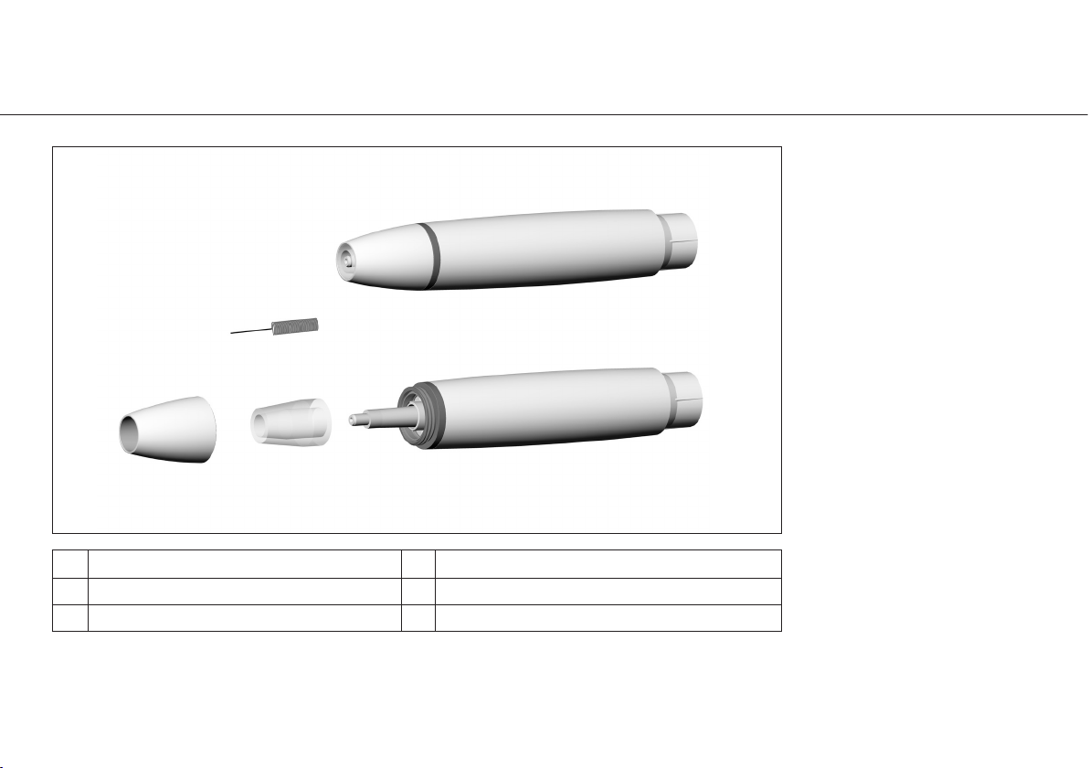
Description
LED Handpiece
Thread Optical fibre
Connection for supply hose Optic outlet
Handpiece cap Nozzle Cleaner
16
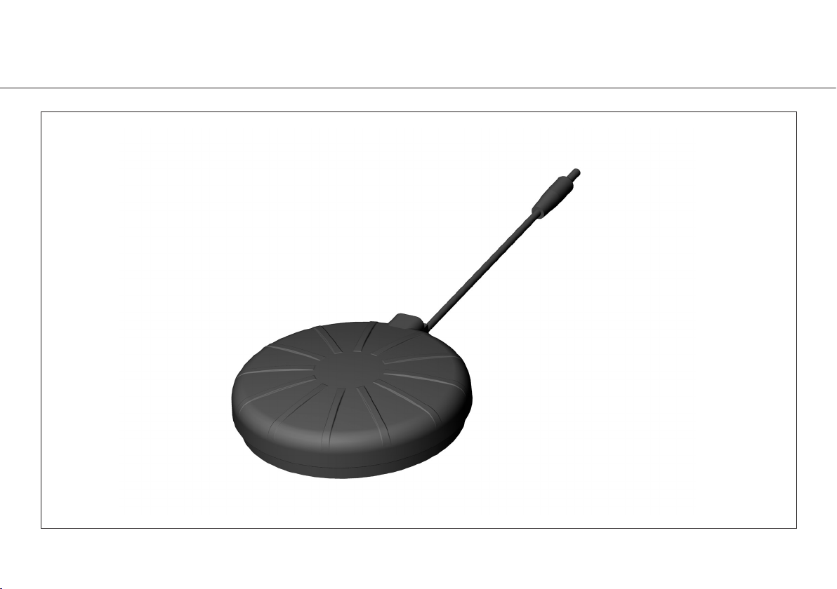
Description Foot control U8007
17
7. Start-up Control unit general
Ensure that the device can be disconnected from the power supply at any time.
Control unit U8200
Push the coolant hose until the limit stop.
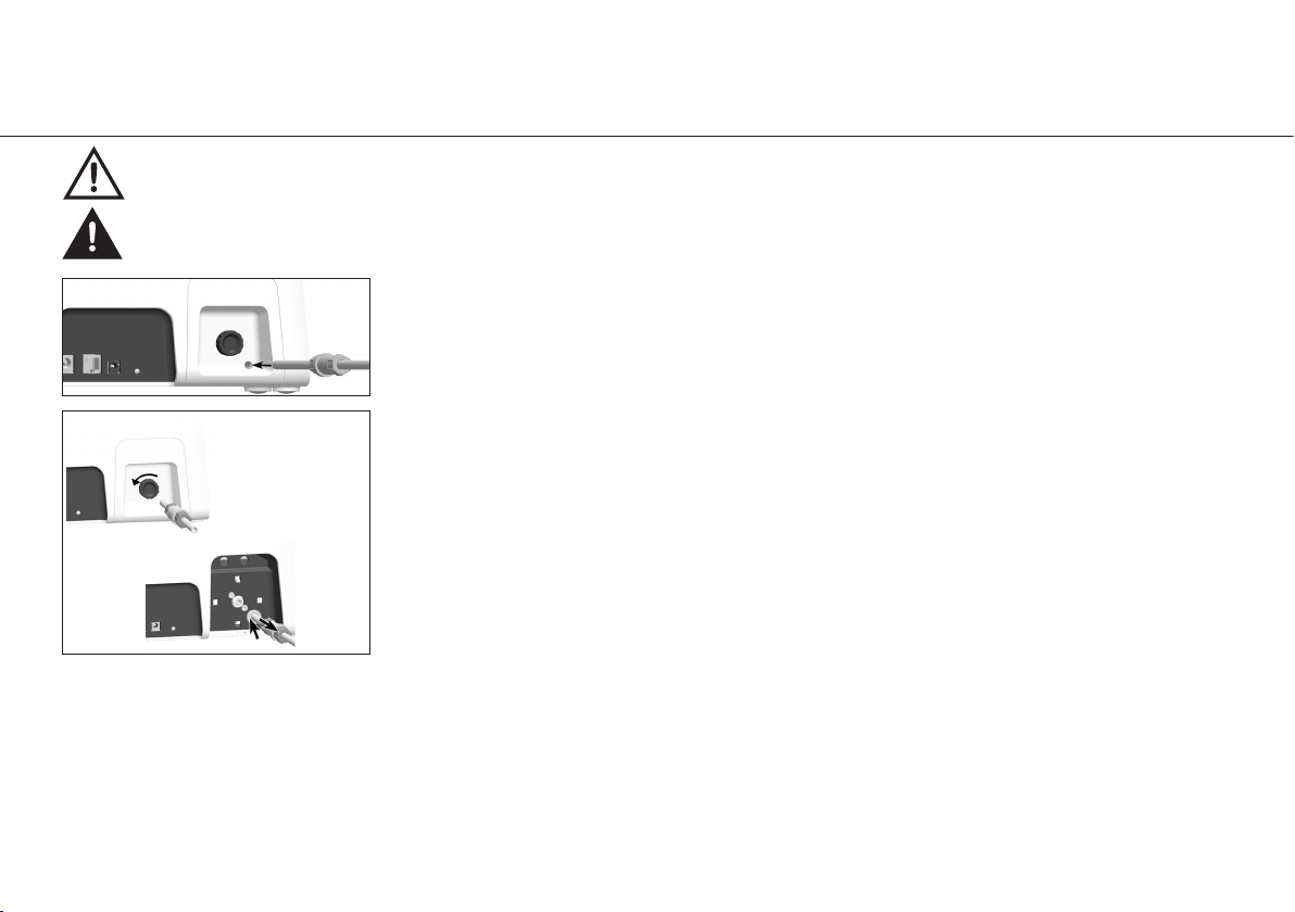
Control unit U8200
Remove the coolant hose
Screw off the coolant regulator.
Uncrew the cover and remove it.
Push the connection ring and simultaneously remove the coolant hose.
Place the device on a flat, level surface.
18
Start-up Control unit general
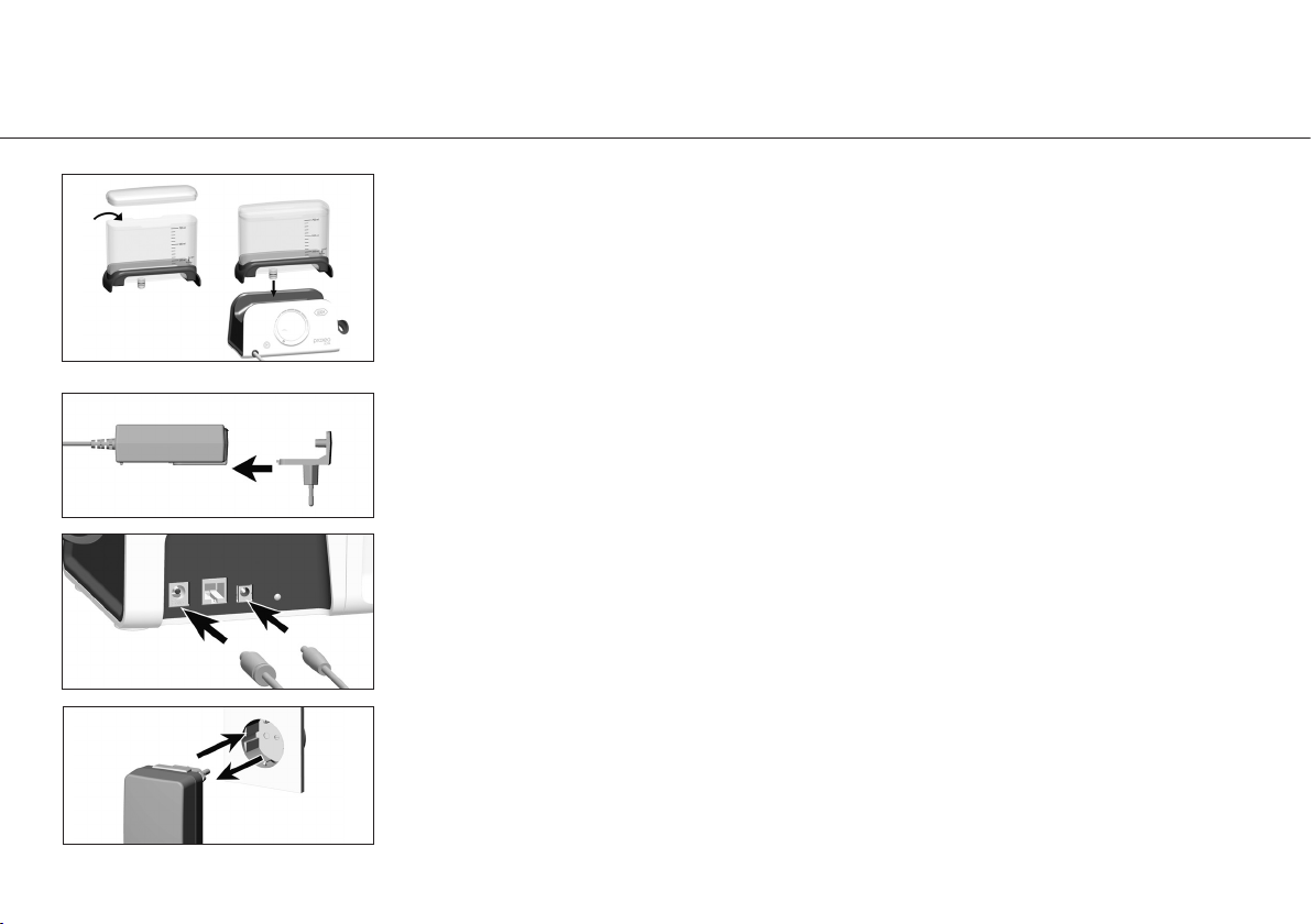
Control unit U8300
Coolant tank
Fill the coolant tank and attach it. The coolant tank snaps audibly into place.
Plug the power supply into a socket.
Pull the power supply out of the socket.
Control unit
Slide the adapter onto the power supply.
Connect the power supply.
Connect the foot control.
19
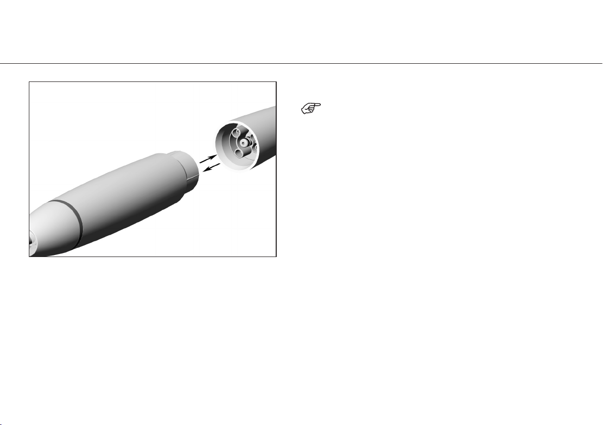
8. Operation Assembly/Removal
Push the handpiece onto the supply hose.
Note the positioning.
Remove the handpiece.

20
Operation Changing the tip
Insert tip with tip changer
Ensure the matching thread system
(at the handpiece, tip changer, tip)!
Position the tip on the thread of the
handpiece.
Turn the tip changer until it audibly engages.
Withdraw the tip changer.
Verify full engagement.
Press the tip with about 1 N (= 100 g)
pressure onto a firm object to test the
loading capacity of the tip.
This manual suits for next models
3
Table of contents
Other iM3 Media Converter manuals


