Trilithic EASyCAP C5020 User manual

DRAFT
EASyCAP
Encoder/Decoder
Operation Manual

DRAFT

DRAFT
EASyCAP Encoder/Decoder - Manual
1
Trilithic Company Profile
Trilithic is a privately held manufacturer founded in 1986 as an engineering and assembly
company that builds and designs customer-directed products for telecommunications, military,
and industrial customers. From its modest beginnings as a t o-man engineering team, Trilithic
has gro n over the years and broadened its offerings of RF and micro ave components by
adding broadband solutions to its product line. This as accomplished ith the acquisition of
components manufacturer Cir-Q-Tel and instruments manufacturer Texscan.
Today, Trilithic is an industry leader, providing telecommunications solutions for major broadband,
RF and micro ave markets around the orld. As an ISO 9000:2001 certified company ith over
40 years of collective expertise in engineering and custom assembly, Trilithic is dedicated to
providing quality products, services and communications solutions that exceed customer
expectations.
Trilithic is comprised of five major divisions:
Broadband Instruments and Systems
Offers test, analysis, and quality management solutions for the major cable television
systems orld ide.
RF Microwave Components
Provides components and custom subsystems for companies specializing in cellular,
military, and other ireless applications.
Emergency Alert Systems
Leading supplier of government-mandated emergency alert systems used by broadcast
TV, cable TV, IPTV, DBS, and radio stations.
XF P
Offers a specialty line of field technical products for cable operators and technicians, as
ell as a line of products for installing electronics in the home of the future.

DRAFT
EASyCAP Encoder/Decoder - Manual
2
HIS PAGE LEF IN EN IONALLY BLANK

DRAFT
EASyCAP Encoder/Decoder - Manual
3
1. General Information .............................................................................................................. 5
Introduction ............................................................................................................................ 5
FCC Certification................................................................................................................... 6
Unpacking and Inspection ...................................................................................................... 6
Claims for Damage in Shipment ............................................................................................ 6
Helpful Website ..................................................................................................................... 7
Where to Get Technical Support ............................................................................................. 7
Ho this Manual is Organized ................................................................................................ 8
Conventions Used in this Manual ........................................................................................... 8
2. Overview ............................................................................................................................... 9
Wiring Recommendations ...................................................................................................... 9
Hard are Overvie .............................................................................................................10
Front Panel Vie ............................................................................................................10
Rear Panel Vie ............................................................................................................ 11
Rear Panel Details .........................................................................................................15
3. Configuration ...................................................................................................................... 19
System Login ....................................................................................................................... 19
Net ork Settings .................................................................................................................20
Net ork Interfaces ..........................................................................................................20
Net ork Time Protocol (NTP) Encoder/Decoder .............................................................22
Date/Time Settings ..............................................................................................................23
CAP Settings.......................................................................................................................24
TCP Feed Settings ........................................................................................................ 25
Alert Text Settings ................................................................................................................26
Accepted Events .................................................................................................................27
Accepted Locations ............................................................................................................. 28
Outgoing Delivery Settings ...................................................................................................29
Encoder/Decoder Settings .............................................................................................30
User Account Settings .......................................................................................................... 31
User Settings .................................................................................................................32
System Administration Settings ........................................................................................... 33
Upgrades ....................................................................................................................... 33
Reboot ........................................................................................................................... 34
Logs .................................................................................................................................... 35
Alert Log ........................................................................................................................ 35
System Log .................................................................................................................... 35
About ................................................................................................................................... 36
Table of Contents

DRAFT
EASyCAP Encoder/Decoder - Manual
4
4. Appendix ............................................................................................................................. 37
Specifications ...................................................................................................................... 37
General Specifications ................................................................................................... 37
Processor and Memory .................................................................................................. 37
Chassis .......................................................................................................................... 37
Communications ............................................................................................................ 37
Audio ............................................................................................................................. 37
Video ............................................................................................................................. 38
General Purpose Inputs and Outputs ............................................................................... 38
Radio Receiver Boards .................................................................................................. 38
AES-EBU Digital Audio Board ....................................................................................... 38
Communications Board .................................................................................................. 38
PCI-Express Expansion Slot (Optional) .......................................................................... 39
Trilithic EAS 2-Year Limited Warranty ................................................................................... 40

DRAFT
EASyCAP Encoder/Decoder - Manual
5
1. General Information
Chapter 1
Introduction
The Trilithic EASyCAP (Model EASyCAP-1) EAS (Emergency Alert System) Encoder/Decoder is
a t o-U rack mounted control center capable of performing manual or automated EAS messaging
for Cable, Broadcast, and Wireline systems, in accordance ith CFR 47 part 11 FCC regulations,
and the EAS Cable Handbook.
The EASyCAP receives EAS messages from up to six audio sources (internal or external),
decodes the FSK EAS message, and operates the target system equipment to replay the
message for vie ers/listeners. In addition, messages can be originated by the user via local or
remote control of the EASyCAP. The EAS Audio sources for the EASyCAP include internal AM/
FM/NOAA radios and external audio inputs that can be connected to any kno n EAS audio
source. EAS Audio is decoded by the internal AFSK circuitry, it is then sorted and interpreted to
determine the type of emergency or test, locations for hich the emergency applies, and other
information supplied in the EAS Header. If a voice message is contained in the EAS message, it
is recorded for possible playback to subscribers. EAS messages then pass through a series of
tests to determine if the message matches predefined, user configurable parameters. If these
tests pass, EAS activation (message playback) to the system occurs. To play an EAS message to
vie ers/listeners, the EASyCAP activates TTLs, Contact Closures, RS-485 data commands, RS-
232 data commands, and several IP based protocols, it also supplies pertinent video and re-
encodes/plays the EAS FSK and recorded audio. The TTLs, Contact Closures, and serial data
commands, and IP protocols activate routing equipment and end-user devices to provide the
emergency audio and video to all vie ers/listeners.
In addition to the EAS messaging capabilities, the EASyCAP records all received and
transmitted messages in its internal log for later retrieval.

DRAFT
EASyCAP Encoder/Decoder - Manual
6
FCC Certification
The Trilithic EASyCAP Encoder/Decoder is certified to comply with 47 CFR, P rt
11 (FCC regul tions) for EAS encoders nd decoders, nd is registered with the
FCC under identific tion number: P4V-EASYCAP-1.
Persu nt to FCC 15.21 of the FCC rules, ch nges not expressly pproved by
Trilithic, Inc. might c use h rmful interference nd void the FCC uthoriz tion to
oper te this product.
This equipment h s been tested nd found to comply with the limits for Cl ss A digit l device,
pursu nt to P rt 15 of the FCC Rules. These limits re designed to provide re son ble protection
g inst h rmful interference in residenti l inst ll tion. This equipment gener tes, uses nd c n
r di te r dio frequency energy nd, if not inst lled nd used in ccord nce with the instructions,
m y c use h rmful interference to r dio communic tions. However, there is no gu r ntee th t
interference will not occur in p rticul r inst ll tion. If this equipment does c use h rmful
interference to r dio or television reception, which c n be determined by turning the equipment off
nd on, the user is encour ged to try to correct the interference by one or more of the following
me sures:
Reorient or reloc te the receiving ntenn .
Incre se the sep r tion between the equipment nd receiver.
Connect the equipment into n output on circuit different from th t to which thereceiver is
connected.
Consult the de ler or n experienced r dio/TV technici n for help.
Unpacking and Inspection
When the EASyCAP Encoder/Decoder rrives, immedi tely inspect the shipping cont iner nd
contents for visible d m ge. Keep ll p cking m teri ls until the equipments intended
perform nce ch r cteristics h ve been verified. If ny of the equipment is d m ged or f ils to
oper te properly due to tr nsport tion d m ge, immedi tely file cl im with the tr nsport tion
comp ny or, if insured sep r tely, with the insur nce comp ny.
E ch EASyCAP Encoder/Decoder will rrive in its own shipping cont iner. The cont iner will, t
minimum, include the following components; EASyCAP Encoder/Decoder & AC Power Cord.
Claims for Damage in Shipment
Cl ims for shipping d m ge should be directed to the shipping nd/or freight delivery service
used. Cl ims should be m de within 7 d ys to insure prompt h ndling of the cl im.

DRAFT
EASyCAP Encoder/Decoder - Manual
7
Helpful Website
The follo ing ebsite contains general information hich may be of interest:
http://www.trilithic.com
Trilithics ebsite contains product specifications and information, tips, release information,
marketing information, Frequently Asked Questions (FAQs), bulletins, and other technical
information. This ebsite can be referenced for product updates.
Where to Get Technical Support
Trilithic technical support is available Monday through Friday from 8:00AM to 5:00PM EST.
Callers in North America can dial 1-317-895-3600 or 1-800-344-2412 (toll free). International
callers should dial 1-317-895-3600 or fax questions to 1-317-895-3613. You can also e-mail
technical support at [email protected].
For quicker support response hen calling or sending e-mail, please provide the follo ing
information:
Your name and your company name
The technical point of contact (name, phone number, e-mail)
The serial number of the EASyCAP Encoder/Decoder
A detailed description of the problem you are having, including any error or information
messages
Before any Trilithic EAS encoder/decoder can be returned for repair, Trilithic ill issue a return
material authorization (RMA) number. NO RETURNED EQUIPMENT WILL BE ACCEPTED
WHICH DOES NOT HAVE AN RMA NUMBER PROMINENTLY DISPLAYED ON THE OUTSIDE
SHIPPING CARTON AND ON THE SHIPPING LABEL. A complete and full description, in riting,
regarding the service issues ith the equipment must be supplied inside the shipping container
ith each piece of equipment for hich an RMA number has been issued.
Hardware or software modifications and changes may occur at any
time during production, shipping, and/or during the equipments life
span. These changes may occur or be implemented by Trilithic,
Inc. without prior written notice or warning.

DRAFT
EASyCAP Encoder/Decoder - Manual
8
Conventions Used in this Manual
This manual has several standard conventions for presenting information.
Connections, menus, menu options, and user entered text and commands appear in bold.
Section names, eb, and e-mail addresses appear in italics.
A OTE is information that will be of assistance to you related
to the current step or procedure.
A CAUTIO alerts you to any condition that could cause a
mechanical failure or potential loss of data.
A WAR I G alerts you to any condition that could cause
personal injury.
How this Manual is Organized
This manual is divided into the follo ing chapters:
Chapter 1, General Information, provides Trilithic contact information and describes ho
this operation manual is structured.
Chapter 2, Overvie gives an overvie of the EASyCAP Encoder/Decoder hard are
and ho it orks.
Chapter 3, Configuration describes the steps necessary to configure the EASyCAP
Encoder/Decoder.
Chapter 3, Appendix describes the specifications and arranty of the EASyCAP
Encoder/Decoder.

DRAFT
EASyCAP Encoder/Decoder - Manual
9
2. Overview
Chapter 2
Wiring Recommendations
Shielded audio ire for all TTL, contact closure, and audio connections
Shielded RS-232 and printer cables
Shielded (coaxial) video cables
Shielded RS-485 data cable
Shielded Category 6 or 7 Ethernet cables for all Ethernet connections.

DRAFT
EASyCAP Encoder/Decoder - Manual
10
21
Hardware Overview
ront Panel View
1. Speaker - Used for monitoring audio inputs and to provide aural feedback during EAS
activations.
2. ouchscreen LCD display - Provides visual feedback during programming, setup,
monitoring, and activations and it is used for local control of the EASyCAP and access
to the on-board menu system.
The keypad and LCD display provide an on-board menu system,
allowing for a limited amount of configuration, tests, and
encoding functions. A secure web interface provides more
comprehensive configuration and control of the encoder/
decoder.

DRAFT
EASyCAP Encoder/Decoder - Manual
11
Rear Panel View
345
91078 11 1312
2
1
1. PCIe Expansion Slot (Optional) - This is a PCIe expansion slot that ill accomodate
a 1, 4, or 16 lane PCIe card. This is reserved for future use.
2. AES-EBU Digital Audio - This is
an AES-EBU expansion slot that
accomodates t o AES-EBU
digital audio s itches. Each s itch
provides a pair of channels using
110 Ohm XLR connections. Each
s itch provides a pair of channels
using 110 Ohm XLR connections. Internal s itches are provided to replace the AES-
EBU program audio ith alert audio. Alert audio automatically locks to the incoming bit
rate and sample rate (up to 192 kHz). Configurable as a s itch or an audio source.
DRAFT
EASyCAP Encoder/Decoder - Manual
12
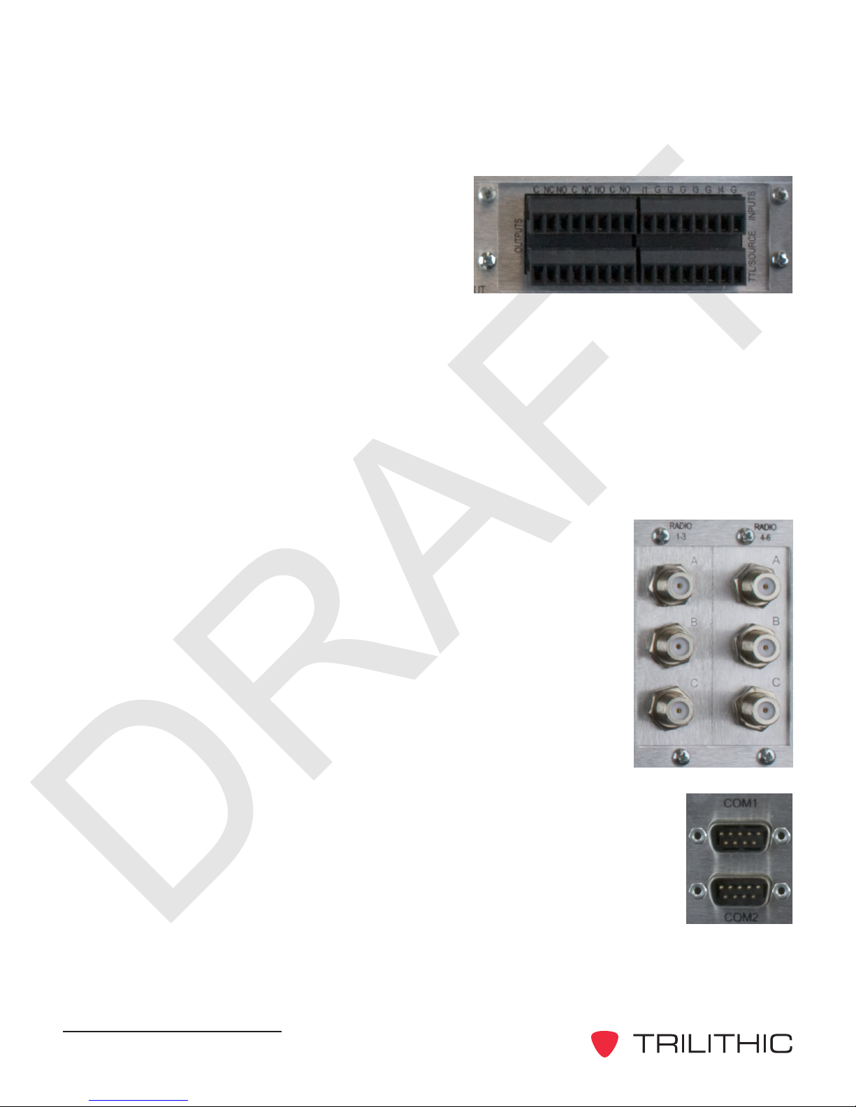
3. General Purpose Inputs/Outputs - The
EASyCAP Encoder/Decoder comes ith
six (6) general purpose outputs, four (4)
general purpose inputs, and t o (2) TTL
outputs:
General Purpose Outputs - This
provides a programmable contact
closure output (s itch) used to activate equipment to route EAS message audio
and video, sound alarms, etc. during EAS activations.
General Purpose Inputs - This provides a means for operators or external
automation equipment to trigger or abort events (such as message
retransmission) ithin the EASyCAP.
L Outputs - These provide a five (5) volt DC signal (and ground connection)
used to activate EAS audio and video routing equipment. A current source is
also provided.
4. Radios 1-3 - This is an AM/FM/NOAA radio receiver board ith
three radio tuners (A, B, and C) per board.
5. Radios 4-6 - This is an AM/FM/NOAA radio receiver board ith
three radio tuners (A, B, and C) per board.
6. COM1 - (RS-232 Connection) Provides an RS-232 compliant serial
data connection to provide streaming EAS information to external
character generators, as ell as to provide a serial input/output for the
EASyCAP.
7. COM2 - (RS-232 Connection) Provides an RS-232 compliant serial
data connection to provide streaming EAS information to external
character generators, as ell as to provide a serial input/output for the
EASyCAP.

DRAFT
EASyCAP Encoder/Decoder - Manual
13
8. Communications Board - This is a communications
board that is equipped ith the follo ing:
One 10/100 Ethernet Port
One Telephone Modem Port
One RS-485 Port
9. Ethernet - T o 10/100/1000 Ethernet Ports. Provides an Ethernet
interface for remote configuration, operation, and maintenance of
the EASyCAP, as ell as providing digital EAS messages across a
net ork to a stations audio and video equipment and allo ing
distant monitoring stations to be transported over Ethernet to the
EASyCAP.
USB Ports - Four USB ports are provided for USB communication.
10. CG VIDEO IN - NTSC video input connection (normal station video) for the
character generator.
11. CG VIDEO OU - NTSC video output connection (EAS modified station
video) to the transmitter.

DRAFT
EASyCAP Encoder/Decoder - Manual
14
12. Audio Interface Board - This provides six
(6) balanced 600 Ohm audio inputs, one
(1) line input, one (1) line output, t o (2)
EAS audio outputs, one (1) program audio
input, and one (1) program audio output.
Audio Inputs 1-6 - This provides a
means for connecting up to six (6)
external audio sources for EAS
monitoring, or for supplying audio for transmission.
Audio Outputs & Line Output - This provides EAS audio outputs that may be
distributed for EAS messaging and monitoring.
Line Input - This provides a connection for a line-level microphone input for
message origination.
Input - This provides a balanced stereo audio input ith hich a system/station
may supply normal program audio. This audio is replaced by the EASyCAP
during messaging.
Output - This provides EAS information audio during messaging, other ise it
contains the Input signal.

DRAFT
EASyCAP Encoder/Decoder - Manual
15
Rear Panel Details
COM1 (RS-232 connection) - 9-pin RS-232C DTE interface used for configuration, control,
and log retrieval from a PC or laptop via a 9-pin NULL-MODEM cable.
Pin 2: Receive data*
Pin 3: Transmit data*
Pin 4: Data terminal ready
Pin 5: Signal ground*
Pin 6: Data set ready
Pin 7: Request to send
Pin 8: Clear to send
Pin 9: Ring indicator
* Required signal
COM2 (RS-232 connection) - 9-pin RS-232C DTE interface used for control over external
character generators/video insertion equipment.
Pin 2: Receive data
Pin 3: Transmit data
Pin 4: Data terminal ready
Pin 5: Signal ground
Pin 6: Data set ready
Pin 7: Request to send
Pin 8: Clear to send
Pin 9: Ring indicator
Radios 1-3 - Provides three AM/FM/NOAA tuners ith independent antenna inputs.
Radios 4-6 - Provides three AM/FM/NOAA tuners ith independent antenna inputs.

DRAFT
EASyCAP Encoder/Decoder - Manual
16
Audio switch (optional) - Line-level balanced stereo audio s itch used to replace normal
programming audio ith EAS audio during EAS activations.
Input - Connect the normal program audio source to the audio s itch input.
Output - Connect the audio s itch output to the transmitter.
Audio switch signal lines (Definition of audio s itch signals, from left to right)
(-) Negative balanced program audio input for left channel
(+) Positive balanced program audio input for left channel
(G) Ground
(-) Negative balanced program audio input for right channel
(+) Positive balanced program audio input for right channel
(-) Negative balanced program audio/EAS output for left channel
(+) Positive balanced program audio/EAS output for left channel
(G) Ground
(-) Negative balanced program audio/EAS output for right channel
(+) Positive balanced program audio/EAS output for right channel
CG VIDEO
VIDEO IN - Connect normal programming video to the VIDEO IN.
VIDEO OU - Connect the VIDEO OUT to the transmitter.
Audio inputs - Six balanced line-level audio inputs are provided for additional EAS
monitoring sources. These inputs can be connected to EAS audio sources such as TV tuners,
satellite receivers, or external radio tuners.
(+) Positive baseband input for the respective channel
(-) Negative baseband input input for the respective channel
(G) Ground
Audio outputs - EAS audio is available on t o line-level balanced audio outputs. Use these
outputs to connect to EAS distribution/routing equipment or studio speakers. This is the audio
generated by the EASyCAP during EAS activation.
(+) Positive baseband input for the respective channel
(-) Negative baseband input input for the respective channel
(G) Ground

DRAFT
EASyCAP Encoder/Decoder - Manual
17
Contact closures - Used for distribution/routing equipment that requires a contact closure for
activation, or for operator alarms during EAS operations.
(C) Common contact
(NC) Normally-closed contact
(NO) Normally-open contact
Ethernet and elephone Interface - Provides an Ethernet interface for remote configuration,
operation, and maintenance of the EASyCAP, as ell as providing digital EAS messages
across a net ork to a stations audio and video equipment and allo ing distant monitoring
stations to be transported over Ethernet to the EASyCAP. In addition to the Ethernet, a
telephone interface allo s DTMF or data communication for remote control of the EASyCAP,
and remote generation of emergency messages.
RS-485 - This is a standard 1/8th load RS-485 communications port that is provided for
controlling external character generators.
AES/EBU Audio - Provides independent synchronized AES/EBU audio s itches for in-line
replacement of programming audio during EAS operations. If an input is provided (from a
station source), the output sample rate ill be equal to the input sample rate. If no input is
provided, the output sample rate ill be 48KHz.
AES/EBU input 110 W XLR female
Pin 1: Ground/drain
Pin 2: Balanced +
Pin 3: Balanced -
AES/EBU output 110 W XLR male
Pin 1: Ground/drain
Pin 2: Balanced +
Pin 3: Balanced -

DRAFT
EASyCAP Encoder/Decoder - Manual
18
Contact closure inputs - provide a means for controlling the EASyCAP using automation
equipment or operator s itchboard.
Input 1, abort - When closed, causes any EAS message being received to be
disregarded, and any EAS message being transmitted to be stopped. The EASyCAP ill
attempt to stop all video displays and audio s itches, then return to monitoring for EAS
messages.
(G) Contact ground
(I1)Approximately 3.75 mA pull-up opto-isolated input (5 Volt @ 0 mA)
Input 2, trigger - When closed, causes any EAS message aiting to be transmitted to
begin transmission, regardless of the state of the hold-off input (input 3).
(G) Contact ground
(I2)Approximately 3.75 mA pull-up opto-isolated input (5 Volt @ 0 mA)
Input 3, hold-off: Configurable for active-open or active-closed. When active, this
prohibits any EAS message aiting to be transmitted from starting transmission except by
the trigger input (Input 2), user activation, or the event delay time-out (configurable).
(G) Contact ground
(I3)Approximately 3.75 mA pull-up opto-isolated input (5 Volt @ 0 mA)
Input 4, trigger RW : When momentarily closed, causes a required eekly test to be
transmitted.
(G) Contact ground
(I4)Approximately 3.75 mA pull-up opto-isolated input (5 Volt @ 0 mA)
Table of contents
Other Trilithic Media Converter manuals


