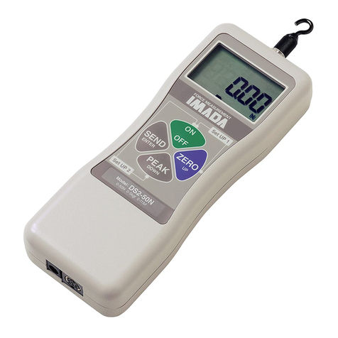
Imada ZTS Series User manual

Dinamómetro Digital Serie ZTS

INSTRUCTION MANUAL
Digital Force Gauges
Standard Models: ZTS, ZTS-DPU, ZTS-LM
07/18
with Electro Luminescent (EL) Display
Multi-Language Menus and
ZT Logger Data Acquisition Software
V339644

page 2
INTRODUCTION . . . . . . . . . . . . . . . . . . . . . . . . . . . . . . . . . . . . . . . . . . . . .3
PRECAUTIONS . . . . . . . . . . . . . . . . . . . . . . . . . . . . . . . . . . . . . . . . . . . . . . .3
OVERVIEW . . . . . . . . . . . . . . . . . . . . . . . . . . . . . . . . . . . . . . . . . . . . . . . . . . .4
PREPARATION
1. Remote Sensor Models . . . . . . . . . . . . . . . . . . . . . . . . . . . . . . . . . . . . . . . . . . .5
2. Charging the Ni-MH Battery . . . . . . . . . . . . . . . . . . . . . . . . . . . . . . . . . . . . . . .5
COMMON PROGRAMMING TASKS
1. Setting Date and Time . . . . . . . . . . . . . . . . . . . . . . . . . . . . . . . . . . . . . . . . . . . .6
2. Selecting Units . . . . . . . . . . . . . . . . . . . . . . . . . . . . . . . . . . . . . . . . . . . . . . . . .7
3. Reversing the Display for Test Stand Mounting . . . . . . . . . . . . . . . . . . . . . . . . .7
4. Programming Go/No Go Setpoints . . . . . . . . . . . . . . . . . . . . . . . . . . . . . . . . . .8
5. Setting LOCK . . . . . . . . . . . . . . . . . . . . . . . . . . . . . . . . . . . . . . . . . . . . . . . . . . .9
OPERATION
1. Programming . . . . . . . . . . . . . . . . . . . . . . . . . . . . . . . . . . . . . . . . . . . . . . . . . .10
2. Attachments . . . . . . . . . . . . . . . . . . . . . . . . . . . . . . . . . . . . . . . . . . . . . . . . . .10
3. Peak or Real 10me Measurement Mode . . . . . . . . . . . . . . . . . . . . . . . . . . . . .10
4. Tare . . . . . . . . . . . . . . . . . . . . . . . . . . . . . . . . . . . . . . . . . . . . . . . . . . . . . . . . .10
STORING AND COLLECTING DATA
1. Recalling Stored Data . . . . . . . . . . . . . . . . . . . . . . . . . . . . . . . . . . . . . . . . . . .11
2. Clearing Stored Data . . . . . . . . . . . . . . . . . . . . . . . . . . . . . . . . . . . . . . . . . .11-12
3. Downloading Data from Memory . . . . . . . . . . . . . . . . . . . . . . . . . . . . . . .12-13
4. Optional Data Acquisition Accessories . . . . . . . . . . . . . . . . . . . . . . . . . . . . . .13
OUTPUT
1. Communications Port . . . . . . . . . . . . . . . . . . . . . . . . . . . . . . . . . . . . . . . . . . .14
2. Data Output Formats . . . . . . . . . . . . . . . . . . . . . . . . . . . . . . . . . . . . . . . . . . . .15
3. Force Unit Codes . . . . . . . . . . . . . . . . . . . . . . . . . . . . . . . . . . . . . . . . . . . . . . .15
4. RS232C & USB Commands . . . . . . . . . . . . . . . . . . . . . . . . . . . . . . . . . . . . .16-17
5. Backward Compatible RS232C & USB Commands . . . . . . . . . . . . . . . . . .18-19
ZT LOGGER
1. Installation . . . . . . . . . . . . . . . . . . . . . . . . . . . . . . . . . . . . . . . . . . . . . . . . .20-24
2. Operation . . . . . . . . . . . . . . . . . . . . . . . . . . . . . . . . . . . . . . . . . . . . . . . . . .24-29
SPECIFICATIONS/DIMENSIONS . . . . . . . . . . . . . . . . . . . . . . . . .30-31
1
2
3
4
5
6
8
9
10
7
PROGRAMMING REFERENCE SECTION . . . . . . . . . . . . . . . . .32-43
11
Using Multi Display . . . .32-33
Turn on the gauge, then press (do not hold) the MENU key
to highlight the upper section. Press the arrow keys to cycle
selectable data. Press the MENU key to select the data and
highlight the lower section. Press the arrow keys to cycle
selectable data then press the MENU key to select and exit.
Program Menu
Turn ON the gauge. Press and hold MENU two seconds to
enter the Program Menu. Press an arrow key to access the
following functions.
High Low Setpoints . . . . . . . . . .34
Peak Functions . . . . . . . . . . .34-35
Internal Memory . . . . . . . . . . . .35
Auto Zero Timer . . . . . . . . . . . . .36
Sound . . . . . . . . . . . . . . . . . . . . .36
Display Functions . . . . . . . . .37-38
Date and Time . . . . . . . . . . . . . .39
Setup Menu
Press and hold MENU, then press ON/OFF to turn ON the
gauge and enter the Setup Menu. Press an arrow key to
access the following functions,
Units . . . . . . . . . . . . . . . . . . . . . .40
+/– Indicator . . . . . . . . . . . . . . .40
Sensitivity . . . . . . . . . . . . . . . . . .41
Zero/Tare Reset . . . . . . . . . . . . .41
Send Functions . . . . . . . . . . . . . .42
Date Format . . . . . . . . . . . . . . . .42
Language . . . . . . . . . . . . . . . . . .43
Setting LOCK . . . . . . . . . . . . . . .43

page 3
INTRODUCTION
Imada ZTS Series high performance, digital force gauges include all
the standard features: selectable real time and peak measuring
modes, selectable measuring units, lbf (ozf), kgf (gf), N, high/low set-
points with color-coded LED indicators for Go/No Go testing, 1,000
data memory, USB, RS-232 and Digimatic output.
Additionally, ZTS gauges incorporate user-friendly, multi-language
program menus, highly visible EL (electro luminescent) displays, ZT
Logger software which downloads gauge memory and can set all
gauge functions and actual 2,000 data/second processing and trans-
mission capability, not just the peak data.
1
PRECAUTIONS
1. WARNING!! Test samples and fixtures can break or shatter,
wear eye and body protection to avoid injury.
2. WARNING!! REGARDLESS of whether the unit is ON or OFF,
DO NOT exceed the capacity of the gauge. At 110% of the
rated capacity, the overload LED indicator flashes to warn.
NEVER exceed 200% of the rated capacity, or the load cell will
be damaged.Avoid shock load.
3. When mounting ZTS Series, use M4 mounting screws with a
maximum insertion depth of 5 mm into the gauge. For high
capacity gauges use the supplied mount-
ing hardware only.
4. Measure in line tension and compression
forces only. DO NOT attempt to mea-
sure forces perpendicular to the measur-
ing shaft – damage to load cell and/or
shaft may result.
5. Hand tighten attachments only. DO NOT use tools.
6. Make sure this gauge and all peripherals are powered down
before attaching any cables.
7. DO NOT disassemble the gauge. Disassembly voids warranty.
2
00.0
00.0

page 4
OVERVIEW
3
LED INDICATORS: When high/low setpoints are
set, LED indicates below (–NG), within (OK), or
above setpoint value (+NG)
KEYPAD
ON/OFF: Press to turn ON, hold more than one
second to turn OFF
SEND: Press to send data to internal gauge
memory, press and hold for data hold
PEAK: Press to toggle Peak and Real Time
ZERO: Resets the display, tares attachments
MENU: Press to select data on Multi Display.
(see pages 32-33)
Program Menu: with gauge ON, press and
hold two seconds to enter Program Menu.
Setup Menu: with gauge OFF, press and hold,
then press ON/OFF to enter Setup Menu.
1
2
3
4
5
123.4
Battery status indicator
Auto zero icon: appears when Auto Zero is set.
Force value
Peak indicator
Peak hold: Appears when external hold signal is
active or SEND is pressed.
Units
1
2
5
6
4
3
Peak indicator Force value
4 5 Units
6
MEASURING SHAFT
KEYPAD
EL DISPLAY
USB PORT
I/O PORTS
LED INDICATORS
AC ADAPTER
PORT
2
4
1
3
5
1 2
1 2
3
4
65
3
5
4
6
7
See page 37 to switch between
Multi and Single display.
MULTI DISPLAY
Upper Section
Lower Section
Select data: Peak value, Force level, Memory
number/value, High/low setpoints (see pages 32-33).
7
Middle Section
Battery status indicator
Auto zero icon: appears when Auto Zero is set.
Select data: Date, Time, Stored memory data,
Measurements over high setpoint (see pages 32-33).
1
2
3
SINGLE DISPLAY

page 5
PREPARATION
1.Models ZTS-DPU/LM with Remote Sensors
1. To connect the remote sensor to the ZTS
display unit, rotate the connector to
match the groove with the key, then push
it in until positive connection is made.
2. To disconnect, hold the ribbed cover of the
connector and pull out.
DO NOT TWIST OR PULL THE CABLE!
4
ROTATE CONNECTOR TO MATCH THE
GROOVE WITH THE KEY AND PUSH IN.
HOLD RIBBED COVER AND PULL OUT.
DO NOT TWIST OR PULL CABLE!
2.Charging the Ni-MH Battery
Power shuts off after 10 minutes of non-use. Recharge the battery
when the icon shows a single bar .A full charge takes about two
hours.When fully charged the icon appears and charging stops.
Auto shut off is bypassed when used with the AC adapter/charger.
The battery also charges when connected to a computer USB port.
1. Push ON/OFF to turn off power.
2. Only use IMADA AC adapter/charger (ADW6010) with the proper
115VAC or 230VAC plug adapter. Plug into the correct AC output.
Turn ON the gauge.The display flashes until the battery is charged.
Remote Sensors
IMPORTANT: Both gauge and remote sensor
must have the same serial numbers.
DPU both tension and compression
Low capacity: Box Type (±0.2% F.S.; ±1 LSD)
High capacity: S Type (±0.2% F.S.; ±1 LSD;
ZTS-DPU-2200, ZTS-DPU-4400, ±0.5% F.S., ±1 LSD)
LM compression only (±0.5% F.S.; ±1 LSD)
IMPORTANT:
1. Do not apply load to back of cell.
2. Load applying surface must be flat.
LM
1. DO NOT APPLY
LOAD HERE.
BOX TYPE
DPU
‘S' TYPE
2.
FLAT SURFACE NOT FLAT

page 6
1.Date and Time (optional)
1. Press ON/OFF to turn ON the
gauge, then press and hold
MENU two seconds to enter
the Program Menu. Press the
down arrow key to highlight
Date and Time, then press the
right arrow key to select.
2. Press the right arrow key to
select Date Set.
3. Press the up/down arrows to
select the year and press
MENU to save. Repeat this
step for month and day.
4. Press the up/down arrow
keys to select Time Set, then
press the right arrow key.
5. Press the up/down arrows to
select the hour and press
MENU to save and repeat
this step for minute.
6. Press the left arrow key until the door icon #appears, then press
and hold MENU two seconds to exit. Or press the left arrow
key and when ‘Exit Menu’ appears, press MENU to exit.
COMMON PROGRAMMING TASKS
5
Hour
{
09
} Enter@
Date & Time
< Date Set >
Time Set
Date & Time
Date Set
< Time Set >
Year
{
13
} Enter@
Month
{
03
} Enter@
Day
{
31
} Enter@
Minute
{
00
} Enter@
Program Menu
Display Functions
# Date and Time >
High Low Setpoints

page 7
2.Selecting Units
1. Turn OFF the gauge. Press and hold MENU,
then press ON/OFF to turn ON the gauge
and enter the Setup Menu. Units is highlighted,
press the right arrow key to select.
2. Force Units is highlighted, press the right
arrow key to select.
3. Press the up/down arrow keys to select Units
and press MENU to input your selection.
4. Press the left arrow key until the door icon #
appears, then press and hold MENU two sec-
onds to exit. Or press the left arrow key and
when ‘Exit Menu’ appears, press MENU to exit.
3.Reversing the Display (optional)
Reverse the display for test stand mounting.
1. Press ON/OFF to turn ON the gauge, then
press and hold MENU two seconds to enter
the Program Menu. Press the down arrow key to
highlight Display Functions, then press the
right arrow key to select.
2. Press the up/down arrow keys to highlight
Reverse Display and press the right arrow key
to select.
3. Press the up/down arrow keys to select and
press MENU to input your selection.
4. Press the left arrow key until the door icon #
appears, then press and hold MENU two sec-
onds to exit. Or press the left arrow key and
when ‘Exit Menu’ appears, press MENU to exit.
The selected display is retained as the default.
Units
< Force Units >
Force Units
{
N
<Back } Enter@
Setup Menu
Language
# Units >
+/- Indicator
Reverse Display
{
OFF
<Back } Enter@
Display Functions
Brightness
< Reverse Display >
Auto Shut Off
Program Menu
Sound
# Display Functions >
Date and Time
Permanent Test Stand Installation
If your force gauge is permanently installed to a test
stand, carefully adhere the enclosed reverse display
decal over the keypad to make it easier to read.
REVERSE
DISPLAY OFF
REVERSE
DISPLAY ON

page 8
4.Programming Setpoints (optional)
Program High and Low setpoints for easy Go/No Go testing.
1. Press ON/OFF to turn on the gauge.
2. Press and hold the MENU key two
seconds to enter the Program Menu.
3. Press the up or down arrows on the
keypad to highlight High
Low Setpoints, then press the
right arrow key.
4. When High appears press the
right arrow key to set the
High setpoint.
5. Press the up/down arrow
keys to change the high set-
point and press MENU to save and return to High Low Setpoints.
6. Press the down arrow to highlight Low and then press the right
arrow key.
7. Press the up/down arrow keys to change the low setpoint and
press MENU to save.
8. Press the left arrow key until the door icon #appears, then press
and hold MENU two seconds to exit. Or press the left arrow
key and when ‘Exit Menu’ appears, press MENU to exit.
High Low Setpoints
< High >
Low
High Low Setpoints
High
< Low >
High
{
10.0
<Back } Enter@
Low
{
5.0
<Back } Enter@
For example, if 5 lbf is set as Low and 10
lbf as High, the ORANGE LED lights for
measurements less than 5 lbf (–NG).
GREEN lights between 5–10 lbf (OK) and
RED lights over 10 lbf (+NG). Setpoint out-
put is available through the
Communications port (see page 14).
Program Menu
Date and Time
# High Low Setpoints >
Peak Functions

page 9
CAUTION
Apply tension or compression
forces in line with the
measuring shaft.
00.0
00.0
!
5.Setting LOCK (optional)
Prevents gauge settings from being changed.
1. Turn OFF the gauge. Press and hold MENU,
then press ON/OFF to turn ON the gauge
and enter the Setup Menu.
2. Press the up or down arrows on the keypad to
highlight Setting LOCK, then press the right
arrow key.
3. Press the up/down arrow keys to select ON/OFF and press
MENU to input your selection.
6. Press the left arrow key until the door icon #appears, then press
and hold MENU two seconds to exit. Or press the left arrow
key and when ‘Exit Menu’ appears, press MENU to exit.
Setting LOCK
{
OFF
<Back } Enter@
Setup Menu
Language
# Setting LOCK >
Units

page 10
1.Programming
Select units, reverse display and set the high/low setpoints if
required, using the steps on pages 6-9.
2.Attachments
Hand tighten attachments to the shaft. Do not use tools!
3.Measurement Mode
Real Time Measurement
Press ON/OFF to turn on the gauge.The gauge automatically
enters real time mode and displays transient force values.
Peak Measurement
Press ON/OFF to turn on the gauge. Press PEAK to capture
peak measurements. In Multi display mode ‘P’ is displayed and in
Single display mode ‘Peak’ is displayed. Peak force values do not
change until a higher value is measured. Press PEAK again to
return to real time.
OPERATION
6
‘Or Peak’ is the factory default and captures either peak com-
pression or tension measured during a test.
‘And Peak’ captures both peak compression and peak ten-
sion (See page 34 for programming instructions).
When ‘And Peak’ is programmed press PEAK and ‘+P’ is dis-
played. Press PEAK again and ‘–P’ is displayed.
‘+P’ displays the compression peak captured during a test;
press PEAK to display the tension peak.
‘–P’ displays the tension peak captured during a test; press
PEAK to display the compression peak.
4.Tare and Zero
‘All Reset’ is the factory default and tares and zeroes the display.
Press ZERO to zero the display and tare the weight of a preload
or attachment.
If you need to zero without tare see page 41 ‘Peak Only’.

1. Press ON/OFF to turn on the gauge.
2. Press and hold the MENU key two seconds
to enter the Program Menu.
3. Press the up or down arrow keys to highlight
Internal Memory, then press the right arrow key.
4. Press the up or down arrow keys to highlight
Data Recall and press the right arrow key.
5. Press the up or down arrow keys to view
stored data. If no data is stored ‘–’ is displayed.
6. Press the left arrow key until the door icon #
appears, then press and hold MENU two sec-
onds to exit. Or press the left arrow key and when ‘Exit Menu’
appears, press MENU to exit.
page 11
STORING AND COLLECTING DATA
Press SEND during measurement, in Peak or Real Time mode, to store
a value. Up to 1,000 force values may be stored in gauge memory.
Press SEND when gauge and PC are connected with included USB
cable and data is stored in gauge memory and transmitted to the PC.
Use included ZT Logger to collect and display force data (see page 20).
7
1.Recalling Stored Data
{ No. 23 }
6.0 N
<Back
Internal Memory
< Data Recall >
Data Delete
Program Menu
Peak Functions
# Internal Memory >
Auto Zero Timer
Last Data Delete
1. Follow Recalling Stored Data steps 1-3.
2. Highlight Data Delete and
press the right arrow key.
3. Press the up/down arrow keys
and select Last Data Delete.
4. The last data appears, press
the MENU key to delete it.
If no data is stored ‘–’ is
displayed.
5. Follow Recalling Stored Data
step 6 to exit the menu.
2.Clearing Stored Data Internal Memory
Data Recall
< Data Delete >
Data Delete
{
Last Data Delete
<Back } Clear@
Data Delete
{
All Data Delete
<Back } Clear@
No. 23
6.0 N
<Back Clear@

page 12
3.Downloading Data from Memory
Choose between the following download methods.
1. USB Data Download from Memory
1) Connect the gauge and computer receiv-
ing data with the USB cable.
2) Turn on the gauge and ZT Logger.
3) Under the Data menu, select Import
Gauge Memory.The gauge memory will fill the Data Table
which can be saved as a CSV file.
2. RS-232C Data Download from Memory
Connect the gauge and device receiving data with a CB-208 cable.
All functions can be duplicated remotely by using the RS-232C
interface. Commands must be sent in uppercase ASCII character
format followed by a carriage return [CR].
RS-232C Signal: 8 data, 1 stop, no parity. Baud Rate: 19,200 bps
Refer to the tables on pages 16-19 for ASCII commands.
3. Mitutoyo Digimatic Signal
Connect the CB-308 cable to the communications port and the
device receiving the data. Set up parameters as instructed from
the Mitutoyo processor manual.
4. ±2 VDC Analog Signal
Connect the CB-108 analog cable and
communications port receiving the
voltage signal.Voltage comes through
the D/A converter and resets to zero
when a tare function is performed.
Voltage ±2V
Update 2,000 times/sec
Zero offset 20mV maximum
Span error ±1%
Load Impedance 1KΩor higher
Specifications
All Data Delete
1. Follow Recalling Stored Data steps 1-3, page 11.
2. Highlight Data Delete and press the right arrow key.
3. Press the up/down arrow keys and select All Data Delete.
4. Press the MENU key to clear and a confirmation screen
appears. Press the MENU key again to clear all the data.
5. Press the left arrow key until the door icon #appears, then press
and hold MENU two seconds to exit. Or press the left arrow
key and when ‘Exit Menu’ appears, press MENU to exit.

5. External Power ON/OFF (Same as ON/OFF key function)
Connecting #24 (EX_Power) and #30 (GND) of the communications
port turns ON the gauge and connecting #24 (EX_Power) and
#30 (GND) while #29 (Shift) and #30 (GND) are connected
turns OFF the gauge.
6. External Zero (Same as ZERO key function)
Connecting #25 (EX_ZERO) and #30 (GND) of the communications
port resets the force display. (Tare, peak reset, or peak reset only
are dependent on the Zero/Tare Reset settings, see page 41).
7. External Send (same as the SEND key function)
Connecting #26 (EX_SEND) and #30 (GND) of the communica-
tions port sends data to gauge memory (up to 1,000 data) and an
external device and holds the display while the signal is closed.
8. External Peak (same as PEAK key function)
Connecting #27 (EX_PEAK) and #30 (GND) of the communications
port cycles real time, compression peak and tension peak.
page 13
Use contact closure only and DO NOT apply voltage
to #24 through #30 port pins.
!
4.Optional Data Acquisition Accessories
SW-1 Data Acquisition Software
Capture and analyze force data from gauges with an RS-232 port.A
log of all the data is displayed along with a graph and statistics.
ZT-R Force Recorder Software
Records and processes 2,000 data per second from ZTS gauges and
generates a force profile graph with statistics. Zoom in to examine
force vs. time values at individual data points. Select part of the graph
to detect the first peak or generate statistics for that time interval.
Align and compare multiple graphs. Save graphs or export data to CSV.
Cables
CB-108 10' Analog cable
CB-208 10' RS-232C cable, 9 pin female
CB-308 10' Digimatic Cable

page 14
PIN# Signal Description
1 -NG -NG Output Signal (Note 1)
2 OK OK Output Signal (Note 1)
3 +NG +NG Output Signal (Note 1)
4
5
6 OVL Over Load Output (Note 1)
7 READY Output while Measuring (Note 1)
8 OUT_GND Signal ground for Pins 1 to 7
9 ANALOG OUT 2
10 ANALOG GND 2
11 ANALOG OUT 1
12 ANALOG GND 1
13 TXD
14 RXD
15 RS_GND
16 NC
17 NC
18 NC
19 REQ
20 RDY
21 CLK
22 DATA
23 GND
24 EX_Power Power On / Power Off with shift input (Note 2)
25 EX_ZERO Zero force with shift input (Note 2)
26 EX_SEND Same function as SEND switch (Note 2)
27 EX_PEAK Same function as PEAK switch (Note 2)
28 Rec Data record control (Note 2)
29 Shift Shift input (Change EX_Power and
EX_ZERO input function) (Note 2)
30 IN_GND Signal ground for Pins 24 to 29
31 MARK MARK Input
32
33
34
35
36 +5V
37 GND
Note 1: Pins 1 to 7 are NPN open collector output (30VDC and 25mA maximum)
Note 2: Pins 24 to 29 are inputs for non-voltage contact or NPN open collector.
Direct Analog Output (Optional)
D/A convertor Analog output
Serial Output (RS232C)
Do not use (Factory use only)
Do not use
Digimatic Output
Power supply +5V 200mA max
1~7
+V
RL
8
30V
25mA
OUTPUT CONNECTION
INPUT CONNECTION
24~29, 31
10mA
30
1.Communications Port
OUTPUT
8
37 PIN CONNECTOR

page 15
2.Data Output Formats
Data Output Format [Q][±fffff][±ddddddd][P][L][C][S][X][CR]
Memory Data Output Format m[±fffff][±ddddddd][P][L][C][S][YY][MM][DD][hh][mm][ss][CR]
Q Type of Data f: Continuous data output (2000 data/sec)
I: Continuous data output (10 data/sec)
a: Continuous +peak data
h: Continuous –peak data
r: Real time data
p: +Peak
n: –Peak
1: 1st Peak
2: 2nd Peak
±fffff Force Data w/decimal point
±ddddddd Displacement Data +0000000 (placeholder)
P Selected Unit # 0 - 5
L Displacement Unit 0 (placeholder)
H: +NG
C Comparator O: OK
L: –NG
E: Overload
S 2nd/3rd Setpoints 0 (placeholder)
0: No input
1: No Rec input and Mark input
X Signal Line Conditions 2: Rec input and No Mark input
(Rec Signal and Mark Signal) 3: Rec input and Mark input
4: Rec + Shift input and No Mark input
5: Rec + Shift input and Mark input
YY Year
MM Month
DD Date/Time Stamp Date
hh Hour
mm Minute
ss Second
Q Type of Data
C High/Low Setpoints
X Signal Line Conditions
(Rec Signal and Mark Signal)
Date/Time Stamp
3.Force Unit Codes
FORCE UNIT CODES
CODE 00 01 02 03 04 05 07 08 10 11 12 13 14 16 17 22 23
UNIT None mN N kN g kg gf kgf ozf lbf klbf N-cm N-m kgf-cm kgf-m ozf-in lbf-in

page 17page 16
CATEGORY COMMAND DESCRIPTION RESPONSE NOTES
XAR[CR] Real Time Data Output Request
XFP[CR] +Peak and –Peak Data Output Request
Data Output XFF[CR] 1st Peak and 2nd Peak Data Output Request
XAg[CR] Continuous Data Output Request (10 data/sec)
XAG[CR] Continuous Data Output Request (2000 data/sec) USB connection only
XAS[CR] Stop Continuous Data Output R[CR]
±UUUU: High Setpoint
XCW Set High/Low Comparator R[CR] ±LLLL: Low Setpoint
Comparator (w/o decimal point)
XCRH[CR] Display > High Set
XCR High/Low Comparator Output Request XCRO[CR] High ≥Display ≥Low
XCRL[CR] Display <Low Setpoint
XCRE[CR] Overload
XDS0[CR] Real Time Display
Mode XDS1[CR] Switch Mode Peak Display
XDS2[CR] +Peak Display
XDS3[CR] –Peak Display
XFU0[CR] Unit0
XFU1[CR] Switch Unit Unit1
Unit XFU2[CR] Unit2
XFU[3~5][CR] Unit3 - 5 (Option)
XFC List of Measuring Unit Output Request 00 - 55: Unit Code for Unit 0 - 5
(See Unit Code Table)
XFT Set 1st and 2nd Peak Sensitivity XFT[bbbb][CR] bbbb: Peak Sense Drop Digits
Peak (w/o decimal point)
XFG0[CR] Peak Switch Function Select Real Time, +Peak, –Peak (Functions cycle)
XFG1[CR] Real Time, Peak (Functions toggle)
XFY[CR] Reset Peak
Reset XFZ[CR] Tare
XAZ[CR] Reset All (Peak and Tare)
XMM[CR] Save Data in Memory R[CR]
Memory XMR[CR] Download All Memory Data Request See Memory Data Output Format
XMC[CR] Clear All Memory R[CR]
XME[CR] Clear Last Memory R[CR]
Counter XCN[CR] +NG Counter data output request XCN[nnnn][CR] nnnn: Number of +NG
XCC[CR] Clear +NG Counter R[CR]
Power XQT[CR] Turn off Power R[CR]
Other Invalid command E[CR]
4.Command Table (RS232C & USB communication)
Data Output See Data Output Format
XCW[±UUUU][±LLLL][CR] Set High/Low Setpoints
XCR[CR] High/Low Setpoint Output Request
Switch Mode
Switch Unit
XFT[bbbb][CR] Set 1st and 2nd Peak Sensitivity
R[CR]
Peak Switch Function Select
R[CR]
R[CR] (See XFC command to get unit info.)
R[CR]
R[CR]
R[CR]
Setpoints
Mode
Unit
Peak
Reset
Memory
Counter
XFC[CR] List of Measuring Unit Output Request XFC[00][11][22][33][44][55][CR] 00 - 55: Unit Code for Unit 0 - 5 (See Unit Code Table)

page 19page 18
CATEGORY COMMAND DESCRIPTION RESPONSE NOTES
FFFFF: Force Data w/ Decimal Point
D Data Output Request D[CR] [±FFFFF][U][M][C][CR] U: Unit, K (Kgf), N (N) or O (Lbf)
Data Output M: Mode, T (Real time), P (Peak)
H (Hold), M (Memory)
C: Setpoints, H (High), O (OK)
L (Low), E (Overload)
V +/– Peak Data Request V[CR] P+[AAAAA][U][CR] AAAAA: +Peak Data w/ Decimal Point
P–[BBBBB][U][CR] BBBBB: –Peak Data w/ Decimal Point
g Continuous Data Output Request g[CR] R[CR]
[±FFFFF][U][M][C][CR] Same data format as
[±FFFFF][U][M][C][CR] D command response
.
.
Y[CR] Stop Continuous Data Output R[CR]
Reset Z[CR] Zero Reset (Tare and Peak Reset) R[CR]
M[CR] Save Data in Memory R[CR]
B[CR] Clear Last Memory R[CR]
C[CR] Clear All Memory R[CR]
Memory I Download All Memory Data Request [±FFFFF][U][M][C][CR] Same data format as
[±FFFFF][U][M][C][CR] D command response
.
.
.
END[CR]
N[CR] Switch Unit to N R[CR]
Unit K[CR] Switch Unit to Kgf(gf) R[CR]
O[CR] Switch Unit to Lbf(oz) R[CR]
Mode T[CR] Switch to Real time mode R[CR]
P[CR] Switch to Peak Mode R[CR]
Comparator E Set High/Low Comparator E[HHHH][LLLL][CR] R[CR] HHHH: High Setpoint w/o decimal
LLLL: Low Setpoint w/o decimal
5.Backward Compatible Command Table
(RS232C & USB communication)
Data Output
D[CR] Data Output Request [±FFFFF][U][M][C][CR]
Same data format as D command response
Same data format as D command response
R[CR]
V[CR] +/– Peak Data Request
g[CR] Continuous Data Output Request
I[CR] Download All Memory Data Request
E[HHHH][LLLL][CR] Set High/Low SetpointsSetpoints
Mode
Unit
Memory

page 20
1.Installation
1. USB Driver Installation Windows Vista/7/10
If Windows Vista/7/10 does not
automatically install the ZT series
driver, follow these directions.
1. Connect the ZTS gauge to the
computer with the provided
USB cable.Turn on the gauge.
2. Insert the ZT Driver CD-ROM
and click the Windows Icon.
3. In the search bar, above the
Windows Icon, type “device
manager” and press enter to
open the Device Manager.
4. Find the force gauge in the Device
Manager. It will be under “Other
Devices”.The force gauge will be
listed as an "Unknown Device" or
"Imada ZT Series". Right click the
entry and select "Update Driver
Software..." in Windows 7 and
"Update Driver" in Windows 10."
ZT LOGGER
ZT Logger USB software utility can download and log all data stored
in gauge memory and log all force values sent to gauge memory
while the gauge is online. ZT Logger saves data files in CSV format.
9

page 21
On the next screen,
select “Browse…”
6. Navigate to the “DRI-
VER” folder on the ZT
Driver CD-ROM and
select OK.
7. Windows may ask for
confirmation to install
the driver, click Yes.
When the screen at the
right comes up, the dri-
ver has been successfully
installed.
8. To confirm the driver
is installed. Open the
Device Manager and
Expand the “Ports
COM & LPT”Tab.You
should see an entry for “IMADA ZT
Series”
5. When prompted to
search for the device ,
select “Browse my
computer for driver
software”.
This manual suits for next models
32
Table of contents
Other Imada Measuring Instrument manuals
Popular Measuring Instrument manuals by other brands
SPL-Laboratory
SPL-Laboratory Race Meter 2018 user manual

Endress+Hauser
Endress+Hauser Proline Prosonic Flow P 500 operating instructions
Raycus
Raycus RFL-C Series user guide
Thermo Scientific
Thermo Scientific Multiskan Sky user manual

GF
GF SG 160 instruction manual
Textron
Textron Keithley System SourceMeter 2601B-PULSE quick start guide

