Image Industries QuikLinx 10700 User manual

Operation Manual
QuikLinx Cable Management
Autofeed Tool
For QuikLinx Tool manufactured after 8/1/2017
SN Q1001 and higher
CAUTION THESE INSTRUCTIONS ARE FOR EXPERIENCED OPERATORS. If you are not fully
familiar with the principles of operation and safe practices for arc welding equipment, we urge you to
read AWS SP - “Safe Practices” available from the American Welding Society.
DO NOT permit untrained persons to install, operate, or maintain this equipment. DO NOT
attempt to install or operate this equipment until you have read and fully understand these
instructions. If you do not fully understand these instructions, contact your supplier for further
information. Be sure to read the Safety Precautions before installing or operating this equipment.
BE SURE THIS INFORMATION REACHES THE OPERATOR. EXTRA COPIES ARE AVAILABLE THROUGH YOUR SUPPLIER.
CAUTION
P/N 10837-A
August 2017
Price $10.00

Unpacking
11
CONTENTS:
When opening the box, please check the contents for the following:
Item P/N
QuikLinx Weld Tool 10700
This Manual 10837

Table of Contents
2
SECTION 1: Safety Precautions 3
SECTION 2: Installation & Set Up 9
SECTION 3:Normal Operation 11
SECTION 4: Special Techniques 16
SECTION 5: Trouble Shooting 20
SECTION 6: System Maintenance 21
SECTION 7: Exploded Diagram 25
W A R R A N T Y
Image warrants that the goods sold will be free from defects in workmanship and material. This warranty is
expressly in lieu of other warranties, expressed or implied or for fitness for a particular purpose. The liability shall
arise only upon return of the defective goods at Buyer’s expense after notice to Image. The warranty shall be
limited to replacement with like goods or, at Image’s option, to refunding the purchase price or repair. Image will
not accept receipt of equipment returned unless buyer has previously afforded Image’s personnel a reasonable
opportunity to inspect and repair said equipment. Image will warrant for 1 year from date of shipment. Image shall
not be liable for any consequential damages including improper set up by customer.

Section 1 Safety Precautions
33
US ERS R ESPONSI BILIT Y
This equipment will perform in conformity with the description contained in this manual and accompanying labels and/or
inserts when installed, maintained and repaired in accordance with the instructions provided. This equipment must be checked
periodically. Defective equipment should not be used. Parts that are broken, missing, worn, distorted or contaminated
should be replaced immediately. Should such repair or replacement become necessary, the manufacturer recommends
that a telephone or written request for service advice be made to the Authorized Distributor from whom purchased.
This equipment or any of it’s parts should not be altered without the prior written approval of the manufacturer. The user
of this equipment shall have the sole responsibility for any malfunction which results from improper use, faulty maintenance,
damage, improper repair or alteration by anyone other than the manufacturer or a service facility designated by the
manufacturer.
This symbol appearing throughout this manual means
ATTENT ION! BE AL ERT!
Your safety is involved.
The following definitions apply to DANGER, WARNING, CAUTION
found throughout this manual.
DANGER
Used to call attention to immediate hazards
which, if not avoided, will result in
immediate, serious personal injury or loss
of life.
Used to call attention to potential hazards
which could result in personal injury or lost
of life.
Used to call attention to hazards which
could result in minor personal injury.
DANGER
CAUTION
WARNING
WARNING: These Safety Precautions are for your protection.
They summarize precautionary information from the references
listed in the Additional Safety Information section. Before
performing any installation or operating procedures, be sure to
read and follow the safety precautions listed below as well as all
other manuals, material safety data sheets, labels, etc. Failure to
observe Safety Precautions can result in injury or death.
WARNING

Safety Precautions
Section 1
4
ARC RAYS CAN BURN EYES AND SKIN -
The arc, like the sun, emits ultraviolet and infrared (visible and
invisible) and other radiation and can injure skin and eyes. Sparks
and hot metal can fly off the weld. Training in the proper use of
the processes and equipment is essential to prevent accidents.
Therefore:
1) Always wear safety glasses with side shields in any work area, even if wearing a
welding helmet, face shields and goggles are also required.
2) Always use a face shield fitted with the correct shade of filter to protect your
face and eyes when welding or watching (See ANSI Z49.1 and Z87.1 listed
in Safety Standards). Cover sparks and rays of the arc when operating or
observing operations.
3) Use protective non-flammable screens or barriers to protect others from
flash and glare. Warn bystanders not to watch the arc and not to expose
themselves to the rays of the electric-arc or hot metal.
3) Wear flameproof gauntlet type gloves, heavy long-sleeve shirt, cuffless trousers,
high topped shoes, and a welding helmet or cap for hair protection, to protect
against arc rays and hot sparks or hot metal. A flameproof apron may also be
desirable as protection against radiated heat and sparks.
4) Hot sparks or metal can lodge in rolled up sleeves, trousers cuffs or pockets.
Sleeves and collars should be kept buttoned, and open pockets eliminated from
the front of clothing.
6) Use goggles over safety glasses when chipping slag or grinding. Chipped slag
may be hot and can fly far. Bystanders should also wear goggles over safety
glasses.
ELE CTRI CAL SHO CK -
Contact with live electrical parts and ground can cause severe
injury or death. The electrode (the weld stud and chuck) and
work circuit (ground) are electrically live whenever the output is
on. The input power circuit and the machine internal circuits are
also live whenever power is on. Improperly installed or
improperly grounded equipment is a hazard.
1) Disconnect input power before installing or servicing this equipment. Lock-
out/tagout input power according to OSHA 29 CFR 1910.147 (see Safety
Standards).
2) Do not touch live electrical parts. Do not touch the electrode (stud) if you
are in contact with the work, ground, or another electrode from a different
machine.
3) Be sure the power source frame (chassis) is connected to the ground system
of the input power.
4) When making input connections, attach proper grounding conductors first and
then double-check connections.
5) Always verify the supply ground - check and be sure that input power cord
ground wire is properly connected to ground terminal in disconnect box or
that cord plug is connected to a properly grounded receptacle outlet.
6) Refer to ANSI/ASC Standard Z49.1 (listed on page 6) for specific grounding
recommendations. Do not mistake the work lead for a ground cable.
7) Clamp work cable with good metal-to-metal contact (spring and/or magnetic
clamps are not recommended) to work piece as near the weld as practical.
8) DO NOT use welding current in damp areas, if movement is confined, or if
there is danger of falling.
9) Properly install and ground this equipment according to this Owner’s Manual
and national, state and local codes.
10) Connect the work cable to the work piece. A poor or missing connection can
expose you or others to a fatal shock.
11) Keep everything dry, including clothing, work area, cables, torch/electrode
holder and power source.
12) Wear dry, hole-free insulated gloves & body protection before turning on
power.
13) Insulate yourself from work and ground using dry insulating mats or covers big
enough to prevent any physical contact with the work or ground.
14) Don’t stand directly on metal or the earth while working in tight quarters or a
damp area; stand on dry boards or an insulating platform and wear rubber-
soled shoes.
15) Turn off all equipment when not in use.
16) Use well-maintained equipment. Frequently inspect input power cord and out-
put weld cables for damage or bare wiring. Replace worn or damaged cables
immediately; bare wiring can kill. Repair or replace damaged parts at once.
Maintain this unit according to the manual.
17) Do not use worn, damage, undersized or poorly spliced cables.
18) Do not drape cables over your body.
19) If earth grounding of the work piece is required, use a separate cable.
20) Wear a safety harness if working above floor level.
21) Keep all panels and covers securely in place.
22) Insulate work clamp when not connected to work piece to prevent contact
with any metal object.
23) Don’t connect multiple electrodes or work cables to a single weld output
terminal.
SIGNIFICANT DC VOLTAGE exists after removal of the input power on
inverters. Turn off inverter, disconnect input power, and discharge input
capacitors according to instructions in Maintenance Section before touching
any parts.
ELE CTRI C AN D M A GNETIC FIE LDS -
Electric and Magnetic Fields may be dangerous. Electric current
flowing through any conductor causes localized Electric and
Magnetic Fields (EMF). Welding and cutting current creates EMF
around welding cables and welding machines.
Therefore:
1) Welders having pacemakers should consult their physician before welding.
EMF may interfere with some pacemakers.
2) Exposure to EMF may have other health effects which are unknown.
3) Welders should use the following procedures to minimize exposure to EMF:
A) Route the electrode and work cables together. Secure them with tape
when possible.
B) Never coil the torch or work cable around your body.
C) Do not place your body between the torch and work cables. Route
cables on the same side of your body.
D) Connect the work cable to the work piece as close as possible to the
area being welded.
E) Keep welding power source and cables as far away from your body as
possible.
FLYING METAL CAN INJURE EYES -
1) Welding, chipping, wire brushing and grinding can cause
sparks and flying metal. As welds cool, they can throw off
slag.
2) Wear approved safety glasses with side shields even under
your welding helmet.
BUILD UP OF GAS CAN INJURE OR KILL -
1) Shut off shielding gas supply when not in use.
2) Always ventilate confined spaces or use approved air-
supplied respirator.

Section 1 Safety Precautions
55
CYL INDE R HA NDL ING -
Shielding gas cylinders contain gas under high pressure. If
damaged or mishandled a cylinder can explode and violently
release gas. Sudden rupture of cylinder, valve, or relief
device can injure or kill. Since gas cylinders are normally
part of the welding process, be sure to treat them carefully.
Therefore:
1) Protect compressed gas cylinders from excessive heat, mechanical shocks,
slag, open flames, sparks and arcs.
2) Keep cylinders away from any welding or other electrical circuits
3) Never drape a welding tool over a gas cylinder
4) Never allow a welding electrode (weld stud) to touch any cylinder
1) Use the proper gas for the process and use the proper pressure reducing
regulator, hoses and fittings designed to operate from the specific
compressed gas cylinder. Do not use adaptors. Maintain hoses and fittings
and other associated parts in good condition.
2) Always secure cylinders in an upright position by chain or strap to suitable
hand trucks, undercarriages, benches, walls, post, or racks. Never secure
cylinders to work tables or fixtures where they may become part of an
electrical circuit.
3) When not in use, keep cylinder valves closed. Have valve protection cap in
place if regulator is not connected. Secure and move cylinders by using
suitable hand trucks. Avoid rough handling of cylinders.
4) Locate cylinders away from heat, sparks, and flames. Never strike an arc or
weld on a cylinder; it will explode.
6) Turn face away from valve outlet when opening cylinder valve.
5) For additional information, refer to CGA Standard P-1, “Precautions for Safe
Handling of Compressed Gases in Cylinders”, which is available from
Compressed Gas Association, 1235 Jefferson Davis Highway, Arlington, VA
22202
FUM ES A ND G ASE S -
Welding produces fumes and gases. Breathing these fumes
and gases can be hazardous to your health, particularly in
confined spaces. Do not breathe fumes and gases. Shielding
gases can cause asphyxiation. Therefore:
1) Keep your head out of the fumes. Do not breathe the fumes.
2) If inside, ventilate the area and/or use exhaust at the arc to remove welding
fumes and gases.
3) If ventilation is poor, use an approved air-supplied respirator.
4) Read the Material Safety Data Sheets (MSDS) and the manufacturer’s
instructions for metals, consumables, coatings, cleaners and degreasers.
5) Work in a confined space only if it is well ventilated, or while wearing an
air-supplied respirator. Always have a trained watch-person nearby. Welding
fumes and gases can displace air and lower the oxygen level causing injury or
death. Be sure the breathing air is safe.
6) Don’t weld in locations near degreasing, cleaning or spraying operations. The
heat & rays of an arc can react with vapors to form highly toxic & irritating
gases.
7) Don’t weld on coated metals, such as galvanized, lead or cadmium plated
steel, unless the coating is removed from the weld area, the area is well
ventilated, and if necessary, while wearing an air-supplied respirator. The
coatings and any metals containing these elements can give off toxic fumes if
welded.
8) Do not weld, cut, or gouge on materials such as galvanized steel, stainless
steel, copper, zinc, lead, beryllium or cadmium unless positive mechanical
ventilation is provided. Do not breathe fumes from these materials.
9) If your develop momentary eye, nose, or throat irritation while operating, this
is an indication that ventilation is not adequate. Stop work and take necessary
steps to improve ventilation in the work areas. Do not continue to operate if
physical discomfort persists.
10) Refer to ANSI/ASC Standard Z49.1 for specific ventilation recommendations.
WELDING CAN CAUSE FIR ES A ND
EXP LOSI ONS -
Welding on closed containers, such as tanks, drums or pipes, can
cause them to blow up. Sparks can fly off from the welding arc.
The flying sparks, hot work piece, and hot equipment can cause
fires and burns. Accidental contact of electrode to metal objects
can cause sparks, explosion, overheating or fire. Check and be
sure the area is safe before doing any welding. Therefore:
1) Protect yourself and others from flying sparks and hot metal.
2) Do not weld where flying sparks can strike flammable material.
3) Remove all combustible materials a minimum of 35ft away from the welding
arc or cover the materials with a protective nonflammable covering.
Combustible materials include wood, cloth, sawdust, liquid and gas fuels,
solvents, paints and coatings, paper, etc.
4) Hot sparks or hot metal can fall through cracks or crevices in floors or wall
openings and cause a hidden smoldering fire or fires on the floor below. Make
certain that such openings are protected from hot sparks and metal.
5) Do not weld, cut, or perform other hot work until the work piece has been
completely cleaned so that there are no substances on the work piece which
might produce flammable or toxic vapors.
6) Be aware that welding on a ceiling, floor, bulkhead or partition can cause fire
on the hidden side.
7) Do not weld on closed containers such as tanks, drums or pipes unless they
are properly prepared according to AWS F4.1.
8) Connect work cable to the work as close to the welding area as practical to
prevent welding current from traveling long, possibly unknown paths and
causing electric shock and fire hazards.
9) Do not use welder to thaw frozen pipes.
10) Remove electrode (weld stud) from the stud weld tool when not in use.
11) Remove any combustibles, such as a butane lighter or matches from your
person before doing any welding.
12) Have appropriate fire extinguishing equipment handy for instant use, such as
a garden hose, water pail, sand bucket or portable fire extinguisher. Be sure
you are trained for proper use.
13) Do not use equipment beyond its ratings. For example, overloaded welding
cable can overheat and create a fire hazard.
14) After completing operations, inspect the work area to make certain there are
no hot sparks or hot metal which could cause a later fire. Use fire watchers
when necessary.
15) For additional information, refer to NFPA Standard 51B, “Fire Prevention
in Use of Cutting and Welding Processes,” available from the National Fire
Protection Association, Batterymarch Park, Quincy, MA 02269
NOISE CAN DAMAGE HEARING -
Noise from some processes or equipment can damage hearing.
1) Wear approved ear protection if noise level is high
FIRE OR EXPLOSION HAZARD -
1) Do not install or place unit on, over, or near combustible
surfaces.
2) Do not install unit near flammables.
3) Do not overload electrical wiring - be sure power supply
system is properly sized, rated and protected to handle the
unit.

Safety Precautions
Section 1
6
FALLING UNITS CAN CAUSE INJURY -
1) Use lifting aid to lift unit from bottom or handles, NOT
running gear, gas cylinders or any other accessories.
2) Use equipment of adequate capacity to lift and support unit.
3) If using lift forks to move unit, be sure forks are long enough
to extend beyond opposite side of the unit.
OVERUSE CAN CAUSE OVERHEATING -
1) Allow cooling period; follow rated duty cycle.
2) Reduce current or reduce duty cycle before starting to weld
again.
3) Do not block or filter airflow to unit
STATIC (ESD) CAN DAMAGE PC BOARDS -
1) Put on grounded wrist strap BEFORE handling boards or
parts.
2) Use proper static-proof bags and boxes to store, move or
ship PC boards.
MOVING PARTS CAN CAUSE INJURY -
1) Keep hands, hair, loose clothing and tools away from
moving parts such as fans and pinch points such as drive
rolls.
2) Keep all doors, panels, covers and guards closed and
securely in place.
3) Always disconnect electrical power prior to service to
prevent the fan from starting unexpectedly.
WELDING WIRE CAN CAUSE INJURY -
1) Do not press weld tool (gun) trigger until instructed to do
so.
2) Do not point weld tool toward any part of the body, other
people or any metal when threading welding wire.
H.F. RADIATION CAN CAUSE INTERFERENCE -
1) High-Frequency (H.F.) can interfere with radio navigation,
safety services, computers and communications equipment.
2) Have only qualified persons familiar with electronic
equipment perform this installation.
3) The user is responsible for having a qualified electrician
promptly correct any interference problem resulting from the
installation.
4) If notified by the FCC about interference, stop using the equipment at once.
5) Have the installation regularly checked and maintained.
6) Keep high-frequency source doors and panels tightly shut, keep spark gaps at
correct setting, and use grounding and shielding to minimize the possibility of
interference.
ARC WELDING CAN CAUSE INTERFERENCE -
1) Electromagnetic energy can interfere with sensitive electronic
equipment such as computers and computer-driven
equipment such as robots.
2) Be sure all equipment in the welding area is electro-
magnetically compatible.
3) To reduce possible interference, keep weld cables as short as
possible, close together, and down low, such as on the floor.
4) Locate welding operation 100 meters from any sensitive electronic equipment.
5) Be sure this welding machine is installed and grounded according to this
manual.
6) If interference still occurs, the user must take extra measures such as moving
the welding machine, using shielded cables, using line filters, or shielding the
work area.
EMF Information
Considerations about welding and the effects of low frequency Electric and Magnetic
Fields (EMF):
Welding current, as it flows through welding cables, will create electromagnetic
fields. There has been and still is some concern about such fields. However, after
examining more than 500 studies spanning 17 years of research, a special blue ribbon
committee of the National Research Council concluded that: “The body of evidence,
in the committee’s judgement, has not demonstrated that exposure to power-
frequency electric and magnetic fields is a human-health hazard.” However, studies
are still going forth and evidence continues to be examined. Until the final
conclusions of the research are reached, you may wish to minimize your exposure to
electromagnetic fields when welding or cutting. See section on EMF on page 4.
HOT PARTS CAN CAUSE SEVERE BURNS -
1) Do not touch hot parts with bare hands.
2) Allow cooling period before working on welding tool (weld
tool or torch).
EQU IPME NT M AIN TENA NCE -
Faulty or improperly maintained equipment can cause injury or
death. Therefore:
1) Always have qualified personnel perform the installation,
troubleshooting, and maintenance work. Do not perform
any electrical work unless you are qualified to do the work.
2) Before performing any work inside a power source, disconnect the power
source from the incoming electrical power using the disconnect switch at the
fuse box before working on the equipment.
3) Maintain cables, grounding wire, connections, power cord, and power supply
in safe working order. Do not operate any equipment in faulty condition.
4) Do not abuse any equipment or accessories. Keep equipment away from: -
heat sources such as furnaces
- wet conditions such as water puddles and inclement weather -
oil or grease
- corrosive atmospheres.
5) Keep all safety devices and cabinet covers in position and in good repair.
6) Use equipment only for its intended purpose. Do not modify it in any
manner.

Section 1 Safety Precautions
77
AD DITIO NAL SAFETY IN FORMA TIO N -
For more information on safe practices for electric arc welding refer to the following publications:
American Welding Society
550 N.W. LeJuene Road, Miami, FL 33126, (phone 305-443-9353, website: www. aws.org)
1) ANSI/ASC Z49.1 - Safety in Welding, Cutting and Allied Processes
2) AWS CH5 - Recommended Practices for Stud Welding
3) AWS D1.1 - Structural Welding
2) AWS C5.1 - Recommended Practices for Plasma Arc Welding
3) AWS C5.6 - Recommended Practices for Gas Metal Arc Welding
4) AWS SP - Safe Practices - Reprint, Welding Handbook.
5) ANSI/AWS F4.1, Recommended Safe Practices for Welding and Cutting of Containers and Piping.
National Fire Protection Association
P.O. Box 9101, 1 Battery March Park, Quincy, MA 02269-9101 (phone 617-770-3000, website: www.nfpa.org and sparky.org)
1) NFPA Standard 70 - National Electrical Code
2) NFPA Standard 51B - Standard for Fire Prevention During Welding, Cutting and Other Hot Work
Compressed Gas Association
1735 Jefferson Davis Highway, Suite 1004; Arlington, VA 22202-4102 (phone 703-412-0900, website: www.cganet.com)
1) CGA Pamphlet P-1 - Safe Handling of Compressed Gas Cylinders
Canadian Standards Association
Standards Sales, 178 Rexdale Blvd, Rexdale, Ontario, Canada M9W 1R3 (phone 800-463-6727 in Toronto 416-747-4044, website: www.csa-international.org)
1) CSA Standard W117.2 - Code for Safety in Welding and Cutting
American National Standards Institute
11 West 42nd Street, New York, NY 10036-8002 (phone 212-642-4900, website: www.ansi.org)
1) ANSI Standard Z87.1 - Practice for Occupational and Educational Eye and Face Protection
U.S. Government Printing Office
Superintendent of Documents, P.O. Box 371954, Pittsburgh, PA 15250 (phone 312-353-2220, website: www.osha.gov)
1) Title 29, Code of Federal Regulations (CFR), Part 1910, Subpart Q, & Part 1926, Subpart J - Occupational Safety and Health Standards for General Industry
This power source may or may not contain a battery which may contain hazardous materials. Please follow local
battery disposal procedures when changing batteries or disposing of the power supply.
California Proposition 65 Warnings
Welding or cutting equipment produces fumes or gases which contain chemicals known to the State of Cali-
fornia to cause birth defects and , in some cases, cancer. (California Health & Safety Code Section 25249.5 et
seq.)
Battery posts, terminals and related accessories contain lead and lead compounds, chemicals known to the
State of California to cause cancer and birth defects or other reproductive harm. Wash hands after handling.
For Gasoline Engines:
Engine exhaust contains chemicals known to the State of California to cause cancer, birth defects, or other
reproductive harm.
For Diesel Engines:
Diesel engine exhaust and some of its constituents are known to the State of California to cause cancer, birth
defects, and other reproductive harm.

Safety Precautions
Section 1
8
Symbols and Definitions

Installation & Set Up
Section 2
99
GENERAL DESCRIPTION
Specification
Dimensions See Diagram
Weight
Weld Tool only 3.72lbs (1.69Kg)
with full magazine of QuikLinx Clips 4.93lbs (2.24Kg)
Weld Tool & cables 7.61lbs (3.45Kg)
with full magazine of QuikLinx Clips 8.82lbs (4.00Kg)
Intended Usage
This unit is intended to be used exclusively for welding
applications with QuikLinx brand cable mounts.
Duty Cycle
The gun has a minimum weld to weld time of 3 seconds
which gives a theoretical maximum of 20 welds per
minute.
Storage and Operating Environment
• Store in a safe location where the tool does not get dirty, dropped, wet or other damaging conditions.
• Near the work area to limit welding cable length (shorter lengths are preferred).
• In a dry area away from moisture.
• Placed to protect it from grinding dust and other contaminates.
Environmental Conditions
The QuikLinx weld tool recommended environmental conditions
Operating Environment Storage Environment
Temperature -20°C to +40°C (15°F to 104°F) -25°C to +55°C (-15°F to 131°F)
Humidity
H%<=50% at 40°C(104°F)
H%<=90% at 20°C(68°F)
H%<=50% at 40°C(104°F)
H%<=90% at 20°C(68°F)
Ambient Air Free from excessive dust, acids, corrosive gasses or substances etc.
Altitude ASL<=1,000m(3,280Ft) ASL<=1,000m(3,280Ft)
60.06
2.365
96.36
3.794
14.99
.590
283.43
11.158
133.27
5.247
42.06
1.656
76.99
3.031

Installation & Set Up
Section 2
10
Controls Diagram
CONNECTING THE GROUND AND WELD CABLES
GROUND AND WELD CABLE
1. Line up the key (item 1) on the connector on the end of the ground cable with the key way (item 2).
2. Push the connector into the receptacle until the rubber of the connector meets the housing of the receptacle.
3. Turn the connector clockwise until it stops.
Repeat with the weld cable. To remove, reverse the steps above.
CONTROL CABLE
4. Line up the key (item 3) on the connector on the end of the gun control cable with the key way (item 4).
5. Push the connector into the receptacle until the threads of the connector meet the threads of the receptacle.
6. Thread the connector clockwise until it stops. Finger tight is sufficient. DO NOT OVER TIGHTEN.
To remove, reverse the steps above.
Key Key
Key way
Weld & Ground Cable Connections
Key way
Control Cable Connections
Figure 1 Figure 2
Normal Operation
Section 3
11
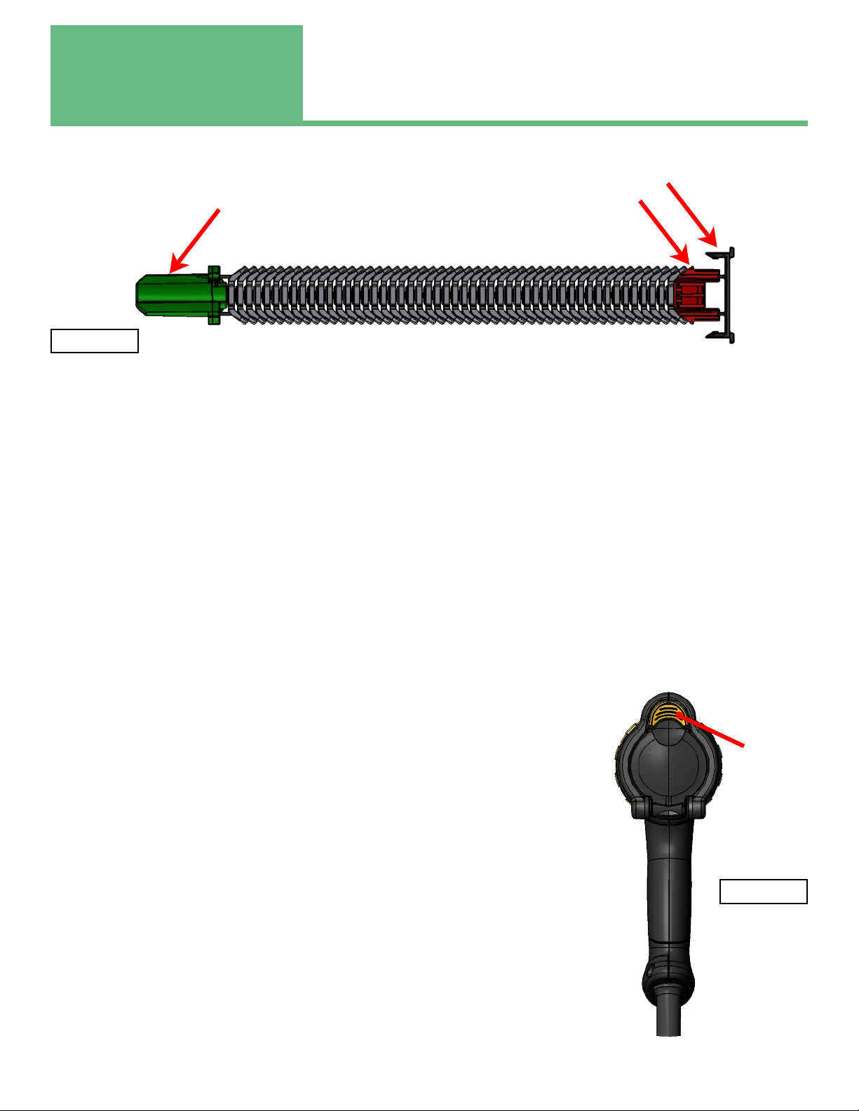
QUIKLINX MAGAZINE
The QuikLinx magazine and weld tool are highly engineered components designed to maximize welding efficiency. There are
a few things to know:
1. The magazine slides into the back of the tool and snaps into place. Once it is snapped into place the magazine cannot be
removed from the rear of the tool. The clip carrier should not be removed; it assists with proper feeding of the QuikLinx
clips.
2. The retention pin should only be removed once the magazine is installed in the weld tool.
3. It is recommended to always install a full magazine of 50 clips. Partial magazines will not feed properly.
4. It is not recommended to “reload” the plastic magazine components. The red, black and green plastic components have
engineered features that perform special functions. After use, these features can degrade. The degraded function of
these pieces can lead to unsatisfactory performance of the QuikLinx system.
5. All the plastic components of the magazine assembly are recyclable. They all are stamped with a #5 for standard recycling
classification.
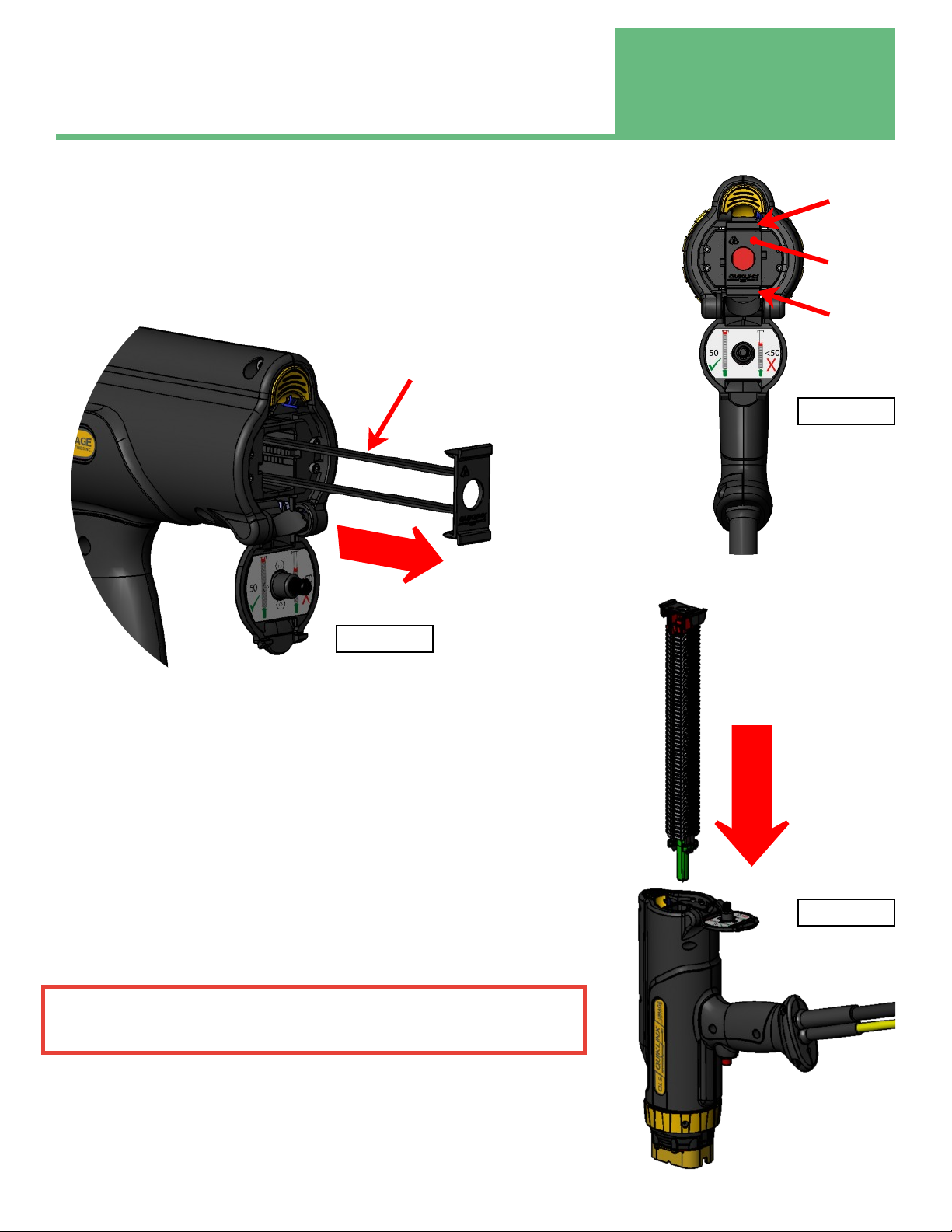
LOADING THE QUIKLINX CLIPS INTO THE WELD TOOL
Make sure the tool is completely empty of clips prior to loading a new magazine (See
trigger operation section to learn how to empty a magazine of clips). The clip advance
block is red in color. When you see the clip advance block in the grip pads you know the
magazine is empty. Do not try to remove the red clip advance block with your hands. It
is difficult to do. Rather, when you insert the next magazine, the red clip advance block
will be ejected.
Step 1 Open the rear door
Press the yellow button on the rear of the tool and the rear door will spring open.
Rear Door
Release Button
Retention Pin Clip Advance Block
Clip Carrier
50 QuikLinx Clips
Figure 3
Figure 4
Section 3 Normal Operation
12
Step 2 Remove Empty Clip Carrier (If one is present)
Using a your finger on the top finger hold and your thumb on the bottom thumb hold
(See Figure 5) pull rearward (See Figure 6) and the clip carrier will unsnap and come out
easily.
DO NOT REMOVE THE CLIP CARRIER WHEN THERE ARE CLIPS REMAINING IN
THE TOOL.
Discard the empty clip carrier into the recycling bin.
Step 3 Insert a New Magazine
Keeping the rear door open, slide the magazine into the gun with the green
retention pin leading (See Figure 7). The green retention pin will eject the red clip
advance block from the last magazine. Discard the ejected red clip advance block
into the recycling bin.
Notice the orientation of the clip carrier as shown in Figure 6. There is no top or
bottom orientation. Either orientation is correct.
The clip carrier will snap in place. It may need a push with your thumb to snap
the clip carrier in place. DO NOT FORCE the magazine in place. If the magazine
will not snap into place see trouble shooting guide.
ONCE A MAGAZINE IS FULLY INSERTED IT CANNOT BE REMOVED. IT
LOCKS INSIDE THE TOOL. CLIPS CAN ONLY BE EMPTIED FROM THE
FRONT.
Step 4 Close the Rear Door
Close the rear door. It will snap in place. The tool will not function without the
rear door closed.
Slide New Magazine
Into tool
Empty QuikLinx
Clip Carrier
Finger Hold
Thumb Hold
Figure 5
Draw Straight Out
Empty Clip Carrier
Figure 7
Figure 6
Normal Operation
Section 3
13
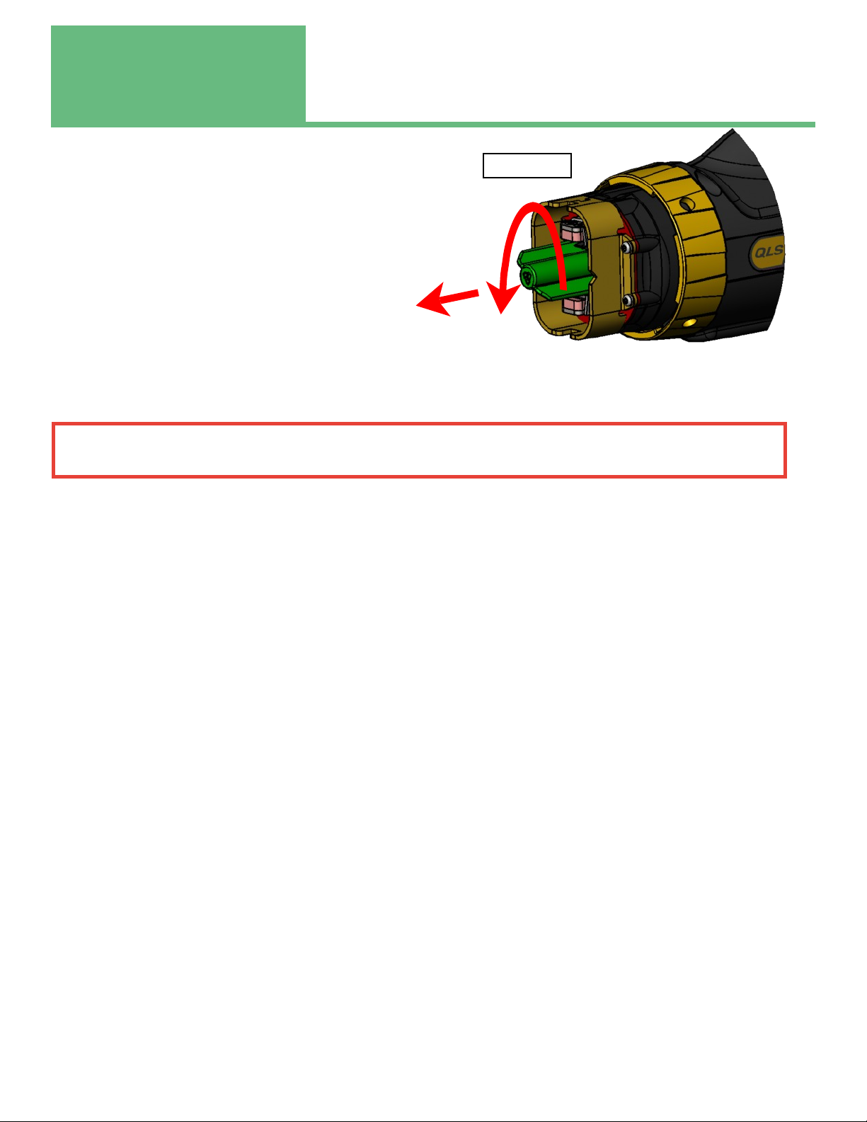
Step 5 Remove the Green Retention Pin
Using your thumb and index finger, rotate the green retention pin
counter clockwise 90° (¼ turn). When the retention
pin has released it will make a snapping noise.
Pull the pin straight out. Discard the loose green
retention pin into the recycling bin.
Step 6 Turn on the Power Source
This will energize the entire system. After the power
source microprocessor has completed its start up
routine, the tool will automatically go through a “find
home” routine.
BEST PRACTICE: WHENEVER CHANGING FROM ONE TOOL TO ANOTHER TOOL, THE NEW TOOL
SHOULD BE RE-HOMED BY CYCLING POWER OR USING TRIGGER FUNCTION 3
Step 7 Load a clip for welding
See Trigger Function 2 Below
TRIGGER FUNCTIONS
There are 4 different trigger functions that this tool can perform.
Trigger Function 1: Lift Check
When the clip in the tool is not in contact with a grounded work piece, pressing and releasing the trigger will perform
a “Lift Check”. This allows the operator to know there is good communication with the power source. It also lets the
operator know the tool itself is functioning. During a “Lift Check” the tool will draw the clip back into the tool the
thickness of the clip. This simulates the motion the tool performs during a weld.
Trigger Function 2: Load a clip
When a new magazine is installed, there is no clip loaded in the grip fingers to be welded. The tool must be told to
“Load a Clip”. This is done by rapidly pressing the trigger twice in succession. Both presses should be completed
within ½ second. This is also useful if the clip in the fingers gets removed or knocked out of position. Whenever the
grip fingers are empty and a clip is needed, this is the go to function. A magazine can be emptied by repeated use of
this function.
Trigger Function 3: Re-Home the Tool
Rarely, the tool may lose track of home position. The tool needs to run through it’s homing routine. The homing
routine is the same function that happens when the power source is turned on. It is not always convenient to go back
to the power source and cycle power. The homing function can be done by pressing and holding the trigger for 5
seconds. The tool will automatically re-home. The tool will perform a lift check first, than after 5 seconds will do the
re-home function. There is no harm if the re-home function is done accidentally.
Trigger Function 4: Weld
When the tool is in contact with a grounded work piece and the spark shield face is flat on the surface then a single
trigger pull will initiate a weld. It is not necessary to hold the trigger during a weld, but it also does not cause any
problems to hold the trigger during a weld.
1) Rotate green retention pin Counter-Clockwise. Hear it “snap”
2) Pull the green retention pin straight out.
1
2
Figure 8

Section 3 Normal Operation
14
CLIP POSITION
After a clip load (quick double trigger press) the clip should be in the position shown in
Figure 9. If the clip is not in this position perform a re-home function (press trigger and
hold for 5 seconds). If the clip still is not in this position then contact the factory for
assistance.
WELD SETTINGS
Recommended Power Source Current & Time Settings
The recommended values for welding QuikLinx clips depend on the type of QuikLinx clip and the welding process being used.
Types of Clips
There are 2 types of clips that can be used with the QuikLinx tool:
Unfluxed 10306MAG Used for Short Cycle Welding or Gas Arc
Fluxed 10450MAG Used for more robust applications and harder to weld materials like HSLA or AR400
Note: These are recommended settings. Your specific circumstance and application may require different settings. Always
test and validate your weld before using in a production scenario.
Refer to the power source manual to set up and adjust the power source.
Checking Weld Quality
The weld quality can best be checked with a torque test. Image offers a torque check attachment (Part number 10441)for a
standard torque wrench. We recommend a maximum torque check value of 30 ftlbs. Beyond 30 ftlbs the wings of the
QuikLinx clip begin to distort.
Type Part Number Process Current (A) Time (Sec)
Un-Fluxed 10306MAG Short Cycle 700 0.200
Un-Fluxed 10306MAG Gas Arc 700 0.400
Fluxed 10450MAG Standard 450 0.400
Figure 9
Type Part Number Process Passing
Torque
Un-Fluxed 10306MAG Short Cycle 20 ftlbs
Un-Fluxed 10306MAG Gas Arc 25 ftlbs
Fluxed 10450MAG Standard 30 ftlbs

Normal Operation
Section 3
15
WELDING
Proper Gun Position
It is important to have the tool in the proper position for welding. The brass
spark shield MUST be in full contact with the work surface (Figure 10).
It is tempting to lean on one edge of the spark shield, particularly if the
operator is in a hurry (Figures 11 & 12). Take the time to ensure the
tool is properly positioned.
Initiate a Weld
Once in position, press the trigger button and the system will weld one clip.
DO NOT PULL OFF THE WELD TOO QUICKLY
After the arcing has stopped. Wait for 1 second before removing the tool from
the clip. Then pull the tool straight off of the clip. Resist the temptation to
rock the tool off of the clip. The grip pad life will be extended by removing
the tool straight off of the QuikLinx clip.
If you to pull off of the clip too quickly, the clip may not have had time
to bond to the work piece. It is likely to remain in the grip pads. The
best way to eject this clip is to feed another clip..
Once the tool has been removed from the welded clip, the tool will
automatically load another clip without any user interaction.
Built in Safety Check
The QuikLinx Autofeed tool has a built in check to ensure proper weld
position. If the tool is not pressed all the way down on the work, the
unit is designed not to weld. If you press the trigger and the unit does
not weld you may not have had the spark shield fully flat against the
work piece.
End of a Magazine
When the last clip in the stack of the magazine has been welded, the
tool will try to load a clip as usual. However, it will grab the red clip
advance block and put it in the “weld” position.
If the operator tries to weld the plastic clip advance block, the tool will
perform a “lift check” function and no welding will occur. No harm is
done.
The red clip advance block is difficult
to remove with human fingers.
Warning: The spark shield and grip
fingers may be HOT. Let the next
magazine push the red clip advance
VERY IMPORTANT
Brass spark shield MUST be
In full contact with the work
surface
Work Piece
Figure 10
MUST BE FLAT
TOP VIEW
MUST BE FLAT
SIDE VIEW
Figure 12
Figure 11
WARNING

Special Welding Techniques
Section 4
16
PROCESS DISCUSSIONS
This section is provided to give a brief overview of different stud welding processes. If you have additional questions, consult
your distributor for additional information or refer to the “Recommended Practices for Stud Welding”; ANSI/AWS C5.4,
American Welding Society, Inc.
General Process Discussion
The arc stud welding process involves the same basic principles as any other arc welding process. Application of the process
consists of two steps:
(1) Weld heat is developed with an arc between the stud (electrode) and the plate (work).
(2) The two pieces are brought into contact when the proper temperature is reached.
The time required to complete a weld varies with the cross-sectional area of the stud. For example, weld time typically would
be about 0.13 seconds for a 10 gage (0.134 in.[2.6 mm]) stud, and 0.92 seconds for a 7/8 in. (22 mm) diameter stud.
There are 4 basic Arc Stud Welding Processes
1. Standard Drawn Arc Stud Welding (DASW). This Process uses a flux load embedded into the weld end and a
sacrificial ceramic ferrule for shielding. Because of the autofeed feature, QuikLinx foregoes the ceramic ferrule.
2. Gas Arc Stud Welding (GASW). This process uses no flux load and no ceramic ferrule. It does rely on shielding gas to
protect the weld zone.
3. Short Cycle Stud Welding (SCSW). This process uses no flux, ferrule or shielding gas. Welds are achieved with high
currents and short weld times. Welds of this nature are subject to porosity.
4. Gas Arc Short Cycle Stud Welding (GASCSW). This weld uses high current and short weld times similar to SCSW, but
adds shielding gas to prevent porosity.
Standard Drawn Arc Stud Welding (DASW) with flux load
The stud is loaded into the stud weld tool or weld head chucking mechanism, the ferrule (also known as an arc shield) is placed
into the ferrule grip over the end of the stud, and the weld tool is properly positioned for welding, The trigger is then pressed,
starting the automatic welding cycle. Note: The QuikLinx clip is unique in that it does not require a ceramic ferrule.
A lift mechanism within the body of the weld tool is energized. This lifts the stud off the work and, at the same time, creates
an arc. The end of the stud and part of the work piece are melted by the arc. When the preset arc period is completed, the
welding current is automatically shut off and the lift mechanism is de-energized by the control unit. The weld tool plunges
the stud into the molten pool on the work to complete the weld. The weld tool is then lifted from the stud and the ferrule is
broken off.
The Drawn Arc Stud Welding (DASW) process is the most robust stud welding process. It can weld effectively and reliably
under a broad range of conditions. The flux/ferrule combination also provides the greatest weld penetration into the base
material. Of the available arc processes, this should be the designer’s first choice. The other processes are typically selected
as a trade off for some factor.
Gas Arc Stud Welding (GASW) (uses shielding gas)
This process is similar to the DASW with a few exceptions. The stud is loaded into the chuck. There is a spark
shield used for gas delivery in place of the ferrule grip and the ferrule. The weld tool is properly positioned. The trigger is
pulled and gas pre-flow begins. When the pre-flow time has elapsed the automatic weld cycle begins and follows the same

Section 2
Section 4 Special Welding Techniques
1717
sequence as DASW. At the end of the weld cycle gas post-flow begins. After the gas post-flow concludes the entire weld
cycle is complete and the weld tool can be removed.
While the actual weld arc times are similar to DASW there is typically gas pre-flow and post-flow times which add to the
overall time per weld.
Since no ferrule is required handling and cleanup are reduced. The absence of a ferrule has pros and cons. On the plus side it
can reduce the cost of the studs. It also lends itself to automated processes since the handling operations are reduced. On
the minus side there is less fillet control. This can create difficulties when welding in any direction other than down handed.
Additionally, shielding gas does not typically offer as deep of penetration as flux.
Short cycle Stud Welding (SCSW)
This process is similar to DASW except no flux load or ferrule is used. Instead of a ferrule grip and ferrule a spark shield is
used. The process sequence is the same as for DASW. Because there is no flux or shielding gas this process typi- cally
exhibits porosity. The fundamental difference between this process and DASW is that high currents and short weld
times are used. The short weld time minimizes the effect of the porosity.
This is the least expensive process in that no ferrule or gas is utilized. This process also uses the shortest weld times. Short
weld times are used to minimizes the porosity from the unshielded atmosphere. Because of the porosity inherent in this
process it is generally not a recommended process. Factors such as thin sheet metal, insignificant strength requirements,
significant cost constraints, and very high installation speed requirements may over ride weld quality and this process may be
chosen.
Gas Arc Short Cycle Stud Welding (GASCSW)
This process combines GASW and SCSW. This uses the short cycle process, but adds shielding gas to eliminate the effects of
porosity. By reducing the weld time versus GASW there is better fillet control. However, weld current require- ments are
increased and can require a larger power supply. The reduced weld time also reduces weld penetration. This
can be a plus for arc welding onto thinner gauge sheet metal. Because shielding gas is used, the installed cost is greater than
SCSW, but porosity is eliminated.
SPECIAL TECHNIQUE DISCUSSION
Low-Carbon Steel
Low-carbon (mild) steels can be stud welded with no major metallurgical problems. The upper carbon limit for steel to be arc
stud welded without preheat is 0.30 percent. If work sections are relatively thin for the stud diameters being welded, the
carbon limit may be somewhat higher because of the decreased cooling effect of the work. If the section to which the
stud is to be welded is relatively thick, stud welding of steel with more than 0.30 percent carbon using normal techniques
and without preheat must be evaluated. The most important factor regarding work section thickness is that the material
must be heavy enough to permit welding the studs without melt-through.
Medium Carbon Steel
If medium carbon steels are to be stud welded, it is imperative that preheat be used to prevent cracking in the heat- af- fected
zones. In some instances, a combination of preheating and post-heating after welding is recommended. In the case of tough
alloy steels, either preheating or post-heating may be used to obtain satisfactory results. In cases where the welded assemblies
are to be heat treated for hardening after the welding operation, the preheating or post-heating operation may be eliminated
if the parts are handled in a manner that prevents damage to the studs.

Special Welding Techniques
Section 4
18
Low Alloy Steel
Generally, the high-strength, low alloy steels are satisfactorily stud welded when their carbon content is 0.15 percent or lower.
This range fits the analyses of low alloy steels used in welding and forming operations. If the carbon content exceeds 0.15
percent, it may be necessary to preheat the work to a low preheat temperature to obtain desired toughness in the weld
area.
When the hardness of the heat-affected zones and the stud fillet does not exceed 30 Rockwell C, studs can be expected to
perform well under almost any type of severe service. Although good results have been obtained with hardness ranges up to
35 Rockwell C, it is best to avoid extremely high working stresses and fatigue loading. In special cases where microstructures
are important, the weld should be evaluated and qualified for the specific application considered. Since alloy steels vary in
toughness and ductility at high hardness levels, weld hardness should not be used as the sole criterion for weld evaluation.
Heat Treated Structural Steel
Many structural steels used in shipbuilding and in other construction are heat-treated at the mill. Heat-treated steels re- quire
that attention be given to the metallurgical characteristics of the heat-affected zone. Some of these steels are sufficient- ly
hardenable that the heat-affected zones will be martensitic. This structure will be quite sensitive to underbead cracking, and it
will have insufficient ductility to carry impact loads. Therefore, for maximum toughness in these steels, a preheat of 700°F
(370°C) is recommended. Consideration of the application and end use of the stud will further influence the welding
procedures to be followed.
Stainless Steel
Most classes of stainless steel may be stud welded. The exceptions are the free-machining grades. However, only the
austenitic stainless steels (300 grades) are recommended for general application. The other types are subject to air harden-
ing, and they tend to be brittle in the weld area unless annealed after welding. The weldable stainless steel grades include
American Iron and Steel Institute (AISI) Types 302, 304, 305, 308, 309, 310, 316, 321, 347, 410 and 430. Types 302, 304 and
316 are most commonly used for stud welding.
Stainless steel studs may be welded to stainless steel or to mild steel as the application may require. The welding setup used
is the same as that recommended for low-carbon steel except for an increase of approximately 10 percent in power require-
ment. Where stainless steel studs are to be welded to mild steel, it is essential that the carbon content of the base metal not
exceed 0.20 percent. When welding stainless steel studs to mild steel with 0.20 to 0.28 percent carbon, or to low-carbon
hardenable steels, Type 308, 309, or 310 studs are recommended. Because of the composition of the weld metal when
chromium-nickel alloy studs are welded to mild steel, the weld zone may be quite hard. The hardness will depend on the
carbon content in the base metal. It is possible to overcome this by using studs with high-alloy content such as Type 309 or
310. It is also suggested when welding stainless steel studs to mild steel that a fully annealed stainless steel stud be used.
Plated Material
Stud Welding can be successfully accomplished onto plated base materials. Care must be taken when arc welding onto plated
materials as harmful gasses can be generated. Typical plating on base materials is zinc on galvanized sheet. The rust
prohibitive zinc is burned away in the weld zone and no longer provides rust protection at the weld zone. Even if stainless
steel fasteners are used there is potential for corrosion in the weld zone.
Frequently, corrosion resistance is desired on the fastener, yet the cost of stainless is prohibitive. Many manufacturers pro-
duce weld studs with various platings. Most common is a nickel plate, but other platings are available. As with plated base
materials, the plating is burned away in the weld zone. There is a potential for corrosion in the weld zone.

Section 2
Section 4 Special Welding Techniques
1919
Shielding Gas Selection for Steels
The choice of gas depends on two factors, weld penetration and appearance. Pure argon provides the best looking welds,
but has the least weld penetration. To increase penetration C02 is added to the mix. C02 percentages range from 10% to
25% depending on the desired level of penetration. Stainless steel will typically use a mix of 82% Argon and 18% C02.
Other mixes are used to achieve different results.
Table of contents
Other Image Industries Power Tools manuals


