Image Industries GA User manual

ILM009A
June, 2006
Instruction for Usage and Maintenance for
GA and GL Model Gap Weld Tools
These INsTRUCTIONs aRe fOR expeRIeNCed OpeRaTORs. If you are not fully
familiar with the principles of operation and safe practices for arc welding equipment, we urge
you to read AWS SP - “Safe Practices” available from the American Welding Society.
DO NOT permit untrained persons to install, operate, or maintain this equipment. DO NOT
attempt to install or operate this equipment until you have read and fully understand these in-
structions. If you do not fully understand these instructions, contact your supplier for further in-
formation. Be sure to read the Safety Precautions before installing or operating this equipment.
BE SURE THIS INFORMATION REACHES THE OPERATOR. EXTRA COPIES ARE AVAILABLE THROUGH YOUR SUPPLIER.
Price $5.50 USA
Operation Manual
CAUTION
GA Model
with optional
Tripod Legs
GA Model with
Template Nozzle
GL Model

2
SECTION 1: Safety Precautions 3
SECTION 2: Installation & Set Up 8
SECTION 3: Normal Operation 15
SECTION 4: Trouble Shooting 17
SECTION 5: System Maintenance 19
SECTION 6: Parts List 20
Table of Contents
W A R R A N T Y
Image warrants that the goods sold will be free from defects in workmanship and material. This warranty is
expressly in lieu of other warranties, expressed or implied or for fitness for a particular purpose. The liability shall
arise only upon return of the defective goods at Buyer’s expense after notice to Image. The warranty shall be
limited to replacement with like goods or, at Image’s option, to refunding the purchase price. Image will not accept
receipt of equipment returned unless buyer has previously afforded Image’s personnel a reasonable opportunity
to inspect and repair said equipment. Image will warrant components for 1 year and labor for 180 days from date
of shipment. Image shall not be liable for any consequential damages including improper set up by customer.

3
Safety Precautions
Section 1
USERS RESPONSIBILITY
This equipment will perform in conformity with the description contained in this manual and accompanying labels and/or
inserts when installed, maintained and repaired in accordance with the instructions provided. This equipment must be checked
periodically. Defective equipment should not be used. Parts that are broken, missing, worn, distorted or contaminated
should be replaced immediately. Should such repair or replacement become necessary, the manufacturer recommends
that a telephone or written request for service advice be made to the Authorized Distributor from whom purchased.
This equipment or any of it’s parts should not be altered without the prior written approval of the manufacturer. The
user of this equipment shall have the sole responsibility for any malfunction which results from improper use, faulty main-
tenance, damage, improper repair or alteration by anyone other than the manufacturer or a service facility designated by
the manufacturer.
WARNING: These Safety Precautions are for your protection.
They summarize precautionary information from the references
listed in the Additional Safety Information section. Before
performing any installation or operating procedures, be sure to
read and follow the safety precautions listed below as well as all
other manuals, material safety data sheets, labels, etc. Failure to
observe Safety Precautions can result in injury or death.
This symbol appearing throughout this manual means
ATTENTION! BE ALERT!
Your safety is involved.
The following definitions apply to DANGER, WARNING, CAUTION
found throughout this manual.
Used to call attention to immediate haz-
ards which, if not avoided, will result in
immediate, serious personal injury or loss
of life.
Used to call attention to potential hazards
which could result in personal injury or lost
of life.
Used to call attention to hazards which
could result in minor personal injury.
CAUTION
WARNING
DANGER
4
Safety Precautions
Section 1
ARC RAYS CAN BURN EYES AND SKIN -
The arc, like the sun, emits ultraviolet and infrared (visible and
in-visible) and other radiation and can injure skin and eyes.
Sparks and hot metal can fly off the weld. Training in the proper
use of the processes and equipment is essential to prevent ac-
cidents. Therefore:
1) Always wear safety glasses with side shields in any work area, even if wearing a
welding helmet, face shields and goggles are also required.
2) Always use a face shield fitted with the correct shade of filter to protect your
face and eyes when welding or watching (See ANSI Z49.1 and Z87.1 listed
in Safety Standards). Cover sparks and rays of the arc when operating or
observing operations.
3) Use protective non-flammable screens or barriers to protect others from
flash and glare. Warn bystanders not to watch the arc and not to expose
themselves to the rays of the electric-arc or hot metal.
3) Wear flameproof gauntlet type gloves, heavy long-sleeve shirt, cuffless trou-
sers, high topped shoes, and a welding helmet or cap for hair protection, to
protect against arc rays and hot sparks or hot metal. A flameproof apron may
also be desirable as protection against radiated heat and sparks.
4) Hot sparks or metal can lodge in rolled up sleeves, trousers cuffs or pockets.
Sleeves and collars should be kept buttoned, and open pockets eliminated
from the front of clothing.
6) Use goggles over safety glasses when chipping slag or grinding. Chipped slag
may be hot and can fly far. Bystanders should also wear goggles over safety
glasses.
ELECTRICAL SHOCK -
Contact with live electrical parts and ground can cause severe
injury or death. The electrode (the weld stud and chuck) and
work circuit (ground) are electrically live whenever the output
is on. The input power circuit and the machine internal circuits
are also live whenever power is on. Improperly installed or
improperly grounded equipment is a hazard.
1) Disconnect input power before installing or servicing this equipment. Lock-
out/tagout input power according to OSHA 29 CFR 1910.147 (see Safety
Standards).
2) Do not touch live electrical parts. Do not touch the electrode (stud) if you
are in contact with the work, ground, or another electrode from a different
machine.
3) Be sure the power source frame (chassis) is connected to the ground system
of the input power.
4) When making input connections, attach proper grounding conductors first and
then double-check connections.
5) Always verify the supply ground - check and be sure that input power cord
ground wire is properly connected to ground terminal in disconnect box or
that cord plug is connected to a properly grounded receptacle outlet.
6) Refer to ANSI/ASC Standard Z49.1 (listed on page 6) for specific grounding
recommendations. Do not mistake the work lead for a ground cable.
7) Clamp work cable with good metal-to-metal contact (spring and/or magnetic
clamps are not recommended) to work piece as near the weld as practical.
8) DO NOT use welding current in damp areas, if movement is confined, or if
there is danger of falling.
9) Properly install and ground this equipment according to this Owner’s Manual
and national, state and local codes.
10) Connect the work cable to the work piece. A poor or missing connection can
expose you or others to a fatal shock.
11) Keep everything dry, including clothing, work area, cables, torch/electrode
holder and power source.
12) Wear dry, hole-free insulated gloves & body protection before turning on
power.
13) Insulate yourself from work and ground using dry insulating mats or covers big
enough to prevent any physical contact with the work or ground.
14) Don’t stand directly on metal or the earth while working in tight quarters or a
damp area; stand on dry boards or an insulating platform and wear rubber-
soled shoes.
15) Turn off all equipment when not in use.
16) Use well-maintained equipment. Frequently inspect input power cord and out-
put weld cables for damage or bare wiring. Replace worn or damaged cables
immediately; bare wiring can kill. Repair or replace damaged parts at once.
Maintain this unit according to the manual.
17) Do not use worn, damage, undersized or poorly spliced cables.
18) Do not drape cables over your body.
19) If earth grounding of the work piece is required, use a separate cable.
20) Wear a safety harness if working above floor level.
21) Keep all panels and covers securely in place.
22) Insulate work clamp when not connected to work piece to prevent contact
with any metal object.
23) Don’t connect multiple electrodes or work cables to a single weld output
terminal.
SIGNIFICANT DC VOLTAGE exists after removal of the input power on
inverters. Turn off inverter, disconnect input power, and discharge input
capacitors according to instructions in Maintenance Section before touching
any parts.
ELECTRIC AND MAGNETIC FIELDS -
Electric and Magnetic Fields may be dangerous. Electric current
flowing through any conductor causes localized Electric and
Magnetic Fields (EMF). Welding and cutting current creates EMF
around welding cables and welding machines.
Therefore:
1) Welders having pacemakers should consult their physician before welding.
EMF may interfere with some pacemakers.
2) Exposure to EMF may have other health effects which are unknown.
3) Welders should use the following procedures to minimize exposure to EMF:
A) Route the electrode and work cables together. Secure them with tape
when possible.
B) Never coil the torch or work cable around your body.
C) Do not place your body between the torch and work cables. Route
cables on the same side of your body.
D) Connect the work cable to the work piece as close as possible to the
area being welded.
E) Keep welding power source and cables as far away from your body as
possible.
FLYING METAL CAN INJURE EYES -
1) Welding, chipping, wire brushing and grinding can cause
sparks and flying metal. As welds cool, they can throw
off slag.
2) Wear approved safety glasses with side shields even under
your welding helmet.
BUILD UP OF GAS CAN INJURE OR KILL -
1) Shut off shielding gas supply when not in use.
2) Always ventilate confined spaces or use approved air-
supplied respirator.
5
Safety Precautions
Section 1
CYLINDER HANDLING -
Shielding gas cylinders contain gas under high pressure. If dam-
aged or mishandled a cylinder can explode and violently release
gas. Sudden rupture of cylinder, valve, or relief device can injure
or kill. Since gas cylinders are normally part of the welding
process, be sure to treat them carefully. Therefore:
1) Protect compressed gas cylinders from excessive heat, mechanical shocks,
slag, open flames, sparks and arcs.
2) Keep cylinders away from any welding or other electrical circuits
3) Never drape a welding tool over a gas cylinder
4) Never allow a welding electrode (weld stud) to touch any cylinder
1) Use the proper gas for the process and use the proper pressure reducing
regulator, hoses and fittings designed to operate from the specific
compressed gas cylinder. Do not use adaptors. Maintain hoses and fittings
and other associated parts in good condition.
2) Always secure cylinders in an upright position by chain or strap to suitable
hand trucks, undercarriages, benches, walls, post, or racks. Never secure
cylinders to work tables or fixtures where they may become part of an
electrical circuit.
3) When not in use, keep cylinder valves closed. Have valve protection cap
in place if regulator is not connected. Secure and move cylinders by using
suitable hand trucks. Avoid rough handling of cylinders.
4) Locate cylinders away from heat, sparks, and flames. Never strike an arc or
weld on a cylinder; it will explode.
6) Turn face away from valve outlet when opening cylinder valve.
5) For additional information, refer to CGA Standard P-1, “Precautions for
Safe Handling of Compressed Gases in Cylinders”, which is available from
Compressed Gas Association, 1235 Jefferson Davis Highway, Arlington, VA
22202
WELDING CAN CAUSE FIRES AND EXPLOSIONS -
Welding on closed containers, such as tanks, drums or pipes, can
cause them to blow up. Sparks can fly off from the welding arc.
The flying sparks, hot work piece, and hot equipment can cause
fires and burns. Accidental contact of electrode to metal objects
can cause sparks, explosion, overheating or fire. Check and be
sure the area is safe before doing any welding. Therefore:
1) Protect yourself and others from flying sparks and hot metal.
2) Do not weld where flying sparks can strike flammable material.
3) Remove all combustible materials a minimum of 35ft away from the welding
arc or cover the materials with a protective nonflammable covering. Com-
bustible materials include wood, cloth, sawdust, liquid and gas fuels, solvents,
paints and coatings, paper, etc.
4) Hot sparks or hot metal can fall through cracks or crevices in floors or wall
openings and cause a hidden smoldering fire or fires on the floor below. Make
certain that such openings are protected from hot sparks and metal.
5) Do not weld, cut, or perform other hot work until the work piece has been
completely cleaned so that there are no substances on the work piece which
might produce flammable or toxic vapors.
6) Be aware that welding on a ceiling, floor, bulkhead or partition can cause fire
on the hidden side.
7) Do not weld on closed containers such as tanks, drums or pipes unless they
are properly prepared according to AWS F4.1.
8) Connect work cable to the work as close to the welding area as practical to
prevent welding current from traveling long, possibly unknown paths and caus-
ing electric shock and fire hazards.
9) Do not use welder to thaw frozen pipes.
10) Remove electrode (weld stud) from the stud weld tool when not in use.
11) Remove any combustibles, such as a butane lighter or matches from your
person before doing any welding.
12) Have appropriate fire extinguishing equipment handy for instant use, such as
a garden hose, water pail, sand bucket or portable fire extinguisher. Be sure
you are trained for proper use.
13) Do not use equipment beyond its ratings. For example, overloaded welding
cable can overheat and create a fire hazard.
14) After completing operations, inspect the work area to make certain there are
no hot sparks or hot metal which could cause a later fire. Use fire watchers
when necessary.
15) For additional information, refer to NFPA Standard 51B, “Fire Prevention
in Use of Cutting and Welding Processes,” available from the National Fire
Protection Association, Batterymarch Park, Quincy, MA 02269
FUMES AND GASES -
Welding produces fumes and gases. Breathing these fumes and
gases can be hazardous to your health, particularly in confined
spaces. Do not breathe fumes and gases. Shielding gases can
cause asphyxiation. Therefore:
1) Keep your head out of the fumes. Do not breathe the fumes.
2) If inside, ventilate the area and/or use exhaust at the arc to remove welding
fumes and gases.
3) If ventilation is poor, use an approved air-supplied respirator.
4) Read the Material Safety Data Sheets (MSDS) and the manufacturer’s
instructions for metals, consumables, coatings, cleaners and degreasers.
5) Work in a confined space only if it is well ventilated, or while wearing an
air-supplied respirator. Always have a trained watch-person nearby. Welding
fumes and gases can displace air and lower the oxygen level causing injury or
death. Be sure the breathing air is safe.
6) Don’t weld in locations near degreasing, cleaning or spraying operations. The
heat & rays of an arc can react with vapors to form highly toxic & irritating
gases.
7) Don’t weld on coated metals, such as galvanized, lead or cadmium plated
steel, unless the coating is removed from the weld area, the area is well
ventilated, and if necessary, while wearing an air-supplied respirator. The
coatings and any metals containing these elements can give off toxic fumes if
welded.
8) Do not weld, cut, or gouge on materials such as galvanized steel, stainless
steel, copper, zinc, lead, beryllium or cadmium unless positive mechanical
ventilation is provided. Do not breathe fumes from these materials.
9) If your develop momentary eye, nose, or throat irritation while operating, this
is an indication that ventilation is not adequate. Stop work and take necessary
steps to improve ventilation in the work areas. Do not continue to operate if
physical discomfort persists.
10) Refer to ANSI/ASC Standard Z49.1 for specific ventilation recommendations.
NOISE CAN DAMAGE HEARING -
Noise from some processes or equipment can damage hearing.
1) Wear approved ear protection if noise level is high
FIRE OR EXPLOSION HAZARD -
1) Do not install or place unit on, over, or near combustible
surfaces.
2) Do not install unit near flammables.
3) Do not overload electrical wiring - be sure power supply
system is properly sized, rated and protected to handle the
unit.

6
Safety Precautions
Section 1
EQUIPMENT MAINTENANCE -
Faulty or improperly maintained equipment can cause injury or
death. Therefore:
1) Always have qualified personnel perform the installation,
troubleshooting, and maintenance work. Do not perform
any electrical work unless you are qualified to do the work.
2) Before performing any work inside a power source, disconnect the power
source from the incoming electrical power using the disconnect switch at the
fuse box before working on the equipment.
3) Maintain cables, grounding wire, connections, power cord, and power supply
in safe working order. Do not operate any equipment in faulty condition.
4) Do not abuse any equipment or accessories. Keep equipment away from:
- heat sources such as furnaces
- wet conditions such as water puddles and inclement weather
- oil or grease
- corrosive atmospheres.
5) Keep all safety devices and cabinet covers in position and in good repair.
6) Use equipment only for its intended purpose. Do not modify it in any
manner.
FALLING UNITS CAN CAUSE INJURY -
1) Use lifting eye to lift unit only, NOT running gear, gas
cylinders or any other accessories.
2) Use equipment of adequate capacity to lift and support unit.
3) If using lift forks to move unit, be sure forks are long enough
to extend beyond opposite side of the unit.
OVERUSE CAN CAUSE OVERHEATING -
1) Allow cooling period; follow rated duty cycle.
2) Reduce current or reduce duty cycle before starting to weld
again.
3) Do not block or filter airflow to unit
STATIC (ESD) CAN DAMAGE PC BOARDS -
1) Put on grounded wrist strap BEFORE handling boards or
parts.
2) Use proper static-proof bags and boxes to store, move or
ship PC boards.
MOVING PARTS CAN CAUSE INJURY -
1) Keep hands, hair, loose clothing and tools away from moving
parts.
2) Keep away from pinch points such as drive rolls.
WELDING WIRE CAN CAUSE INJURY -
1) Do not press weld tool trigger until instructed to do so.
2) Do not point weld tool toward any part of the body, other
people or any metal when threading welding wire.
MOVING PARTS CAN CAUSE INJURY -
1) Keep hands, hair loose clothing and tools away from moving
parts such as fans.
2) Keep all doors, panels, covers and guards closed and
securely in place.
3) Always disconnect electrical power prior to service to
prevent the fan from starting unexpectedly.
H.F. RADIATION CAN CAUSE INTERFERENCE -
1) High-Frequency (H.F.) can interfere with radio navigation,
safety services, computers and communications equipment.
2) Have only qualified persons familiar with electronic
equipment perform this installation.
3) The user is responsible for having a qualified electrician
promptly correct any interference problem resulting from the
installation.
4) If notified by the FCC about interference, stop using the equipment at once.
5) Have the installation regularly checked and maintained.
6) Keep high-frequency source doors and panels tightly shut, keep spark gaps at
correct setting, and use grounding and shielding to minimize the possibility of
interference.
ARC WELDING CAN CAUSE INTERFERENCE -
1) Electromagnetic energy can interfere with sensitive electronic
equipment such as computers and computer-driven
equipment such as robots.
2) Be sure all equipment in the welding area is electro-
magnetically compatible.
3) To reduce possible interference, keep weld cables as short as
possible, close together, and down low, such as on the floor.
4) Locate welding operation 100 meters from any sensitive electronic equipment.
5) Be sure this welding machine is installed and grounded according to this
manual.
6) If interference still occurs, the user must take extra measures such as moving
the welding machine, using shielded cables, using line filters, or shielding the
work area.
EMF Information
Considerations about welding and the effects of low frequency Electric and Magnetic
Fields (EMF):
Welding current, as it flows through welding cables, will cause electromagnetic
fields. There has been and still is some concern about such fields. However, after
examining more than 500 studies spanning 17 years of research, a special blue
ribbon committee of the National Research Council concluded that: “The body of
evidence, in the committee’s judgement, has not demonstrated that exposure to
power-frequency electric and magnetic fields is a human-health hazard.” However,
studies are still going forth and evidence continues to be examined. Until the final
conclusions of the research are reached, you may wish to minimize your exposure
to electromagnetic fields when welding or cutting. See section on EMF on page 2.
HOT PARTS CAN CAUSE SEVERE BURNS -
1) Do not touch hot parts with bare hands.
2) Allow cooling period before working on welding tool (gun
or torch).

7
Safety Precautions
Section 1
ADDITIONAL SAFETY INFORMATION -
For more information on safe practices for electric arc welding refer to the following publications:
American Welding Society
550 N.W. LeJuene Road, Miami, FL 33126, (phone 305-443-9353, website: www. aws.org)
1) ANSI/ASC Z49.1 - Safety in Welding, Cutting and Allied Processes
2) AWS CH5 - Recommended Practices for Stud Welding
3) AWS D1.1 - Structural Welding
2) AWS C5.1 - Recommended Practices for Plasma Arc Welding
3) AWS C5.6 - Recommended Practices for Gas Metal Arc Welding
4) AWS SP - Safe Practices - Reprint, Welding Handbook.
5) ANSI/AWS F4.1, Recommended Safe Practices for Welding and Cutting of Containers and Piping.
National Fire Protection Association
P.O. Box 9101, 1 Battery March Park, Quincy, MA 02269-9101 (phone 617-770-3000, website: www.nfpa.org and sparky.org)
1) NFPA Standard 70 - National Electrical Code
2) NFPA Standard 51B - Standard for Fire Prevention During Welding, Cutting and Other Hot Work
Compressed Gas Association
1735 Jefferson Davis Highway, Suite 1004; Arlington, VA 22202-4102 (phone 703-412-0900, website: www.cganet.com)
1) CGA Pamphlet P-1 - Safe Handling of Compressed Gas Cylinders
Canadian Standards Association
Standards Sales, 178 Rexdale Blvd, Rexdale, Ontario, Canada M9W 1R3 (phone 800-463-6727 in Toronto 416-747-4044, website: www.csa-international.org)
1) CSA Standard W117.2 - Code for Safety in Welding and Cutting
American National Standards Institute
11 West 42nd Street, New York, NY 10036-8002 (phone 212-642-4900, website: www.ansi.org)
1) ANSI Standard Z87.1 - Practice for Occupational and Educational Eye and Face Protection
U.S. Government Printing Office
Superintendent of Documents, P.O. Box 371954, Pittsburgh, PA 15250 (phone 312-353-2220, website: www.osha.gov)
1) Title 29, Code of Federal Regulations (CFR), Part 1910, Subpart Q, & Part 1926, Subpart J - Occupational Safety and Health Standards for General Industry
With any power source, it may or may not contain a battery which may contain hazardous materials. Please follow
local battery disposal procedures when changing batteries or disposing of the power supply.
California Proposition 65 Warnings
Welding or cutting equipment produces fumes or gases which contain chemicals known to the State of Cali-
fornia to cause birth defects and , in some cases, cancer. (California Health & Safety Code Section 25249.5 et
seq.)
Battery posts, terminals and related accessories contain lead and lead compounds, chemicals known to the
State of California to cause cancer and birth defects or other reproductive harm. Wash hands after handling.
For Gasoline Engines:
Engine exhaust contains chemicals known to the State of California to cause cancer, birth defects, or other
reproductive harm.
For Diesel Engines:
Diesel engine exhaust and some of its constituents are known to the State of California to cause cancer, birth
defects, and other reproductive harm.

8
Installation & Set Up
Section 2
COLLET ADJUSTMENTS
Collet with Adjustable Depth Stop
It is necessary to properly set up the collet for the size fastener you are welding. First select the proper diameter collet for
the size fastener you are welding (see chart below). Secondly, the adjustable depth stop must be set to accommodate the
length of the fastener. The stop should be set so that 3mm or .125” of the stud sticks past the end of the collet and the stud
is firmly against the adjustable depth stop. Note: Some collets may have a jam nut. Adjust depth stop to required height
and firmly tighten jam nut while holding the depth stop position with a screwdriver (not shown).
Collet with Collet Protector (Gauge Series Collets)
Gauge series collets include a collet protector which prevents contact between the end of the collet and the weld stud. This
feature prevents arcing between the fastener and the collet. Also, gauge series collets contain no depth stop which allows
long length fasteners to be used with the weld tool.
Select the appropriate sized collet and protector for the fastener to be
welded. The fastener should be inserted so the head of the fastener is
pressed firmly against the collet protector. The collet protector should
be periodically inspected to insure that no foreign material is embedded
in the collet protector.
* The IMAGE Collet Part Numbers in the table to the left having asterisks indicate the gauge
series collets designed for long fasteners. Gauge series Collets have no provision for a depth
stop and include a collet protector.
This end into Spindle
Adjustable Depth Stop Fastener
Collet
.125” or 3mm
Collet Protector
Weld Pin
This end into spindle
Fastener Size IMAGE Collet
Part #
14 GA CLI08P*
#4 CLI10
12 GA CLI10P*
#6 CLI13
10 GA CLI13P*
#8 CLI16
#10 CLI19
1/4 CLI25
M3 CLIM3
M4 CLIM4
M5 CLIM5
M6 CLIM6

9
Installation & Set Up
Section 2
Collet Installation and Removal
To install a collet, make sure the collet nut is loose and that the col-
let slides freely into the spindle. Slide the collet into the spindle until it
bottoms out at the back of the spindle. Do not force collet into spindle.
Tighten collet nut finger tight with supplied collet nut wrench (part
#GRM12). Do not use a bar or other leverage to over-tighten the collet
nut. This will damage the spindle.
Note: It is not necessary to remove the collet nut from the spindle to
install a collet.
To remove a collet, loosen the collet nut with the supplied collet nut
wrench (part #GRM12). Grasp the collet and pull collet away from the
weld tool body.
Note: It is not necessary to remove the collet nut from the spindle to
remove a collet.
Collet
Wrench
Collet Nut
Collet

10
Installation & Set Up
Section 2
FOOT & LEG SET UP (GL Model Only)
The GL model weld tool comes supplied with a foot and spark shield. The
foot is installed on the ends of the legs. Alignment of the foot is important.
The collet should be located in the center of the spark shield. To install the
foot, unscrew the socket head screws from the ends of the legs. Place the
washers on the socket head screws and place the screws through the
counter bored holes in the foot. Reattach the screws to the legs.
When installing the legs on the foot be sure and align the flats of the
legs to the outside. This is necessary to facilitate installation of the tool.
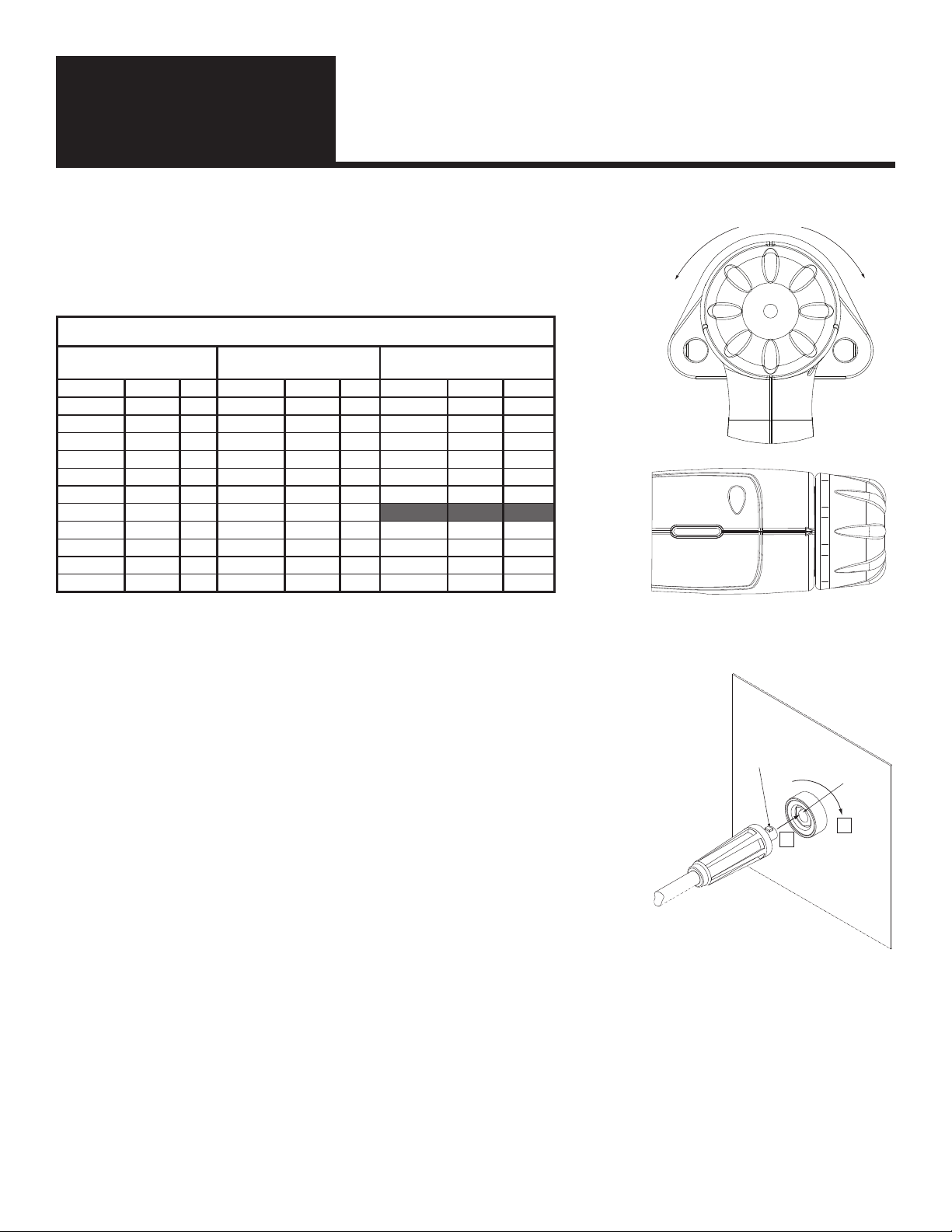
To remove or install the spark shield, find the set screw(s) that retain(s) the spark shield
in the foot. Loosen the set screw and push the spark shield into the foot. The spark
shield is sometimes a tight fit so press it firmly into the foot so it seats against the back
stop. Do not over tighten the set screws.
Insert the legs into the face plate. Line up the flat on the leg with the face plate set screw. (Tighten
the set screws in the side of the legs.) The set screw will bite into the flat region and hold the leg
securely. If the set screw bites into the round portion of the leg it will cause damage to the leg so it
won’t insert into the weld tool face plate anymore.
Note: If the round part of the leg has a burr, remove the burr with a metal file so that it can slide easily in the face
plate. If the leg becomes bent, replace the leg.
Spark Shield
Washer
Foot
Leg
Set Screw
Face Plate
Leg
Retention
Set Screw
Spark
Shield Collet
Foot
Leg Screw

11
Installation & Set Up
Section 2
PLUNGE ADJUSTMENT
Plunge, or the amount of weld stud sticking past the end of the spark shield or template nozzle, should be set to 1mm
(.040) which is approximately the thickness of the flange of a typical Capacitor Discharge Weld Stud.
Note: The collet depth stop should be set properly prior to adjusting the
plunge. See section on adjusting collets.
Adjusting Plunge for GL Model
To adjust plunge, loosen the leg retention set screw on both sides of the face plate. Slide the leg and foot assembly forward
or backward until 1mm of the weld stud protrudes past the end of the spark shield.
Retighten the leg retention set screws.
Adjusting Plunge for GA Model
To adjust plunge, pull out the plunge adjustment knob away from the tool body and rotate to the right, or follow the
direction indicated on the decal, to decrease plunge. Rotate the plunge adjustment knob to the left, or follow the direction
indicated on the decal, to increase plunge. Rotate knob until 1mm of the weld stud protrudes past the end of the spark
shield or tripod legs. The knob will automatically lock into position once released. The same process is used for the
tripod foot.
Leg Arrangement of Tripod foot for GA Model
The GA Model offers an optional tripod foot that comes with a Tripod support and three Tripod Legs.
The Tripod Bracket allows the user to move/customize the leg position to accommodate their specific
work piece.
The legs can be loosened with a 5mm or adjustable wrench at the provided wrench flats and relocated
as required.
Note: The Tripod Bracket and legs are a self tensioning design. Only
tighten the Tripod Leg until it comes in contact with the Tripod Bracket.
Do Not Over Tighten.
Plunge Depth (typically .040” or 1mm)
Collet
Collet Nut
Face Plate
Spark Shield Foot Leg Retention Set Screw
Plunge Depth
typically .040” or 1mm
Plunge Adjustment Knob
6 Tripod Leg
Mounting Positions
5mm
Wrench Flat
Tripod Legs
Tripod
Bracket
12
Installation & Set Up
Section 2
ADJUSTING WELD PARAMETERS
The gap setting can be changed by adjusting the rear knob. The default setting is 4.
Turning the knob to the lower numbers (blue region on the decal) makes the welds
colder. Turning the knob to the higher numbers (red region on the decal) makes the
welds hotter. See table for recommended settings.
CONNECTING TO A POWER SUPPLY
Hooking the weld tool to a stud welding power supply is straight forward.
There are three steps:
Weld Tool
1. Connect the weld cable.
2. Connect the control cable.
Ground Cable
3. Connect the weld ground.
Weld Cable
The weld tool cable inserts in the following way. Line up the rectangular protrusion on
the weld cable with the notch on the top side of the panel receptacle (typically the weld
cable goes into the negative (- weld tool) receptacle). Push the weld cable connector
straight in as far as it will go [Step 1]. Hand turn clockwise to tighten [Step 2]. See
Figure 2.
Weld Ground
The ground cable is connected in the same fashion as the welding tool weld cable. The ground cable typically is inserted into
the positive (+ ground) receptacle for straight polarity welding.
Key
Key way
1
2
Figure 2
H
o
t
t
e
r
(
+
)
C
o
l
d
e
r
(
-
)
6 5 4
Gap Weld Tool Recommended Voltage Settings
Mild Steel Stainless Steel Aluminum
Stud Size Voltage Gap Stud Size Voltage Gap Stud Size Voltage Gap
12 ga 60 4 12 ga 60 4 12 ga 75 3
10 ga 75 4 10 ga 75 4 10 ga 90 2 2/3
#4 60 4 #4 60 4 #4 75 3
#6 75 4 #6 75 4 #6 90 2 2/3
#8 85 4 #8 85 4 #8 110 2 2/3
#10 100 4 #10 100 4 #10 125 2 1/3
1/4 150 5 1/4 150 5
3MM 75 4 3MM 75 4 3MM 90 2 2/3
4MM 85 4 4MM 85 4 4MM 110 2 2/3
5MM 100 4 5MM 100 4 5MM 125 2 1/3
6MM 150 5 6MM 150 5 6MM N/A N/A
13
Installation & Set Up
Section 2
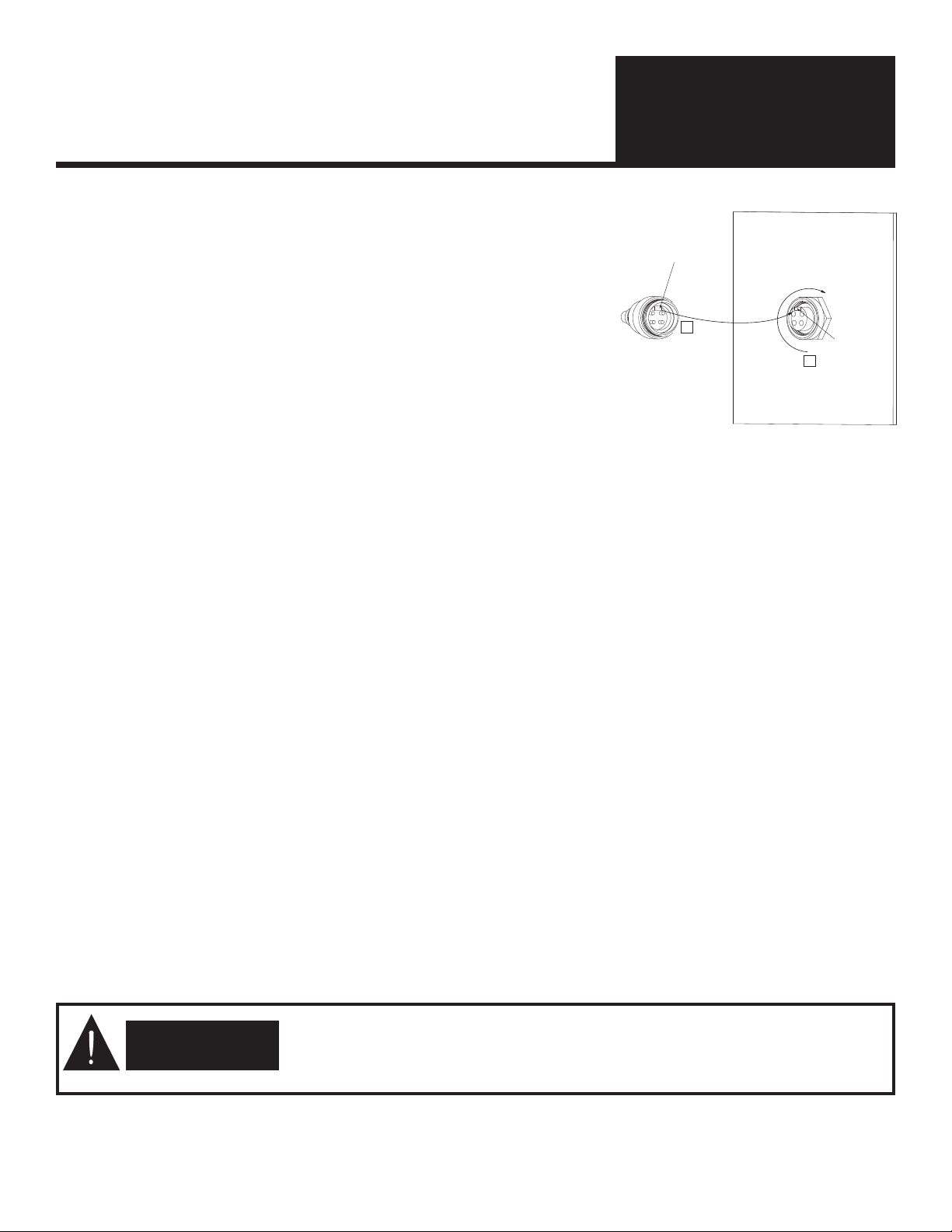
Control Cable
There is a key in the end of the control cable connector. Align the key in the
cable connector with the key way in the front panel control cable receptacle.
Push the cable connector into the front panel receptacle [Step 1]. When the two
are seated turn the screw ring on the cable connector clockwise [Step 2]. This
will lock the two together. See Figure 3. The screw ring does not need to be
overly tight.
There are 4 basic types of connections. Connecting the control cable will vary
with the style of the control cable that is on your new gun.
1. Screw Style which mates to Image Industries Equipment.
2. R&S (4 pins Nelson, Erico, KSM)
Align the bump on the shell of the connector with the relief in the receptacle. Push the cable connector firmly into
the receptacle.
To remove, twist the outer shell of the cable connector counter clockwise. While holding the shell in a counter
clockwise position pull the connector straight out.
3. Hubble (2 pins Nelson)
To connect a 2 pin style connector, line up the wide tab with the wide slot. Push forward on the connector when
the connector housing contacts the receptacle turn the connector body 1/8 turn clockwise.
Cable Connections
Straight Polarity: In straight polarity the weld tool is connected to the negative (-) electrode. The ground lead is connected
to the positive (+) receptacle (often ground). This cable arrangement is the preferred arrangement for welding ferrous met-
als with either the gap or contact processes.
Reverse Polarity: Reverse polarity reverses the weld tool and ground connections. The weld tool connects to the positive
(+) receptacle and the ground cable connects to the negative (-) electrode. This cable arrangement is preferred for welding
materials such as aluminum, brass or galvanized with either the gap or contact processes.
Layout: The cables must be laid out straight. If the cables are coiled the amount of energy available for weld will be reduced.
This will result in poor quality welds. This is true for both the weld tool weld cable and the ground cable when using either
the gap or contact processes.
Note: For gap weld tools there should not be more than 10 feet of weld cable. Longer weld cables will impede the weld
energy flow and possibly result in poor welds.
WARNING
WARNING: To prevent accidental activation of the weld tool, always disconnect
the weld cable from the power supply before making any weld tool adjustments
or performing any service on the weld tool.
Key
Key way
1
2
Figure 3

14
Installation & Set Up
Section 2
GA MODEL CONTROL CONNECTOR and WELD CONNECTOR
Part Numbers for the Complete Tool
Part Numbers for the Components.
Weld Tool with Foot Control Connector Part Numbers
Weld Connector
Screw R&S Hubble
Cam lock GRDAC-09 GRD2C-09 GRD6C-09
Dinse GRDAZ-09 GRD2Z-09 GRD6Z-09
Control Connector Weld Connector
Screw R&S Hubble Cannon Cam Lock dINSE
Connector Only CSS4AM CRS4AM CHB2AM CCN6AM CCL1/0AMB CDN04AMB
Cable Assembly CC2BA-10 CC1B2-10 CC1B6-10 CC1B4-10 CW0VC-09 CW0VZ-09
Weld Tool with Template Nozzle Control Connector Part Numbers
Weld Connector
Screw R&S Hubble
Cam lock GRFAC-09 GRF2C-09 GRF6C-09
Dinse GRFAZ-09 GRF2Z-09 GRF6Z-09
Camlock
weld connector
#CCL1/0AMB
Dinse
weld connector
#CDN04AMB
Screw
Connector
R & S
Connector
Hubble
Connector
Cannon
Connector
15
Normal Operation
Section 3
STUD GUN TOOL FUNCTIONS
The stud weld tool automates the stud welding process. It performs several key functions:
1. It holds the stud.
2. It holds the spark shield, tripod foot, or template nozzle.
3. It sets the rate at which the fastener contacts the work surface.
STUD WELDING STEPS
Before you begin to weld anytime it is important to review the set up. By making sure that the weld tool is set up properly,
you will have the best welding results. A majority (about 95%) of all stud welding problems are due to improper weld tool
set up or improper power settings.
1. Place the stud to be welded into the weld.
2. Position the end of the stud onto a location where the stud is to be welded.
3. Press the weld tool downward so the spark shield or template nozzle are sitting on the base metal.
4. Ensure the stud is perpendicular to the base metal.
5. Pull the trigger to begin the weld sequence.
6. Hold the weld tool still during the welding process.
7. Remove the weld tool from the welded stud. Be sure and pull the weld tool straight off of the welded stud
to prevent damage to the collet.
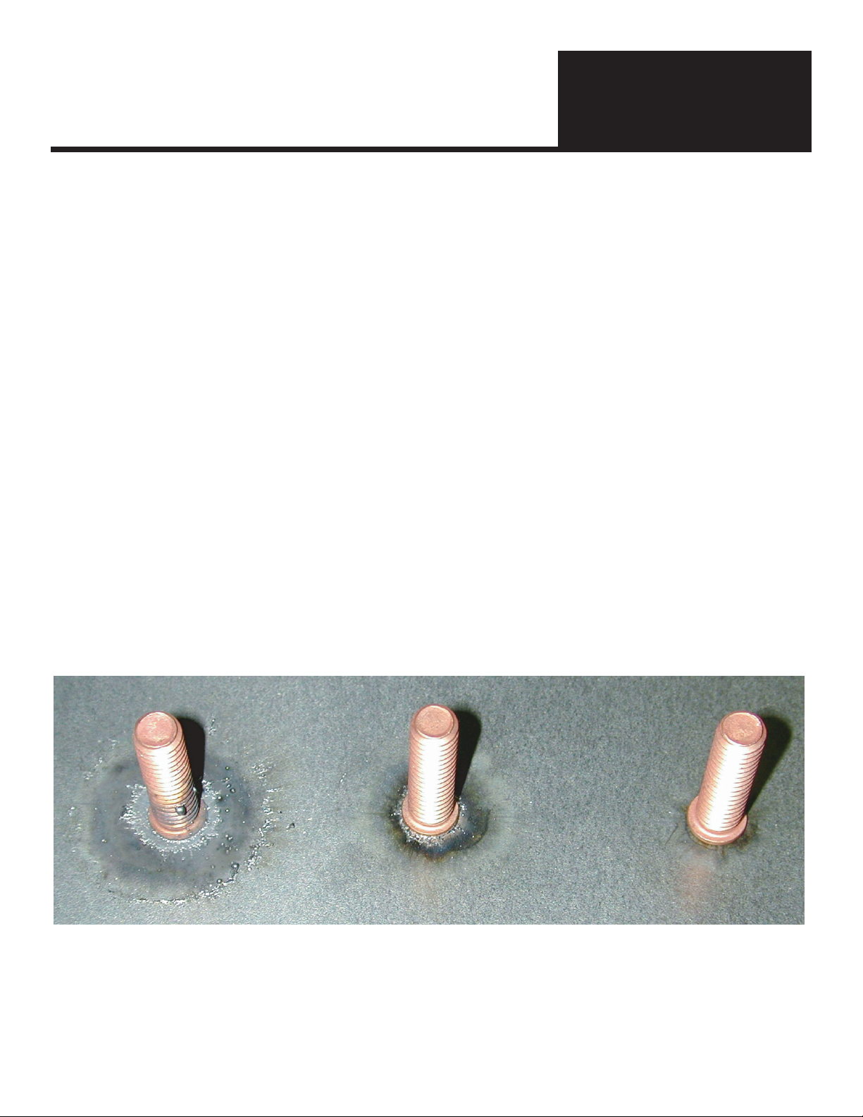
Weld Quality Visual Inspection
Weld Examples and Solutions
Reduce Weld Voltage
Or increase initial gap
turn rear knob to
lower numbers.
No Adjustments Required
Too Hot
Excessive weld flash
and weld spatter.
This weld may break.
Correct
Normal weld flash.
No significant weld spatter.
This will be a good, strong weld.
Too Cold
No excessive weld flash
and weld spatter.
This weld may break.
Increase Weld Voltage
Or reduce initial gap
turn rear knob to
higher numbers.

16
Normal Operation
Section 3
GAP CAPACITOR DISCHARGE PROCESS
Note: The tip design/dimensions are very important. The ignition tip controls the arc length and weld duration. If the
ignition tip is too short there will not be enough weld time to ensure an adequate weld. This means that you can not weld
into a center punch mark. A center punch mark effectively reduces the tip length and will adversely affect welding results.
Stud starts in contact with
the work piece. The stud is
positioned over the target.
Upon contact with the base
metal, the ignition tip
vaporizes and an arc is
formed. This arc melts
the bottom of the stud
and top of the base metal.
Complete
fusion
At the end of travel, the
power source is completely
discharged and the stud
has formed a complete bond
with the base material.
Initial gap
The weld tool
continues to drive
the stud toward
the base metal
The tool trigger is pulled and
the tool’s mechanisms lift
the weld stud off of the
work creating the initial gap
After the gap distance is
achieved, the weld tool
mechanism accelerates
toward the weld site.

17
Trouble Shooting
Section 4
TROUBLE SHOOTING
Additional Gap Welding Problems
HOT WELD characterized by excessive weld splatter: Increase Gap Distance - This speeds up the weld time (faster drop time)
and the faster drop time extinguishes the arc sooner. Decrease Voltage - Reducing the voltage reduces overall energy into
the weld.
COLD WELD characterized by almost no weld splatter and apparent undercut on the weld base. When the stud is broken off,
there will only be a small area of melted metal which will be dull and gray in color: Decrease Gap Distance - The shorter distance
reduces the drop speed which allows for a longer arc or weld time. Increase Voltage - Increasing the voltage increases
overall energy into the weld.
COLD PLUNGE characterized by a shiny surface after the stud is broken off and may not have much weld splatter: Increase Gap
Distance - This increases drop speed and gets stud into molten pool faster. Cold Plunge occurs when the molten metal
cools before the stud and the base material are bonded together. A Cold Plunge typically occurs with aluminum and other
non-ferrous alloys but can also occur with steel.
PROBLEM: COLD WELD
Possible cause of Cold Welds Possible Solutions
Tip on stud is crushed due to excessive pressure. Some-
times (especially with aluminum studs) an operator can ap-
ply repeated pressure to the stud tip and crush or shorten
the tip. The shortened tip reduces arc length/time and
does not properly melt the stud and or base material.
Make sure plunge is properly adjusted. Refer to Plunge
Adjustment in Section 2 of the Operation Manual.
Coiled weld or ground cables. This reduces weld current
delivered to the stud. The coiled cables act like a large
inductor and inhibit the flow of energy.
Make sure weld and ground cables are not coiled during the
stud welding process.
Improperly set power supply controls. Refer to the Operation Manual for the equipment for cor-
rect setup of power supply.
Improperly formed tip on stud due to manufacturing pro-
cess.
Replace stud with one that is correctly formed.
Changes in alloys being welded. Changes in alloys can usually be compensated for by chang-
ing the settings on the power supply.
Equipment failure. Refer to the Operation Manual for the power supply for this
information.
Improperly set plunge setting. Decrease or increase plunge. See Plunge Adjustment in Sec-
tion 2 of the Operation Manual.
Varying gauges of sheet metal. Changes in sheet metal can usually be compensated for by
changing the settings on the power supply.
Springs inside weld tool have fatigued and don’t apply the
same pressure.
Return weld tool to Image Industries for service.
Dirt inside weld tool prevents smooth operation and hangs
up or slows gun operation.
Return weld tool to Image Industries for service.

18
Trouble Shooting
Section 4
Additional Gap Welding Problems (cont.)
ARC BLOW characterized by weld spatter of fillet on only one side of the stud (looks like molten metal was “blown” out from only the
one side of the stud). This problem will often cause incomplete fillet formation on one side of the stud. This incomplete cross
sectional welding may lead to weld failure.
There are two causes for this:
Possible Cause - Molten metal runs away from the ground. Incomplete or insufficient grounding can cause this
problem.
Possible Solution - Double Ground. The addition of another ground on opposite sides of the weld area will reduce
this problem. The object will be to always weld between the grounds. If you need assistance contact your Image
Industries Representative.
Possible Cause - Welding near the edge (1/4 inch or less) of a piece of metal will potentially cause this phenomena.
Unusual electrical current patterns are set up near the edges of metals and this can effect the flow of metal.
Possible Solution - Place another piece of sheet metal of the same type and thickness next to the edge you are
welding. This will “fool” the electrical currents and they will act like you are welding in the middle of the sheet metal.
SLIDING STUDS characterized by the stud sliding during the welding process. It will look like a metal skid mark and be shiny. This
problem occurs when the stud finishes a weld in a different location than where it was initially placed on the sheet of metal.
There are three causes for this:
Possible Cause - The operator is pushing down with a great deal of pressure and/or is holding the gun at a slight angle.
Possible Solution - Check the plunge setting. Use a minimum plunge that provides acceptable welding results. This will
reduce the amount of pressure the operator needs to use to weld the stud. Also check the foot or nose piece to ensure
that it is flat and provides a stable surface for welding.
Possible Cause - The chuck is worn. This will allow the stud to be at a slight angle and can allow the set up to slide
during the weld process.
Possible Solution - Check the chuck for wear and replace if needed.
Possible Cause - The weld tool internal components are excessively worn.
Possible Solution - Contact you Image Industries Representative for possible repair or replacement.
CENTER PUNCH MARKS are not recommended in CD Welding. Contact you Image Industries Representative for ideas on
creating a location mark if it is required. When the tip of the CD stud is located in a center punch mark, the overall length
of that tip is effectively reduced. This reduction in length will dramatically effect weld time and therefore weld quality. If
the depth of the mark can be consistently controlled and kept to 0.005” the weld parameters may be able to be adjusted
to compensate for the difference in weld time. However, experience has shown that this kind of control over the depth of
center punch marks is not practical.

19
System Maintenance
Section 5
WHEN IS MAINTENANCE REQUIRED?
Maintenance requirements will vary with environment and usage. Dirty work areas or high volume stud welding will require
more frequent maintenance.
There are three prime reasons for maintenance:
1. Dirt. Dirt can enter the lifting mechanism and cause erratic plunge operations. Typically, cleaning is all that is
required.
2. Wear. Components do wear out over time. Typically, items such as the plastic bearings or cables wear out and
need to be replaced.
3. Improper Use. Components can arc out by inadvertently placing them against grounded materials during a weld
sequence.
Maintenance Steps
Because the weld tool components are in a sealed housing the recommended maintenance procedure for this weld tool is to
return it to your distributor or manufacturer for service.
WARNING
WARNING: To prevent accidental activation of the weld tool, always disconnect
the weld cable from the power supply before making any weld tool adjustments
or performing any service on the weld tool.
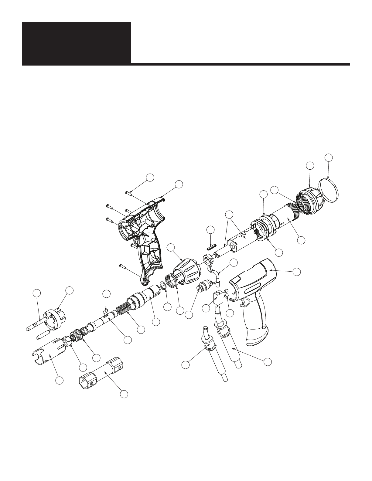
20
Parts List
Section 6
21
18
01
19
22
14
16
13
15
10
02
12
11
20
06
03
05
09
26
27
04
07
08
23
24
28
17
25
29
14
GA Model
With this weld tool you will either have a spark shield #23 or a tripod foot assembly #26 & #27. Both do not ship the the
tool. Different attachments can be purchased as options. For further information on control and weld connectors go back
to page 13 of this manual.
This manual suits for next models
1
Table of contents
Other Image Industries Power Tools manuals


