manuals.online logo
Brands
  1. Home
  2. •
  3. Brands
  4. •
  5. Image Sensing Systems
  6. •
  7. Radar
  8. •
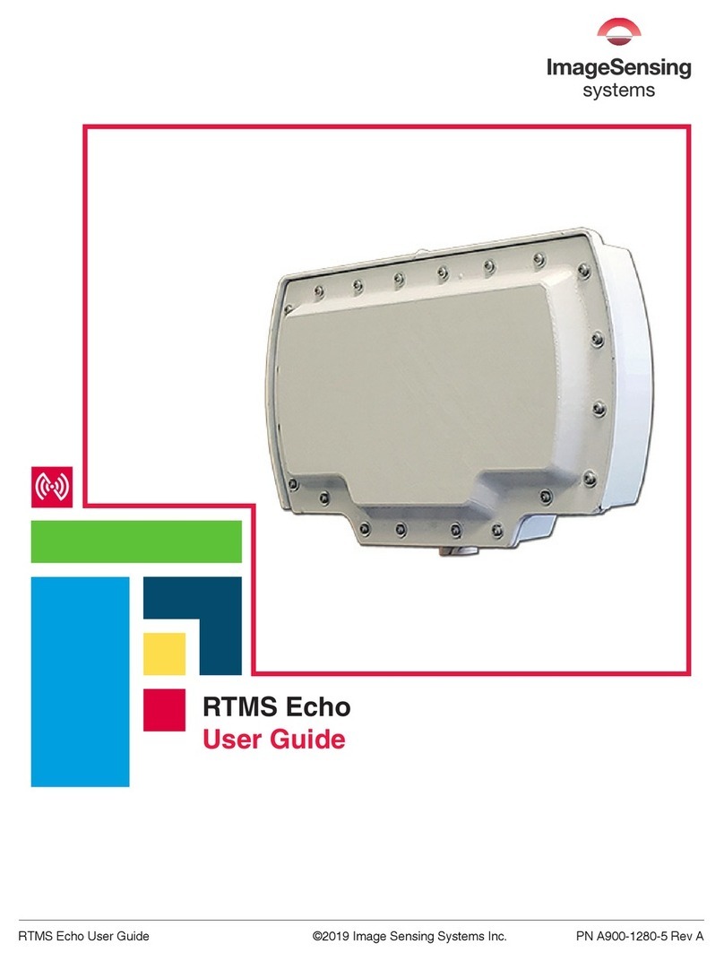
  9. Image Sensing Systems RTMS Echo User manual

Image Sensing Systems RTMS Echo User manual

RTMS Echo
Quick Start Guide
Mounting Height and Tilt Recommendations
Mount the RTMS Echo
NOTE: Always follow local wiring codes and local standards that apply
to the location in which the RTMS
Echo is being installed.
1. Attach the bracket to the roadside
pole (or another specied
location) using stainless steel
banding or bolts.
2. Secure the RTMS Echo to the
mounting bracket using the
washer, lock washer and nut.
Make sure that the cable
connector is on the bottom of
the unit when it is mounted.
3. Adjust the RTMS Echo to be
perpendicular to the travel
lanes and level with the road.
This is the roll and can be ne
tuned in section 5.
4. Tilt the RTMS Echo so that the sensor is aimed at the farthest
monitored zone. The tilt recommended in section 2 can be ne
tuned in section 5.
5. Hand tighten the nuts for the moment. Final tightening will be
done after the aiming process (section 5).
CAUTION: Make sure the mains are
turned off prior to connecting the wires.
6. Undo the protective cap on the
sensor’s connector.
7. Insert the RJ-45 connector
from the cable to the RJ-45
receptacle on the bottom of the
sensor.
8. Tighten the cable’s locking
collar by turning it a quarter
turn to the right.
9. Connect the other end of the
cable to 12-24VDC power and communications in the breakout
box according to the pinouts shown below. In addition, the silver
(non-colored) wire must be connected to Earth ground.
NOTE: Surge suppression is recommended and ltering may be
required (see the help system for details).
1
2
3
4
5
6
7
8
RJ-45
Green
White/Green
Orange
White/Orange
Blue
White/Blue
White/Brown
Brown
Rx-
Tx-
Rx+
Tx+
VIN+
VIN-
VIN-
VIN+
*Contact ISS Support for recommendations if outside these boundaries.
1
2
3
Closest Zone
(ft / m)
Recommended
Mounting Height
(ft / m)
Recommended
Tilt (degrees)
Maximum Recommended
Detection Distance*
(ft / m)
0 / 0 15 / 4.6 -27 100 / 30.5
5 / 1.5 15 - 22 / 4.6 - 6.7 -19 to -21 110 - 120 / 33.5 - 36.6
10 / 3.1 15 - 26 / 4.6 - 7.9 -16 to -20 120 - 140 / 36.6 - 42.7
15 / 4.6 15 - 28 / 4.6 - 8.5 -12 to -17 140 - 150 / 42.7 - 45.7
20 / 6.1 20 - 31 / 6.1 - 9.4 -12 to -16 160 - 170 / 48.8 - 51.8
25 / 7.6 23 - 34 / 7.0 - 10.4 -11 to -15 180 - 190 / 54.9 - 57.9
30 / 9.1 26 - 35 / 7.9 - 10.7 -11 to -13 200 / 61
35 / 10.7 28 - 35 / 8.5 - 10.7 -10 to -12 220 / 67.1
40 / 12.2 31 - 35 / 9.4 - 10.7 -10 to -11 235 / 71.6
45 / 13.7 33 - 35 / 10.1 - 10.7 -10 250 / 76.2
50 / 15.2 35 / 10.7 -10 250 / 76.2
55 / 16.8 35 / 10.7 -9 250 / 76.2
60 / 18.3 35 / 10.7 -8 250 / 76.2
• Stainless steel banding and/or stainless steel bolts used
to mount the sensor to a pole
• Junction boxes
• 12-24 VDC power supply, etc.
• Hand-held tally counter (recommended)
What’s in the Box
Scan to access Echo Online Help or by visiting
imagesensingsystems.com/echo-help
Other Required Equipment
• RTMS Echo
• Mounting bracket
• 50 ft (15.24 m) cable
+
RJ-45 receptacle on the
bottom of the sensor
Cable locking
collar
Cable RJ-45 connector
Mounting pole
Stainless steel band
Mounting bracket
Lock
Washer
Nut
Flat Washer
Echo Bracket
Mounting Bracket
7
8
Verify Vehicle Counts
1. Select the Calibrate tab.
2. Select the checkbox for each zone for which counts will be veried.
If more than one zone is selected, there should be one person with
a hand-held counter monitoring each zone.
3. Click Start and immediately begin counting vehicles as the cross
the RTMS Echo beam. Keep track of the count for each zone. When
at least 50 vehicles for each selected zone have been counted, click
Stop and enter the count for each zone in the Manual count column.
NOTE: If any of the percentages are over 5 percent (plus or
minus) corrections should be made before continuing (see the
Troubleshooting section in the User Guide or Online Help).
Congure Sensor Settings
1. Select the Settings tab.
2. In the Local area network section, click Change.
3. Enter the IP address, Subnet mask and Gateway to be used for the
sensor.
4. Click Save Changes.
5. In the Date and time section, click Change.
6. Select the time zone in which the sensor is installed.
7. Click Save changes.
8. Return to the main Settings page and make any additional changes
necessary.
Website: www.imagesensing.com
Email: service@imagesensing.com
PN A900-1280-1 Rev. E
© 2022 Image Sensing Systems, Inc. All Rights Reserved. No part of this document may be
reproduced or quoted without written permission from Image Sensing Systems, Inc. RTMS
and RTMS Echo are trademarks of Image Sensing Systems, Inc., registered in the United
States and other countries.
4
NOTE: If connecting through Wi-Fi, the wireless network for Echo is
“echo-xxxx” (xxxx is the device ID) and the password is “echo123456”.
1. Start a web browser on the device (i.e., computer, tablet, phone) used
to congure the Echo sensor.
2. In the URL eld enter:
• For Wi-Fi connections: 10.99.50.1
• For Ethernet connections: 192.168.0.10
3. Enter the login credentials. Defaults are: admin/rtmsecho
Connect to the Echo Web App
1. Select the Aim tab.
2. Rotate the sensor left or right to align the sensor perpendicular to
the road. This is the roll setting, which is normally 0; however, it
should be adjusted to the road angle if the road is not level.
3. Move the sensor forward and back to adjust the tilt according to
the table in Section 2.
4. Swivel the sensor left or right to
adjust the azimuth until it shows OK.
5. Once the roll and tilt are set, tighten
the nuts securing the sensor.
5
6
Aim the Sensor
Detect Zones
1. Select the Zones tab.
2. Click Auto Detect Zones.
There will be about one and a half minutes
of prep time before detection begins. As
objects are detected, the detection heat
map appears in the radar beam image.
Zones will appear when the system has
determined that the detected objects are
vehicles instead of stationary objects
(i.e., barriers, etc.). The full process
including prep time, takes approximately
8 and a half minutes; however, if all zones
in the detection area appear, you can
click All zones found to stop the process.
3. Click on a zone to display the zone
controls.
4. If desired, enter a name for the zone (25 characters maximum).
5. Verify that the selection under Trac direction is correct for the
direction of trac in the zone.
6. Repeat steps 3-5 for the
other zones.
7. When complete, click Save
changes.
Roll Tilt Azimuth
0° -11° OK

Other manuals for RTMS Echo

1

Other Image Sensing Systems Radar manuals

Image Sensing Systems RTMS Echo User manual

Image Sensing Systems

Image Sensing Systems RTMS Echo User manual

Popular Radar manuals by other brands

Sensors & Software Conquest Series manual

Sensors & Software

Sensors & Software Conquest Series manual

IDS GeoRadar RockSpot user guide

IDS GeoRadar

IDS GeoRadar RockSpot user guide

Blackbe;rry RADAR-M ITA100-1 installation guide

Blackbe;rry

Blackbe;rry RADAR-M ITA100-1 installation guide

Elan City EVOLIS VISION installation manual

Elan City

Elan City EVOLIS VISION installation manual

HIK VISION DS-TD10M-1 manual

HIK VISION

HIK VISION DS-TD10M-1 manual

Blackbe;rry RADAR-L installation guide

Blackbe;rry

Blackbe;rry RADAR-L installation guide

IDS GeoRadar STREAM DP user manual

IDS GeoRadar

IDS GeoRadar STREAM DP user manual

Endress+Hauser PROFIBUS PA Levelflex FMP50 Brief operating instructions

Endress+Hauser

Endress+Hauser PROFIBUS PA Levelflex FMP50 Brief operating instructions

ImpulseRadar PinpointR user manual

ImpulseRadar

ImpulseRadar PinpointR user manual

Endress+Hauser Levelflex FMP56 manual

Endress+Hauser

Endress+Hauser Levelflex FMP56 manual

nanoradar MR76 user manual

nanoradar

nanoradar MR76 user manual

Geolux RSS-2-300W user manual

Geolux

Geolux RSS-2-300W user manual

ATTOWAVE NEW RL360 manual

ATTOWAVE

ATTOWAVE NEW RL360 manual

Vega VEGAPULS 63 operating instructions

Vega

Vega VEGAPULS 63 operating instructions

Garmin Varia RTL515 Quick start manual

Garmin

Garmin Varia RTL515 Quick start manual

RHYTHM Hawkeye Installation and maintenance guide

RHYTHM

RHYTHM Hawkeye Installation and maintenance guide

Endress+Hauser Levelflex M FMP41C technical information

Endress+Hauser

Endress+Hauser Levelflex M FMP41C technical information

Endress+Hauser Micropilot M FMR250 operating instructions

Endress+Hauser

Endress+Hauser Micropilot M FMR250 operating instructions

manuals.online logo
manuals.online logoBrands
  • About & Mission
  • Contact us
  • Privacy Policy
  • Terms and Conditions

Copyright 2025 Manuals.Online. All Rights Reserved.