ImpulseRadar
PinpointR User Manual V1.0
Page 19 (32)
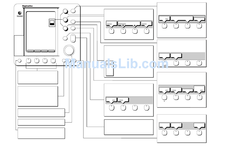
Figure 20 Controls during reference-line projects, forward survey, and profiles to the right of the first profile
Select the direction of the collection (forward/backward) and press the appropriate button to start the
profile. Note that the example in Figure 20 illustrates a forward move of the cart for all profiles in the
Reference Line project, requires a 180° turn at the end of each profile. The selected button will be
highlighted in green to indicate the selected direction and additional buttons (left/right) will become
available. These buttons are used for the placement of the reference marker, by indicating the position
of the start point in relation to the direction of travel, when crossing the reference-line.
Referring to, the first profile is collected by moving away from position 1. Upon reaching the reference-
line at point 2 a reference marker i placed in he daa b preing he righ arro bon The righ
button is selected because the next profile will be to the right of the first one. Make sure that the Cart
is stopped on top of the Reference line, arrows on the Cart hood must match the Reference line. The
profile continues to be collected until reaching point 3, at which the stop button is pressed.
The system is then moved to the start point of the second profile (point 4). Important to keep the
distance in-between the profiles as decided in figure17. Press the forward button to start the
measurement when the Cart is in position for the second profile. Upon reaching point 5, a reference
marker is again placed into the data. This time the left marker button is selected because the next
profile will be to the left of the present one.
After the last profile has been stopped just sweep from the
bottom of the screen on the standard Android way, tap on
the arrow pointing to the left and answer yes that this
Reference line project will be finished.
Figure 21, Close an RL-project
If data is correctly gathered, all profiles will be correctly aligned and orientated with the reference-
line and each other when opening the project in the CrossPoint® software.
Dual View (DV)
This project type is intended to aid in on-site interpretation, rather than in post-processing. It is
particularly useful for identifying features/objects that are relatively linear across a survey area, e.g.
foundation walls, tree roots or utility lines.
When collecting and viewing a single GPR profile, it is difficult to judge whether a reflector is a genuine
point of interest, or simply from random debris like a stone or piece of broken rock. Consequently, it
is useful to view one, or more, parallel profiles to assist in their interpretation. This is the basis for the
DV-project, which allows the current profile being collected to be viewed alongside the previous one,
thereby making it easier to see if reflectors line up in similar positions across them. For this to work,
the start position of each profile must be aligned with the stop position of the previous profile, as
shown below in Figure 22, below.


