nanoradar MR76 User manual

MR76 77GHz MMW Radar User Manual
MR76(v1.1)2020-3-10 Hunan Nanoradar Science and Technology Co., Ltd
1
MR76 77GHz MMW Radar
User Manual
湖南纳雷科技有限公司
Hunan Nanoradar Science and Technology Co.,Ltd.

MR76 77GHz MMW Radar User Manual
MR76(v1.1)2020-3-10 Hunan Nanoradar Science and Technology Co., Ltd
2
Disclaimers
Thanks to purchase this product. There is web pages about M R 7 6 radar sensor in our official website
(www.nanoradar.cn).You can find the latest product information and user manual on the pages. The
user manual is subject to change without notice.
Please read this manual carefully before using this product. Once used, it is deemed to have
recognized and accepted the content of this manual. Please strictly follow the manual to install and use
the product. Any improper use may cause damage or injury, and Nanoradar would not bear the
corresponding loss and liability.
Product copyright is retained by Nanoradar. Reproduction in any form shall not be done without
permission. The use of this product and manual shall not be pursued liability for the patent.

MR76 77GHz MMW Radar User Manual
MR76(v1.1)2020-3-10 Hunan Nanoradar Science and Technology Co., Ltd
3
Version history
Date
Version
Version description
2018-11-20
1.0
The 1st version of user manual on MR76
2020-3-10
1.1
Content add and revise

MR76 77GHz MMW Radar User Manual
MR76(v1.1)2020-3-10 Hunan Nanoradar Science and Technology Co., Ltd
4
CONTENT
1. Introduction..............................................................................................................................................................................5
1.1 Features....................................................................................................................................................................................5
1.2 Application examples.............................................................................................................................................................. 5
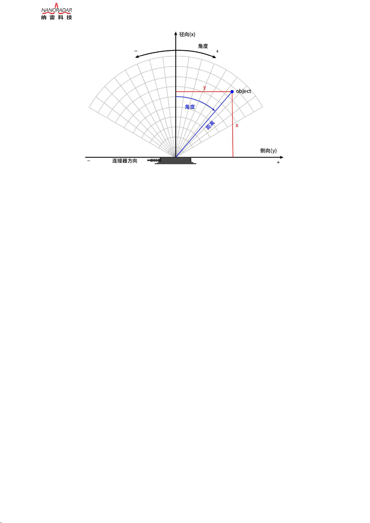
1.3 Radar principle.........................................................................................................................................................................6
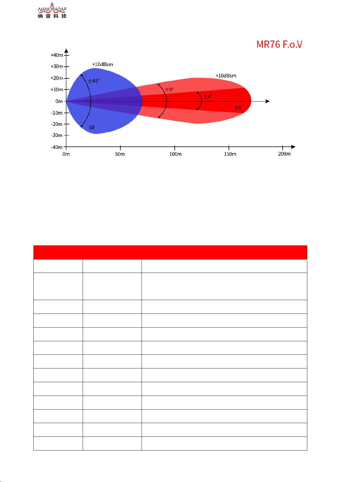
1.4 Radar FOV...............................................................................................................................................................................6
1.5 Technical Parameter................................................................................................................................................................ 7
2. Radar Connection....................................................................................................................................................................8
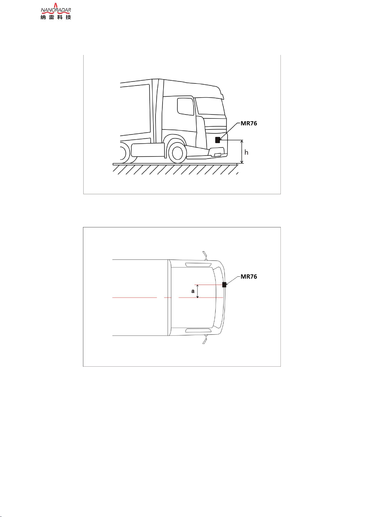
2.3.1 Mounting on Vehicle............................................................................................................................................................ 8
a. Thickness:............................................................................................................................................................................. 12
b. Spraying................................................................................................................................................................................... 12
c. Alignment................................................................................................................................................................................ 13
3. Electrical Conditions............................................................................................................................................................. 13
3.1 Cable Connection...................................................................................................................................................................13
3.2 CAN Interface........................................................................................................................................................................14
3.3 Test and Use.......................................................................................................................................................................... 14
4. Influence on Human Health..................................................................................................................................................16
5. Technical Parameter............................................................................................................................................................. 18
5.1 The Field of View (FoV)....................................................................................................................................................... 18
5.2 Cable Connection...................................................................................................................................................................19
6. Interfaces................................................................................................................................................................................ 20
6.1 CAN interface........................................................................................................................................................................20
6.2 Input Signals- Possible Dynamic Parameters........................................................................................................................ 21
7. Device Dimensions................................................................................................................................................................. 21
7.1 Dimensions......................................................................................................................................................................... 21
8. Notes on Safety and Risks..................................................................................................................................................... 21
8.1 Areas of responsibility........................................................................................................................................................... 22
9. Common faults and solutions............................................................................................................................................... 22

MR76 77GHz MMW Radar User Manual
MR76(v1.1)2020-3-10 Hunan Nanoradar Science and Technology Co., Ltd
5
1. Introduction
1.1 Features
The MR76 77GHz millimeter-wave radar provides short--range and medium-range dual-beam scanning
coverage for obstacles up to 170 meters.
It supports the following features:
A. Simultaneous detection of stationary and moving objects with relative speeds from -200km/h to
300km/h.
a) Information on the distance, velocity and angle of the object.
b) Classification of moving objects such as trucks, cars and pedestrians.
B. Dual scan provides detections in far range (up to 170 m) and extended field of view (FoV) in short
range up to 90°(-16dB)
C. Up to 64 tracking targets can be output via the CAN interface.
D. Support the integration of radar with other devices (such as cameras), which needs to be developed
by customers.
1.2 Application examples
The MR76 77GHz millimeter wave radar is suitable for applications such as special vehicles collision
avoidance and automotive forward collision avoidance. Other atypical applications are as follows:
A. Distance Monitoring/Warning: Distance monitoring with warning message if the distance to the
preceding object is too close.
B. Detection and tracking of people, vehicles, animals and equipment for collision avoidance in
industrial, construction, agricultural and mining applications.
C. Monitoring of automated manufacturing processes.
D. Condition monitoring of industrial plants.
E. Traffic monitoring for traffic management and safety applications with ability to distinguish objects
on different lanes
F. Monitoring and protection of vehicle and pedestrians on railway and passenger crossing
The High Sensitivity and High Resolution of the sensor ensures a safe detection of preceding vehicles
and also allows detection of targets in front of the preceding vehicle (by underbody reflections) even if
the line of sight is covered.

MR76 77GHz MMW Radar User Manual
MR76(v1.1)2020-3-10 Hunan Nanoradar Science and Technology Co., Ltd
6
1.3 Radar principle
The MR76 adopts the modulation method of FMCW (Frequency Modulated Continuous Wave). The
basic principle is that the transmitted wave is a high-frequency continuous wave, and its frequency
changes with the sawtooth wave rules by time. The changing rules of echo frequency received by the
FMCW is the same as the transmitted frequency, which is sawtooth wave rules. However, there is a time
difference. The target distance can be calculated by using thisl time difference.
Figure1 FMCW radar block diagram
Taking the sawtooth frequency modulated continuous wave as an example to briefly introduce the radar's
ranging/velocity measurement principle. As shown in Figure 1.1, blue is the transmitting signal
frequency, yellow is the receiving signal frequency, the sweep period is T, the sweep bandwidth is B, the
transmitted signal is transmitted through the target, and the echo signal has a delay, in the sawtooth
frequency change rules, the distance measurement can be performed on both the rising edge and the
falling edge.
1.4 Radar FOV
The MR76 77GHz millimeter wave radar is a mid-range radar. It can detect target distance, velocity and
position information by receiving radar reflections. Its FoV can reach ±45° in the close range and ±9° in
the medium range.

MR76 77GHz MMW Radar User Manual
MR76(v1.1)2020-3-10 Hunan Nanoradar Science and Technology Co., Ltd
7
Figure2 MR76 FoV
1.5 Technical Parameter
Table 1 MR76 Technical Parameter
Measuring performance to natural targets (non-reflector targets)
Modulation
FMCW
Distance Range
0.20~170m@±4°,0.20~120m@±9°(Mid range mode)
0.20~70m@±9°,0.20 - 40m@45° (short range mode)
Distance Resolution
spot target, none tracking
0.68m,ability to separate targets and objects 1.5…2 x resolution
Distance Accuracy
spot target, none tracking
±0.30m
FOV
±45°@-16dB
Angle Resolution
spot target, none tracking
±0.1°(middle mode), ±0.3°@0°、±1°@±45°(short mode)
Velocity Range
-200km/h...+300km/h (-leaving object,+approximation)
Velocity Resolution
spot target, none tracking
±1.23km/h
Velocity Accuracy
spot target, none tracking
±0.5km/h
Antenna Channels
2TX/4RX=8 channels
Cycle Time
60ms
Elevation beam
-6dB
14°
Azimuth beam
-6dB
18°

MR76 77GHz MMW Radar User Manual
MR76(v1.1)2020-3-10 Hunan Nanoradar Science and Technology Co., Ltd
8
2. Radar Connection
2.1 Interface Connection
MR76 support CAN bus Connection
2.2 Configuration and Startup/Shutdown/Failure Behavior
When the MR76 is connected to the bus or PC through the CAN protocol or serial port, please refer to
the "MR76 77GHz Millimeter Wave Radar Protocol Manual" for related protocols.
The MR76 radar does not support hot swapping. If the internal detection of the system finds an error, it
may cause the radar to malfunction or even cause the radar to restart.
3. Installation and Mounting Specification
3.1 Mounting on Vehicle
Radar Mounting
For front/rear detection and related applications, the MR76 is mounted at a height of 0.4 to 1.5 m from
the ground, and the radar antenna faces directly in front. The installation specification is shown in
MR76 Dual beams (mid-range and short-range) work simultaneously and can not be switched. The detected targets are output in
order of distance or RCS. By default, they are output by distance from near to far.
Operation Condition
Transmit frequency
ETSI&FCC
76…77GHz
Transmit capacity
average/peak EIRP
29.8dBm
Power
+8.0V~32VDC
Consumption
2.5W
Working Temp
-40℃…+85℃
Storage Temp
-40℃…+90℃
Protection class
IP67
Interface
Interface
1xCAN- High speed 500kbit/s
Cover
Dimension
W*L*H
140*70*35mm
Weight
200g
Material
front/back
PBT+GF30 for front shell,Die-cast aluminum sump for back shell.

MR76 77GHz MMW Radar User Manual
MR76(v1.1)2020-3-10 Hunan Nanoradar Science and Technology Co., Ltd
9
Figure 3 and Figure 4.
Figure 3 Radar vertical installation instruction
Figure 4 Radar horizontal installation instruction
3.2 Radar direction description
The beam width of the MR76 antenna is horizontal 90° (short distance), 8° (middle distance), and
elevation angle 14°. The direction is as follows:

MR76 77GHz MMW Radar User Manual
MR76(v1.1)2020-3-10 Hunan Nanoradar Science and Technology Co., Ltd
10
Figure 5 Radar direction description
3.3 Radar sensor installation principles:
a. Keep as far as possible from the vehicle signal antenna
b. Keep away from the frequent starting position of large power equipment
c. Keep away from car motor actuators and drivers.
It is not recommended to install the radar in the bumper. Like the radome, the bumper material has a
great influence on the performance of the radar. In theory, there are three factors in the bumper that will
affect the performance of the radar. The first is that the radar wave cannot completely penetrate the
radome due to the reflection loss and the loss of the medium will reduce the power of the radar
signal.The second is that the distortion of the antenna beam causes the radar detection area to change,
which may cause the radar to be interfered by the backward target. The third is that the radome will
deteriorate the standing wave of the radar. Radar radomes reduce radar detection sensitivity and
detection range. If you must install the radar in the bumper,please adhere to the following principles:
a. Select smooth surface;
b. Avoid areas with corners or thickness changes;
c. Avoid chrome plating or any other additional "special decorative shape design" area;
d. It is forbidden to glue on the radar antenna surface.
Radial direction
Lateral direction

MR76 77GHz MMW Radar User Manual
MR76(v1.1)2020-3-10 Hunan Nanoradar Science and Technology Co., Ltd
11
In addition, when installing the MR76 77GHz millimeter wave radar, you should also pay
attention to the following:
a. When installing the radar sensor, make sure there are no ice particles or water mist on the surface of
the radome.
b. Welding cannot be performed near the radar sensor installation location.
c. Can only wipe the radar surface with a damp, lint-free cotton cloth, and can not scratch the surface of
the radar sensor.
d. The equipment needs to be inspected daily before it is put into use.
e. Ensure that the deformation of the fixed position is not caused, and the radar sensor locking torque
cannot exceed 7Nm.
f. The surface of the radar sensor should be installed in a material compatible with the chemical elements
released by the vehicle itself.
3.4 Requirements for bumpers
According to the radar sensor mounting position, the distance between the radar sensor radome and the
bumper should be large enough to reduce the effects of mechanical interference, thermal geometry
changes or mechanical stress. In addition, the distance from the radar to the bumper should be large
enough to avoid continuous rain, snow or mud blockage. It is recommended that the minimum distance
between the MR76 and the bumper is 20mm.
Too small mounting tilt angle can result in multipath reflections between the radar sensor and the
bumper and lead to increased noise levels. Reduce non-blurred angular areas can cause false alarms.
Excessive tilt angles will increase the relative thickness and increase the attenuation due to material loss.
In order to achieve best radar performance, we recommend an installation tilt angle of 10 ° < X < 30 °.
a. Conductivity of the material:
Table 2 Conductivity of ordinary bumper materials
Material
Conductivity(under 77GHZ)
Polypropylene
2.35
Polyamide
2.75
Polycarbonate
2.8
PC-PBT
2.9
ABS
3.12
ASA
~3.8

MR76 77GHz MMW Radar User Manual
MR76(v1.1)2020-3-10 Hunan Nanoradar Science and Technology Co., Ltd
12
PMMA
~3-4TBC
b. Thickness:
Table3 Influence of different material bumper thickness on radar
Material
Optimum
thickness
1(mm)
Optimum
thickness
2(mm)
Optimum
thickness 3(mm)
Optimum
thickness
4(mm)
Attenuation
(77GHz)
Applicabilit
y
PP
1.28
2.55
3.38
5.10
0.10
Excellent
ABS
1.19
2.39
3.58
4.77
0.30
Good
PA
1.18
2.36
3.54
4.72
0.30
Good
PC
1.16
2.33
3.49
4.66
0.17
Good
SMC
0.88
1.77
2.65
3.54
1.10
Bad
In order to achieve high conductivity, the thickness of the bumper should be carefully selected. In the
above materials, the bumper thickness should be an integral multiple of half the wavelength of the 77
GHz millimeter wave radar. For example, the ABS material bumper thickness should be n*1.1mm (at
77GHz, n=1, 2,...). As the thickness of the bumper increases, so does the attenuation.
In order to prevent distortion of the radar beam, the bumper should be as flat and uniform as possible,
and any slight bending will have a great impact on the radar beam.
c. Spraying
In theory, the bumper can be sprayed, but detailed analysis and inspection should be carried out to avoid
degrading the performance of the radar sensor.
In general, bumpers are originally provided with a primer, paint and varnish layer. These coatings
combine with structural materials to affect surface reflection and attenuation characteristics. Metal
materials cannot be used for bumpers because metal materials can affect the detection of radar.
The effect of general metallic paint on radar depends mainly on below factors:
Metal content of enamel paint (percentage)
The size and shape of the sprayed surface
Layer of primer and paint thickness
d. Alignment
A metal plate reflector is a possibility to use for the alignment procedure, which needs to be precisely
adjusted perpendicularly to the vehicle driving vector or in measuring direction. Proper alignment of the

MR76 77GHz MMW Radar User Manual
MR76(v1.1)2020-3-10 Hunan Nanoradar Science and Technology Co., Ltd
13
metal plate has to be ensured in both, horizontal and vertical direction. Any misalignment between the
vehicle driving vector or measuring direction and the metal plate will lead to a failure of object detection.
Instead of a metal plate reflector it would also be possible to use a corner reflector.
Figure 6 Advantage of plate compared to corner reflector
The distance a between sensor device and the metal plate shall be within the range 0.8m < a < 2 m.
Requirements for the material of reflector plate: Aluminum,Iron, Steel.
Requirements for the surface finish of the plate:
Flatness of surface shall be at least f=0.1 mm in each subarea of 80 mm x 80 mm
Roughness RZ < 50 (is equal to <50 µm)
4. Electrical Conditions
4.1 Cable Connection
The MR76 connecting cable is with a length of 3 meters, including the positive and negative pole of the
power supply, the CAN high and the CAN low.
The MR76 radar needs to be powered by battery or other equipment. The power supply line requires a
10A wire. In order to protect the radar from electromagnetic interference, the grounding wire must be as
short as possible.

MR76 77GHz MMW Radar User Manual
MR76(v1.1)2020-3-10 Hunan Nanoradar Science and Technology Co., Ltd
14
4.2 CAN Interface
The CAN interface allows the notebook or PC to communicate USB with the device via a USBCAN
converter. The interface pins of the CAN interface are defined as follows:
Table 4 Pin definition
Pin
Definition
Range
8
POWER IN(Brown)
6~32V DC
5
GND(Black)
-
4
CAN_H(Yellow)
0~3.3V DC
3
CAN_L(Blue)
0~3.3V DC
4.3 Test and Use
Nanoradar Provide NSM_77 Tools test software to acquire the target information with visual and direct
data. This tool can help the user understand or evaluate the performance of the radar sensor.
Download the NSM_77 Tools installation package, user manual, and USBCAN box driver from
Nanoradar official website: http://www.nanoradar.cn/. Install and configure the test software according
to the manual.
1)The radar should be tested according to the the pic3.1 installation instruction when you test the
product functions.
2) NSM_77 Tools utilizes the USB2CAN adapter shown in figure 7 to communicate with SR73F. Other
types of USB2CAN adapters are not supported at this time. The shipping list doesn’t include USB2CAN
adapters by default. Customers can get it from Nanoradar customer service to obtain CAN adapter
purchase link or buy it directly from Nanoradar.
Test steps as below:
1) Test tools and software are as the following table,

MR76 77GHz MMW Radar User Manual
MR76(v1.1)2020-3-10 Hunan Nanoradar Science and Technology Co., Ltd
15
Table 4 Product test and use tools
No.
Device name
Qty
1
MR76 sensor
1
2
PC
1
3
Cable
2
4
12V DC power supply
1
5
PC test software
1
6
USBCAN Adapter
1
2) Connect the PC and SR73F radar sensor via USBCAN adapter, and the connection diagram is as
follow.
Figure 7 CANBUS connection and test diagram
Note:
The test needs to use the USBCAN adapter shown in the figure below to communicate with the MR76.
Nanoradar NSM_77 Tools does not support other types of USBCAN adapters. The shipping list does not
include the USBCAN adapter by default. Customers can purchase the CAN adapter on taobao link
shared by Nanoradar or buy it from Nanoradar.

MR76 77GHz MMW Radar User Manual
MR76(v1.1)2020-3-10 Hunan Nanoradar Science and Technology Co., Ltd
16
Figure 8 USBCAN Adapter for test
3) Open the “NSM_77 Tools” software and then start your testing. The test screen is show as below
picture. Please choose radar Model. MR76 . The red rectangle is MR76 parameter configuration and the
blue rectangle coordinates range is configuration.
Figure 9 Radar test UI
4) Start the test. If MR76 radar antenna face is facing the moving target, or the radar sensor has a slight
motion relative to the target, you can view the red triangle of the target indication on the UI interface and
display the target distance R. Figure 3.3, the target's radial distance to the radar is 2m, 5.2m (MR76 can
detect the target within 170 meters). If there is no red triangle indication, there is no target in the
detectable distance and the field of view.
5. Influence on Human Health
MR76 is compliant with international regulatory requirements and accordingly should not be hazardous
to human health. In addition studies by independent experts have proven that automotive radars have no

MR76 77GHz MMW Radar User Manual
MR76(v1.1)2020-3-10 Hunan Nanoradar Science and Technology Co., Ltd
17
negative influence on persons.
5.1 Electrostatic protection measures
It is necessary to fully perform static protection work during the process of radar transportation, storage,
work and pick-and-place. When dealing with independent radar equipment, users must pay attention to
below advice: when the radar is taken out of the sealed anti-static packaging, it is necessary to start
electrostatic protection work; never touch or grab the radar antenna surface and connector pins, only
touch Its corners.
Please wear anti-static gloves when handling all radar sensors.
Wrong Operation
Wrap the antenna with metal foil or some metal parts;
directly measure the pin with a multimeter, causing damage;
Spray the antenna structure with any type of paint or varnish;
Wrap the antenna with CFK sheet (conductive);
The plastic material is in direct contact with the corroded antenna structure (the effect of dielectric
constant on the resonant frequency of the patch).
5.2 Identify electrostatic damage
In general, the following two conditions indicate that the module has suffered electrostatic damage:
When there is no target object in the radar detection coverage, the radar continuously outputs an
irregular target;
When the DC parameter values such as power supply voltage and power supply current are within
the normal range, the signal cannot be output.
5.3 Power protection
The radar input voltage range is 6~32V DC, and the ripple is less than 20mV. A large ripple power
supply will cause the radar to continuously output incorrect target information.
5.4 Space electromagnetic interference protection
The product has adopted shielding measures to minimize the adverse effects of electromagnetic
interference in space. However, the radar still needs to be away from electromagnetic interference
sources such as motors and isolated metal casings during installation.

MR76 77GHz MMW Radar User Manual
MR76(v1.1)2020-3-10 Hunan Nanoradar Science and Technology Co., Ltd
18
6. Technical Parameter
Customers can upgrade the firmware version , parameter configuration functions will be developed later.
The Object mode can output the tracking target, and the existing version supports up to 64 targets.
6.1 The Field of View (FoV)
The Field of View (FoV) is the function relevant part of the radar cone as described in the mounting
guideline section. Within the FoV object detection for the different object classes is guaranteed in the
limit as depicted in the data sheet chapter 7.
Figure 10 MR76FoV
Table 5 FoV Maximum detection range
Maximum detection range for the far range
Azimuth
angle
Passenger car
Motorcycle
Moped
Pedestrian
10 dBsm (10m2)
5 dBsm (3m2)
0 dBsm (1m2)
-7 dBsm (0.2m2)
0°
170
130
90
70
±9°
120
90
70
55
±45°
25
20
15
12
Note: The table was generated based on the following worst case considerations:
1) M ax. 3dB radome attenuation and no rain
2) Sensor component with minimal valid S/N (as defined for production limit)

MR76 77GHz MMW Radar User Manual
MR76(v1.1)2020-3-10 Hunan Nanoradar Science and Technology Co., Ltd
19
3) Radom and rain attenuation of 4dB (radome only generated typically 2-3 dB attenuation, thus without
including rain attenuation the values are about 12% higher)
4) For the effective RCS no typical values are set, but values of the range bottom for Radar Cross
Section (RCS) scatter of the related types was used.
7. Cable Connection
7.1 Connection configuration
The assignment in the connection cable is as follows. The default installation direction should be that the
radar interface is facing to the left.
The mounting orientation affects the position of the TX and RX antennas. Because the TX and RX
antennas have different apertures, they are subject to different secondary surface structures. For best
performance, the mounting location and cable connection direction shall be finalized after customer test
evaluation.
Figure 11 Radar connection illustration
The MR76 cable configuration and definition are as follows:
The MR76 does not support the polarity reversal of the power supply. Any consequences arising from
the reverse connection, it should be at the customer's expense. The MR76 meet the test requirements of
ISO 16750-2.

MR76 77GHz MMW Radar User Manual
MR76(v1.1)2020-3-10 Hunan Nanoradar Science and Technology Co., Ltd
20
7.2 Pin definition
Figure 12 Radar connection illustration
Table 6 MR76 Pin out definition
Pin No.
Definition
Description
Cable color
1
VCC
8-32V DC Power Supply
Brown
2
NC
Not available
Not available
3
NC
Not available
Not available
4
GND
Ground
Black
5
CAN-H
500Kbit/s
Yellow
6
CAN-L
500Kbit/s
Blue
7
NC
Not available
Not available
8
NC
Not available
Not available
8. Interfaces
8.1 CAN interface
CAN is the abbreviation of Controller Area Network (CAN). It was developed by German BOSCH,
which is famous for developing and producing automotive electronics products, and eventually became
an international standard (ISO 11898). In North America and Western Europe, the CAN bus protocol has
become the standard bus for automotive computer control systems and embedded industrial control
LANs, and has the J1939 protocol designed for large trucks and heavy machinery vehicles with CAN as
Table of contents
Other nanoradar Radar manuals
Popular Radar manuals by other brands

TRANSIENT
TRANSIENT VIY 3 Series user manual

SPOTTO
SPOTTO BLIND SPOT RADAR user guide

Endress+Hauser
Endress+Hauser Micropilot FMR63B PROFIBUS PA technical information

Endress+Hauser
Endress+Hauser Levelflex FMP55 PROFIBUS PA Brief operating instructions

Carmanah
Carmanah E Series user manual

Wavetronix
Wavetronix SmartSensor HD user guide

Endress+Hauser
Endress+Hauser FOUNDATION Fieldbus Micropilot FMR50 Brief operating instructions

Endress+Hauser
Endress+Hauser FOUNDATION Fieldbus Levelflex FMP51 Brief operating instructions

Koden
Koden MDC-3560P Operation manual

Furuno
Furuno FAR-3210 instruction manual

CAME
CAME 001SDTEWL manual

Furuno
Furuno DRS6A-NXT installation manual