Imagine communications Selenio 6800+ User manual

Selenio 6800+™
Satellite Receiver and Demodulator
with Condional Access
Edion A
175-100445-00
Delivering the Moment
Installaon and Operaon Manual

Publicaon Informaon
© 2014 Imagine Communicaons Corp. Proprietary and Confidenal.
Imagine Communicaons considers this document and its contents to be proprietary and confidenal.
Except for making a reasonable number of copies for your own internal use, you may not reproduce this
publicaon, or any part thereof, in any form, by any method, for any purpose, or in any language other
than English without the wrien consent of Imagine Communicaons. All others uses are illegal.
This publicaon is designed to assist in the use of the product as it exists on the date of publicaon of this
manual, and may not reflect the product at the current me or an unknown me in the future. This publi-
caon does not in any way warrant descripon accuracy or guarantee the use for the product to which
it refers. Imagine Communicaons reserves the right, without noce to make such changes in equipment,
design, specificaons, components, or documentaon as progress may warrant to improve the perfor-
mance of the product.
Trademarks
6800+™, ADC™, CCS Navigator™, Channel ONE™, ChannelView™, ClipSync™, Delay™, D Series™, D Series
DSX™, Deliver the Moment™, Delivering the Moment™, FAME™, Farad™, G8™, G Scribe™, HView™, Icon-
Master™, IconLogo™, IconStaon™, IconKey™, InfoCaster™, InfoCaster Creator™, InfoCaster Manager™,
InfoCaster Player™, InstantOnline™, Invenio®, Live Update™, mCAPTURE™, Magellan™, Magellan CCS
Navigator™, Magellan Q SEE™, MulService SDN™, NetPlus™, NetVX™, NewsForce™, Nexio® G8™, Nexio
AMP® ChannelView™, Nexio® Channel ONE™, Nexio® ClipSync™, Nexio® Delay™, Nexio® Digital Turnaround
Processor™, Nexio® Farad™, Nexio® G Scribe™, Nexio® IconKey™, Nexio® IconLogo™, Nexio® IconMaster™,
Nexio® IconStaon™, Nexio® InfoCaster™, Nexio® InfoCaster Creator™, Nexio® InfoCaster Manager™,
Nexio® InfoCaster Player™, Nexio® InfoCaster Traffic™, Nexio® InstantOnline™, Nexio® mCAPTURE™, Nexio®
NewsForce™, Nexio® NXIQ™, Nexio® Playlist™, Nexio® Remote™, Nexio®RTX Net™, Nexio® TitleMoon™,
Nexio® TitleOne™, Nexio® Velocity ESX™, Nexio® Velocity PRX™, Nexio® Velocity XNG™, Nexio® Volt™,
OPTO+™, Panacea™, Planum™, Playlist™, Predator II GRF™, Predator II GX™, Punctuate™, Remote™, RTX
Net™, QuiC™, Q SEE™, SD STAR™, Selenio™, Selenio 6800+™, SelenioNext™, Selenio X50™, Selenio X85™,
Selenio X100™, TitleMoon™, TitleOne™, Velocity ESX™, Velocity PRX™, Velocity XNG™, Versio™, Videotek®
SD STAR™, X50™, and X85™ are trademarks of Imagine Communicaons or its subsidiaries.
Altude Express®, Connectus®, Enabling PersonalizedTV®, ICE® Broadcast System, ICE Illustrate®,
ICE Q® algorithms, ICEPAC®, Imagine ICE®, Inscriber®, Inscriber® Connectus®, Invenio®, NEO®, Nexio®,
Nexio AMP®, PersonalizedTV®, RouterWorks®, Videotek®, Videotek® ASI STAR®, Videotek® GEN STAR®,
and Videotek® HD STAR® are registered trademarks of Imagine Communicaons or its subsidiaries.
Microso® and Windows® are registered trademarks of MicrosoCorporaon. HD BNC is a trademark of
Amphenol Corporaon. Some products are manufactured under license from Dolby Laboratories. Dolby
and the double D symbol are registered trademarks of Dolby Laboratories. DTS Neural audio products are
manufactured under license from DTS Licensing Limited. DTS and the Symbol are registered trademarks &
the DTS Logos are trademarks of DTS, Inc. © 2008 2010 DTS, Inc. All other trademarks and trade names are
the property of their respecve companies.
Contact Informaon
Imagine Communicaons has office locaons around the world. For locaons and contact informaon see:
hp://www.imaginecommunicaons.com/contact us/
Support Contact Informaon
For support contact informaon see:
• Support Contacts: hp://www.imaginecommunicaons.com/services/technical support/
• Customer Portal: hp://support.imaginecommunicaons.com
© 2014 Imagine Communicaons Corp. Proprietary and Confidenal

SRC6800+
Satellite Receiver and Demodulator
with Conditional Access
Installation and Operation Manual
November 2011
Edition A


iii
Copyright © 2011, Harris Corporation
Contents
Preface........................................................................................................................ vii
Manual Information ..................................................................................................... vii
Unpacking/Shipping Information .............................................................................. viii
Safety Terms and Symbols in this Manual ..................................................................ix
Terms and Symbols on the Product .............................................................................ix
Restriction on Hazardous Substances (RoHS) Compliance ..........................................x
Waste from Electrical and Electronic Equipment (WEEE) Compliance .......................x
Chapter 1 SRC6800+ Module and Interface.................................................................... 1
Overview ....................................................................................................................... 1
Product Description ....................................................................................................... 1
Demultiplexing .......................................................................................................... 1
Unreferenced PIDs ..................................................................................................... 1
RF Inputs ................................................................................................................... 1
ASI Outputs ............................................................................................................... 2
ASI Input ................................................................................................................... 2
10/100 BaseT Ethernet .............................................................................................. 2
Conditional Access .................................................................................................... 2
Module Description ....................................................................................................... 3
SRC6800+ Front Module ........................................................................................... 3
SRC6800+ Back Connector ....................................................................................... 5
Electrical Interfaces .................................................................................................... 6
Signal Flow ................................................................................................................ 7
Chapter 2 Installation and Navigation Discovery........................................................ 9
Overview ....................................................................................................................... 9
Maximum 6800+ Frame Power Ratings ...................................................................... 9
Pre-Installation Process ............................................................................................... 10
Module Installation ..................................................................................................... 10
Required Frames and Back Connector Types ............................................................ 10
Installing and Removing Application Modules .......................................................... 10
How to “Discover” the Module in Navigator ............................................................ 11

Contents
iv
Copyright © 2011, Harris Corporation
Chapter 3 Firmware Upgrade ................................................................................................13
How to Upgrade Firmware .........................................................................................13
Procedure ................................................................................................................13
How to Monitor a Software Upgrade .......................................................................15
Chapter 4 Operation..................................................................................................................17
How Commands Are Documented .............................................................................17
General Operating Procedures ...................................................................................17
How Parameter Changes are Applied .......................................................................17
How to Check Hardware and Software Versions ......................................................18
Configuration Procedures ...........................................................................................18
How to Configure an RF Input Source ......................................................................18
How to Configure the ASI Interface as the Input Source ...........................................19
How to Configure Transport Stream Output ............................................................19
Additional Steps Required for a BISS-Encrypted Stream ............................................19
How to Monitor Module Alarms ................................................................................20
Chapter 5 Command Parameters.........................................................................................21
Overview ......................................................................................................................21
SRC6800+ Parameters ..................................................................................................22
How To Use Telnet ...................................................................................................22
Parameter Usage Notes ............................................................................................22
Parameters ...................................................................................................................23
Configuration Parameters ........................................................................................23
Status Parameters ....................................................................................................27
Alarms .....................................................................................................................28
Chapter 6 Specifications.........................................................................................................31
SRC6800+ Specifications .............................................................................................31
Electrical Specifications ............................................................................................31
Physical Specifications ..............................................................................................32
Appendix A Communication and Troubleshooting ........................................................33
General Troubleshooting Steps ..................................................................................33
Software Communication and Control Issues ...........................................................33
Navigator Fails to Communicate with Installed Modules ...........................................33
Navigator Does Not Find All Modules in Frame .........................................................34
CCS Software Application Not Responding ..............................................................34
Navigator Cannot Control a Module Showing in the Control Window .....................34
CCS Software Application Does Not Communicate with Module .............................35
Hardware Communication and Control Issues ..........................................................35
Frames Fail to Communicate with the PC after a Power Failure ................................35

SRC6800+
Installation and Operation Manual
v
Copyright © 2011, Harris Corporation
Module Does Not Seem to Work ............................................................................. 35
Contacting Customer Service ................................................................................... 36

Contents
vi
Copyright © 2011, Harris Corporation

vii
Copyright © 2011, Harris Corporation
Preface
Manual Information
Purpose This manual provides information about the SRC6800+ Satellite Receiver and Demodulator
with Conditional Access.
Audience This manual is written for engineers and software developers who are responsible for third
party control of the SRC6800+.
Revision
History Table P-1. Revision History of Manual
Edition Date Revision History
A November
2011
First Release
Writing
Conventions
This manual adheres to the following writing conventions.
Table P-2. Writing Conventions
Term or Convention Description
Bold Indicates dialog box, property sheet, field, button, check box,
list box, combo box, menu, submenu, window, list, and
selection names
Italics Indicates email addresses, names of books and publications,
and first instances of new terms and specialized words that
need emphasis
CAPS Indicates a specific key on the keyboard, such as ENTER, TAB,
CTRL, ALT, DELETE
Code Indicates variables or command-line entries, such as a DOS
entry or something you type into a field.
> Indicates the direction of navigation through a hierarchy of
menus and windows.

Preface
viii
Copyright © 2011, Harris Corporation
Obtaining
Documents
Product support documents can be viewed or downloaded from our website. Alternatively,
contact your Customer Service representative to request a document.
Unpacking/Shipping Information
Unpacking a
Product
This product was carefully inspected, tested, and calibrated before shipment to ensure years
of stable and trouble-free service.
1Check equipment for any visible damage that may have occurred during transit.
2Confirm that you have received all items listed on the packing list.
3Contact your dealer if any item on the packing list is missing.
4Contact the carrier if any item is damaged.
5Remove all packaging material from the product and its associated components before you
install the unit.
Keep at least one set of original packaging, in the event that you need to return a product
for servicing.
Product
Servicing
This module is not designed for field servicing. Except for certain designated options as
described in this manual, all hardware upgrades, modifications, or repairs require you to
return the product to the Customer Service center.
Returning a
Product
In the unlikely event that your product fails to operate properly, please contact Customer
Service to obtain a Return Authorization (RA) number, then send the unit back for servicing.
Keep at least one set of original packaging in the event that a product needs to be returned
for service. If the original package is not available, you can supply your own packaging as
long as it meets the following criteria:
The packaging must be able to withstand the product’s weight.
The product must be held rigid within the packaging.
There must be at least 2 in. (5 cm) of space between the product and the container.
The corners of the product must be protected.
hyperlink Indicates a jump to another location within the electronic
document or elsewhere
Internet address Indicates a jump to a Web site or URL
Note: Indicates important information that helps to avoid and
troubleshoot problems
Table P-2. Writing Conventions (Continued)
Term or Convention Description

SRC6800+
Installation and Operation Manual
ix
Copyright © 2011, Harris Corporation
Ship products back to us for servicing prepaid and, if possible, in the original packaging
material. If the product is still within the warranty period, we will return the product prepaid
after servicing.
Safety Carefully review all safety precautions to avoid injury and prevent damage to this product or
any products connected to it. If this product is rack-mountable, it should be mounted in an
appropriate rack using the rack-mounting positions and rear support guides provided. It is
recommended that each frame be connected to a separate electrical circuit for protection
against circuit overloading. If this product relies on forced air cooling, it is recommended
that all obstructions to the air flow be removed prior to mounting the frame in the rack.
If this product has a provision for external earth grounding, it is recommended that the
frame be grounded to earth via the protective earth ground on the rear panel.
IMPORTANT! Only qualified personnel should perform service procedures.
Safety Terms and Symbols in this Manual
WARNING
Statements identifying conditions or practices that may result in
personal injury or loss of life. High voltage is present.
CAUTION
Statements identifying conditions or practices that can result in
damage to the equipment or other property.
Terms and Symbols on the Product
DANGER: High voltage; indicates a personal injury hazard immediately accessible as
one reads the marking.
WARNING: Indicates a personal injury hazard not immediately accessible as one
reads the marking.
CAUTION: Indicates a hazard to property including the product or to take
precautions and refer to the manual.
Protective ground (earth) terminal.
Fuse. Replace with same type and rating of fuse.
Observe precautions for handling electrostatic sensitive devices.

Preface
Safety
x
Copyright © 2011, Harris Corporation
Restriction on Hazardous Substances (RoHS) Compliance
Directive 2002/95/EC—commonly known as the European Union (EU) Restriction on
Hazardous Substances (RoHS)—sets limits on the use of certain substances found in
electrical and electronic equipment. The intent of this legislation is to reduce the amount of
hazardous chemicals that may leach out of landfill sites or otherwise contaminate the
environment during end-of-life recycling. The Directive, which took effect on July 1, 2006,
refers to the following hazardous substances:
Lead (Pb)
Mercury (Hg)
Cadmium (Cd)
Hexavalent Chromium (Cr-V1)
Polybrominated Biphenyls (PBB)
Polybrominated Diphenyl Ethers (PBDE)
According to this EU Directive, all products sold in the European Union will be fully
RoHS-compliant and “lead-free.” (See our website for more information.) Spare parts
supplied for the repair and upgrade of equipment sold before July 1, 2006 are exempt from
the legislation. Equipment that complies with the EU directive will be marked with a
RoHS-compliant emblem, as shown in Figure 1-1.
Figure 1-1 RoHS Compliance Emblem
Waste from Electrical and Electronic Equipment (WEEE) Compliance
The European Union (EU) Directive 2002/96/EC on Waste from Electrical and Electronic
Equipment (WEEE) deals with the collection, treatment, recovery, and recycling of electrical
and electronic waste products. The objective of the WEEE Directive is to assign the
responsibility for the disposal of associated hazardous waste to either the producers or users
of these products. As of August 13, 2005, the producers or users of these products were
required to recycle electrical and electronic equipment at end of its useful life, and may not
dispose of the equipment in landfills or by using other unapproved methods. (Some EU
member states may have different deadlines.)
In accordance with this EU Directive, companies selling electric or electronic devices in the
EU will affix labels indicating that such products must be properly recycled. (See our website
for more information.) Contact your local sales representative for information on returning
these products for recycling. Equipment that complies with the EU directive will be marked
with a WEEE-compliant emblem, as shown in Figure 1-2.

SRC6800+
Installation and Operation Manual
xi
Copyright © 2011, Harris Corporation
Figure 1-2 WEEE Compliance Emblem

Preface
Safety
xii
Copyright © 2011, Harris Corporation

1
Copyright © 2011, Harris Corporation
1SRC6800+ Module and
Interface
Overview
The SRC6800+ extracts either a Single-Program Transport Stream (SPTS) or an entire
Multi-Program Transport Stream (MPTS) from signals received through the unit’s RF or ASI
inputs. The resulting transport stream is presented to external equipment through the
module’s three ASI outputs.
When hard-wired to other 6800+ series modules in a 6800+ chassis, the SRC6800+ can
provide a complete satellite reception solution.
When used with an IPA6800+, these two modules provide a complete ‘Satellite to Video
on IP’ solution.
When used with an MFD6800+ these two modules provide a complete ‘Satellite to
H.264 or MPEG-2 Video’ Decode solution.
Product Description
The SRC6800+ Satellite Receiver and Demodulator is part of the 6800+ series of processing
and conversion modules. The SRC6800+ has the following features:
Demultiplexing
The SRC6800+ has the option to extract a single program transport stream from the
multiplex it receives. Program selection is accomplished through PMT program number
selection.
Unreferenced PIDs
When the SRC6800+ operates in Single-Program Transport Stream mode, up to four (4) PIDs
not referenced in the PMT can be specified for inclusion in the output transport stream.
RF Inputs
The active RF input is software-selected from up to four (4) incoming RF signals.

Chapter 1
SRC6800+ Module and Interface
2
Copyright © 2011, Harris Corporation
ASI Outputs
The ASI signal produced by the SRC6800+ is duplicated onto three(3) separate interfaces.
ASI Input
The SRC6800+ can also receive one (1) ASI signal directly. As with the RF input, the
SRC6800+ can extract a single program from a transport stream multiplex and can provide
the resulting single-program transport stream on its three ASI outputs.
10/100 BaseT Ethernet
The Ethernet interface is provided for control. The SRC6800+ supports CCS, Telnet, and
HTTP control through this interface.
Conditional Access
The SRC6800+ also includes a conditional access sub module for access control.
Conditional access can be enabled or disabled through a parameter setting. Common
interface (CI) descrambling is used to process encrypted content.
When Conditional Access is applied, protected streams can be decrypted by only those
decoders that have permission. Encrypted streams can be decrypted with BISS (presuming
the injected identifier and session word are configured).
SRC6800+
Installation and Operation Manual
3
Copyright © 2011, Harris Corporation
Module Description
SRC6800+ Front Module
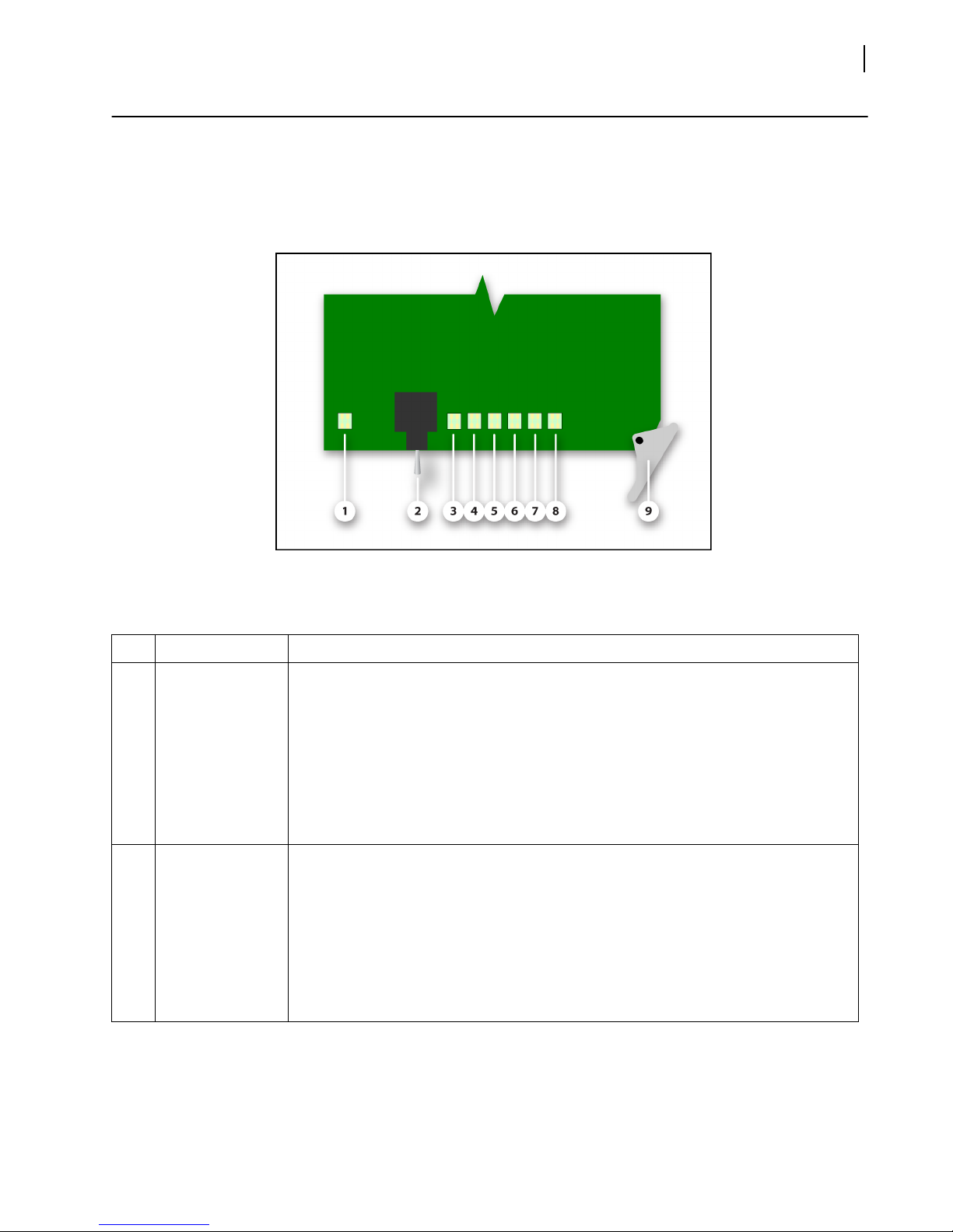
Figure 1-1 is a generic top-front view of the SRC6800+ module.
Figure 1-1 SRC6800+ Front Module Card Edge Features
Table 1-1 SRC6800+ Front Module Card Edge Features
Feature Description
1 Module Status
LED
Indicates the module’s state of operation.
Off - The module is powered OFF. The module is not operational.
Green - The module is powered ON. The module is operating properly.
Red - The module is either booting or experiencing an error.
Red (blinking) - The module has booted in ‘safe mode’. See ‘Toggle Switch’
description below.
Amber - The module is booting.
2 Ethernet Toggle
Switch
This three-position toggle switch controls the card’s IP address configuration.
Up (after boot) - Forces the IP address for HTTP and Telnet configuration and
control to 192.168.1.1
Up (during boot) - Forces the module into ‘safe mode’.
See Firmware Upgrade for details.
Center - The module operates using the configured IP address.
Down - Disables HTTP and Telnet access.

Chapter 1
SRC6800+ Module and Interface
4
Copyright © 2011, Harris Corporation
3–6 RF Input LEDs 1–4 This LED indicates the state of the configured active RF input.
Off - The Interface is not configured for use.
Green - The interface is active and operating normally.
Red - The interface is experiencing a Loss of Signal (LOS).
Amber - The interface is experiencing errors.
7 ASI Input LED This LED indicates the state of the ASI Input.
Off - The Interface is not configured for use.
Green - The interface is active and operating normally.
Red - The interface is experiencing a Loss of Signal (LOS).
Amber - The interface is experiencing errors.
8 Ethernet Status
LED
This LED indicates the status of the Ethernet connection.
Off - The module is powered Off. The module is not operational.
Green- The Ethernet interface is operating in 100 BaseT mode.
Red- The Ethernet interface is does not have link.
Amber - The Ethernet interface is operating in 10 BaseT mode.
Table 1-1 SRC6800+ Front Module Card Edge Features
Feature Description
SRC6800+
Installation and Operation Manual
5
Copyright © 2011, Harris Corporation
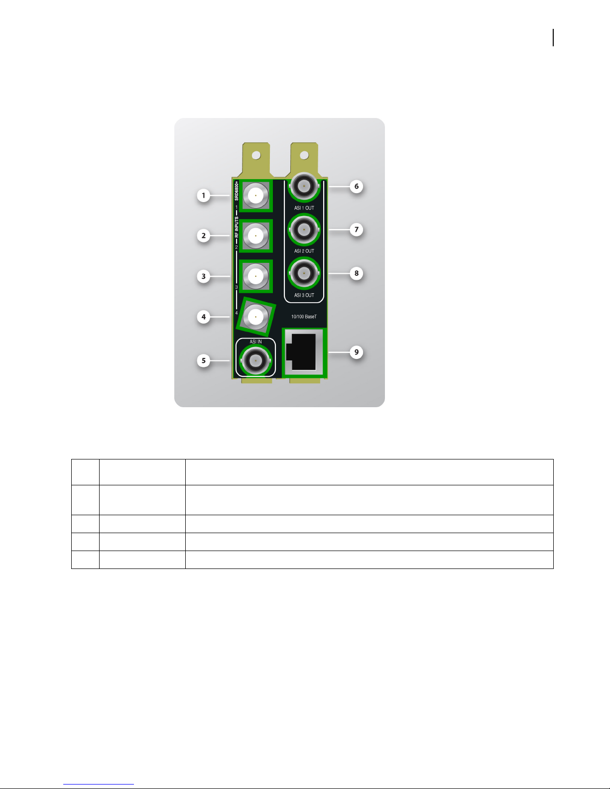
SRC6800+ Back Connector
Figure 1-2 shows the double-slot back connector used by the SRC6800+ when installed in
a 6800+.
Figure 1-2 SRC6800+ Back Connector
Table 1-2 SRC6800+ Back Connector Electrical Interfaces
Ite
mDescription Full Description
1–4 RF Inputs Hard-wire RF inputs to up to four different sources and use software selection to
determine the active input.
5 ASI Input Interface for receiving ASI input directly.
6–8 ASI Outputs Provides three duplicate copies of the processed SPTS/MPTS ASI signal.
9 Ethernet Interface 10/100 BaseT Ethernet Connection

Chapter 1
SRC6800+ Module and Interface
6
Copyright © 2011, Harris Corporation
Electrical Interfaces
RF Inputs
The SRC6800+ features four RF interfaces for applications in which more than one satellite
input is required. The ‘live’ input is software-selectable amongst these interfaces. Each
interface receives L-band satellite input through a 75-Ohm F-type female connector.
Additionally these RF interfaces can also provide voltage for Low Noise Block (LNB) down
converter power and control.
CAUTION In applications requiring the SRC6800+ to supply LNB power an
additional 1-slot filler plate must be installed immediately to the right of the
SRC6800+ to accommodate power requirements.
ASI In
This interface allows demultiplexing and decryption of a transport stream originating on
external equipment.
This ASI connections require 75-Ohm characteristic impedance coaxial cable. In general,
reliable operation can be achieved with cable lengths of up to 100 meters.
ASI Out
These interfaces provide duplicate copies of the demodulated signal received on the
configured L-band input, or of the signal received on the ASI input, decrypted and
demultiplexed according to the module's configuration.
All ASI connections require 75-Ohm characteristic impedance coaxial cable. In general,
reliable operation can be achieved with cable lengths of up to 100 meters.
Table of contents
Other Imagine communications Receiver manuals


