manuals.online logo
Brands
  1. Home
  2. •
  3. Brands
  4. •
  5. Sony
  6. •
  7. Receiver
  8. •
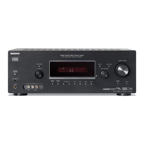
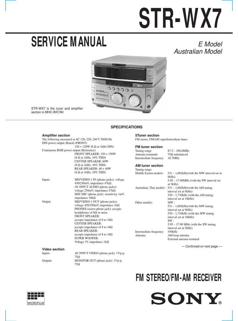
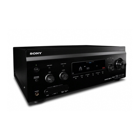
  9. Sony STR-DE598 - A/v Receiver User manual

Sony STR-DE598 - A/v Receiver User manual

Other manuals for STR-DE598 - A/v Receiver

7

Other Sony Receiver manuals

Sony STR-DA3300ES - Multi Channel Av Receiver User manual

Sony

Sony STR-DA3300ES - Multi Channel Av Receiver User manual

Sony STR-DA4400ES User manual

Sony

Sony STR-DA4400ES User manual

Sony VGP-MR100U - Room Link 2 Instruction Manual

Sony

Sony VGP-MR100U - Room Link 2 Instruction Manual

Sony STR-DV10 - Fm Stereo/fm-am Receiver Quick start guide

Sony

Sony STR-DV10 - Fm Stereo/fm-am Receiver Quick start guide

Sony STR-DN1050 User manual

Sony

Sony STR-DN1050 User manual

Sony AIR-A10R - Wireless Audio Receiver Component User manual

Sony

Sony AIR-A10R - Wireless Audio Receiver Component User manual

Sony STR-DA5000ES - Fm Stereo/fm-am Receiver User manual

Sony

Sony STR-DA5000ES - Fm Stereo/fm-am Receiver User manual

Sony STR-DE575 - Fm Stereo/fm-am Receiver User guide

Sony

Sony STR-DE575 - Fm Stereo/fm-am Receiver User guide

Sony HCD-GPX555 User manual

Sony

Sony HCD-GPX555 User manual

Sony IAD-IF70 User manual

Sony

Sony IAD-IF70 User manual

Sony CMA-87 User manual

Sony

Sony CMA-87 User manual

Sony STR-313L User manual

Sony

Sony STR-313L User manual

Sony STR-DN1010 - Multi Channel Av Receiver User manual

Sony

Sony STR-DN1010 - Multi Channel Av Receiver User manual

Sony HCD-FX900KW User manual

Sony

Sony HCD-FX900KW User manual

Sony ICF-SC1 User manual

Sony

Sony ICF-SC1 User manual

Sony TR-8460 User manual

Sony

Sony TR-8460 User manual

Sony AC-300MD User manual

Sony

Sony AC-300MD User manual

Sony STR-D615 - Fm-am Receiver User manual

Sony

Sony STR-D615 - Fm-am Receiver User manual

Sony STR-GX9O0ES User manual

Sony

Sony STR-GX9O0ES User manual

Sony BKM-142HD User manual

Sony

Sony BKM-142HD User manual

Sony STR-DN1010 - Multi Channel Av Receiver User manual

Sony

Sony STR-DN1010 - Multi Channel Av Receiver User manual

Sony SAT-HD300 - High Definition Satellite... User manual

Sony

Sony SAT-HD300 - High Definition Satellite... User manual

Sony AC-PW20 User manual

Sony

Sony AC-PW20 User manual

Sony STR-DA6400ES - Multi Channel Av Receiver User manual

Sony

Sony STR-DA6400ES - Multi Channel Av Receiver User manual

Popular Receiver manuals by other brands

Televes ZAS HD SAT user manual

Televes

Televes ZAS HD SAT user manual

Realistic DX-75 Operating and service instructions

Realistic

Realistic DX-75 Operating and service instructions

Saris 4620 Assembly instructions

Saris

Saris 4620 Assembly instructions

Mini DTR 206C PVR user manual

Mini

Mini DTR 206C PVR user manual

RF Elements TwistPort manual

RF Elements

RF Elements TwistPort manual

Denon DN-200WS user guide

Denon

Denon DN-200WS user guide

Yamaha RX-V467 owner's manual

Yamaha

Yamaha RX-V467 owner's manual

Russound SaphIR 858 instruction manual

Russound

Russound SaphIR 858 instruction manual

Quasonix RDMS Firmware update procedure

Quasonix

Quasonix RDMS Firmware update procedure

Pioneer XV-HTD1 Service manual

Pioneer

Pioneer XV-HTD1 Service manual

ATZ HDMI-V2-44HE150 manual

ATZ

ATZ HDMI-V2-44HE150 manual

Grundig STR 7122 TWIN Service manual

Grundig

Grundig STR 7122 TWIN Service manual

Creative Blaster Modem user guide

Creative

Creative Blaster Modem user guide

Panduit ATLONA AT-OME-RX11 installation guide

Panduit

Panduit ATLONA AT-OME-RX11 installation guide

VOLTCRAFT UTPS-40 operating instructions

VOLTCRAFT

VOLTCRAFT UTPS-40 operating instructions

JVC KW-ADV794 instructions

JVC

JVC KW-ADV794 instructions

Litelink VT-1001 operating instructions

Litelink

Litelink VT-1001 operating instructions

Sangean WR-11 Service manual

Sangean

Sangean WR-11 Service manual

manuals.online logo
manuals.online logoBrands
  • About & Mission
  • Contact us
  • Privacy Policy
  • Terms and Conditions

Copyright 2025 Manuals.Online. All Rights Reserved.

2-549-732-14(1 )
SONY:
FM Stereo
FM/AM Receiver
Operating Instructions
Owner's Record
The model and serial numbers are located on the rear of the unit. Record the serial
number in the space provided below. Refer to them whenever you call upon your
Sony dealer regarding this prodnct.
Model No. Serial No.
STR-DE598
@2005 Sony Corporation
To prevent fire or shock hazard, do not
expose the unit to rain or moisture.
To prevent fire do not cover the ventilation of the
apparatus with newspapers, table-cloths, curtains, etc.
And don't place lighted candles on the apparatus.
To prevent fire or shock hazard, do not place objects
filled with liquids, such as vases, on the apparatus
Do not install the appliance m a confined space,
such as a bookcase or built-in cabinet.
Don't throw away batteries with
general house waste; dispose of
them correctly as chemical waste
Disposal of Old Electrical &
Electronic Equipment
(Applicable in the European
Union and other European
countries with separate
collection systems)
This symbol on the product or on
its packaging indicates that this
product shall not be tieated as
household waste. Instead it shall be
handed over to the applicable collection point tbr the
recycling of electrical and electronic equipment. By
ensming this pro&_ct is disposed of correctly, you will
help prevent potential negative consequences for tile
environment and human health, which could othelavise
be caused by inappropriate waste handling of this
product The recycling of materials will help to
consel_ie nattlral resources. For nlore detailed
information about recycling of this product, please
contact your local city office, your household waste
disposal service or the shop where you purchased the
product
For customers in the United States
This symbol is intended to ale_t
the user to the presence of
uninsulated "dangerous voltage"
within the product's enclosure
that may be of sufficient
magnitude to constitute a risk of
electric shock to persons.
This symbol is intended to ale_t
the user to the presence of
impmtant operating and
maintenance (se_"_,icing)
instructions in the literature
accompanying the appliance.
WARNING
This eqtfipment has been tested and found to colnply
with the limits for a Class B digital device, pmsuam to
Part 15 of the FCC Rules. These limits are designed to
provide reasonable protection against hannfifl
interference in a residential installation. This
equipment generates, uses, and can radiate radio
fiequency energy and, if not installed and used in
accordance with the instructions, may canse harmfifl
interference to radio communications. However, there
is no guarantee that interference will not occur in a
particular installation. If this equipment does canse
hmmfifl interference to radio or television reception,
which can be determined by turning the equipment off
and on, the user is encouraged to t_" to correct tile
interference by one or mo_e of the tbllowing measures:
Reorient or relocate the receiving antenna.
Increase the separation between the equipment and
receiver
Connect the equipment into an outlet on a circuit
different fiom that to which the receiver is
connected.
Consult the deale_ or an experienced radioiTV
technician for help.
CAUTION
You are cautioned that any changes or modification not
expressly approved in this manual could void your
anthority to operate this equipment.
2GB
Note to CATV system installer:
This reminder is provided to call CATV system
installer's attention to A_ticle 820-40 of the NEC that
provides guidelines for proper grotmding and, m
pmticular, specifies that the cable ground shall be
connected to the grotmding system of the building, as
close to the point of cable era; 7 as practical.
For customers in Canada
CAUTION
TO PREVENT ELECTRIC SHOCK, MATCH WIDE
BLADE OF PLUG TO WIDE SLOT FULLY
INSERT.
For customers in the United States,
Canada and Australia
ENERGY STAR y: is a U.S. iegistered
mark. As an ENERGY STAR x_paimer,
Sony Corporation has determined that
this product meets the ENERGY STAR "_
guidelines tbr energy efficiency.
About This Manual
•The instructions in this manual are fbr model
STR-DE598 Check your model number by looking
at the lower right comer of the flont panel. In this
manual, the models of area code U is used tbr
illusmltion proposes mfless stated othelwise
• The instructions in this manual describe the connols
on the receiver. You can also use the controls on the
supplied remote if they have the same or similar
names as those on the receiver Fo_ details on the use
of your remote, seepages 44 47
About area codes
The area code of the receiva you purchased is
shown on the lower portion of the rear panel (see
the illusnation below).
Area code
Any diflhrences in operation, according to the area
code, are clearly indicated in the text, for example,
"Models of area code AA only".
This receiver incmporates Dolby* Digital and Pro
Logic Surround and the DTS** Digital Sunound
System.
* Manufactured under license from Dolby
Laboratories
"Dolby", "Pro Logic" and the double-D symbol are
trademarks of Dolby Laboratories
** "DTS", "DTS-ES", "Neo:6" and "DTS 96/24" are
trademarks of Digital Theater Systems, Inc.
3GB
Getting Started
l : Check how to hookup your
components ....................................... 5
1a: Connecting components with
digital audio output jacks ........... 7
1b: Connecting components with
nmlti channel output jacks ........ 10
1c: Connecting components with only
analog audio jacks .................... 12
2: Connecting the antennas ................... 14
3: Connecting speakers ......................... 15
4: Connecting the AC power cord ........ 17
5: Setting up the speakers ..................... 18
6: Adjusting the speaker levels and
balance ............................................ 21
TEST TONE
Amplifier Operation
Selecting the component ....................... 22
Listening to multi channel sound .......... 23
MULTI CH IN
Listening to FMiAM radio .................... 23
Storing FM stations automatically ........ 24
AUTOBETICAL
(Models of area code CEL, CEK
only)
Presetting radio stations ........................ 25
Using the Radio Data System (RDS).... 26
(Models of area code CEL, CEK
only)
(?hanging the display ............................. 27
About the indications in the display ...... 28
Enjoying Surround Sound
Using only the fi'ont speakers ............... 30
Enjoying higher fidelity sound .............. 30
AUTO FORMAT DIRECT
Selecting a sound field .......................... 32
Selecting the sun'ound back decoding
mode ............................................... 34
SURR BACK DECODING
Advanced Adjustments and
Settings
Assigning the component video input .. 36
COMPONENT VIDEO
INPUT ASSIGN
(Except for models of area code
(;EL, CEK)
Switching the audio input mode for digital
components ..................................... 36
INPUT MODE
Customizing sound fields ..................... 37
Adjusting the tone ................................. 38
Advanced settings ................................. 39
Other Operations
Naming preset stations and inputs ........ 4 l
Using the Sleep Timer .......................... 42
Selecting the speaker system ................ 42
Recording ............................................. 43
Operations Using the Remote
RM-AAUO01
Before you use your remote .................. 44
Remote button description .................... 44
(?hanging the factory setting of an input
button .............................................. 47
Additional Information
Precautions ........................................... 48
Troubleshooting .................................... 49
Specifications ....................................... 51
List of button locations and reference
pages ............................................... 55
Index ......................................... Back page
4g8
Steps la through ic beginning on page 7 describe how to hook up your components to this receiver.
Be/bre you begin, refer to "Connectable components" below/'or the pages which describe how to
connect each component.
After hooking up all your components, proceed to "2: Connecting the antennas" (page 14).
Connectable components
Component to be connected Page
DVD player
With digital audio output a) 7 8
With multi channel audio output b) 10 11
With analog audio output onlv c) 7 8
TV monitor
With component video input d) 8 or 11
With composite video input only 13
Satellite tuna
With digital audio output a) 7 8
With analog audio output only c) 7 8
Super Audio CD/CD player
With digital audio output a) 9
With multi channel audio output b) 10
With analog audio output onl} x) 12
MD'Tape deck
With analog audio output onlv c) 12
Multi channel decoder 10
VCR, camcordez, video game, etc. 13
a) Model with a DIGITAL OPTICAL OUTPUT or DIGITAL COAXIAL OUTPUT jack, etc
b) Model with MULTI CH OUTPUT jacks, etc. This connection is used to output the audio decoded by the
component's internal multi channel decodes through this receiver.
c) Model equipped only with AUDIO OUT L R jacks, etc.
d> Model with component video (Y, PBiCB/B-Y, PR_CR/R-Y) input jacks.
Q
.g
_a
e,
continued
5Gs
Required cords
The hookup diagrams on the subsequent pages assume the use of the following optional connection
cords ([] to r_) (not supplied).
[] Audio cord
White (k)
Red (R)
[] Audio/video cord
Yellow (video)
White (L/audio)
Red (R/audio)
[] Video cord
Ye;Iow _
[] Optical digital cord
[] Coaxial digital cord
[] Monaural audio cord
Black @ @
Tip
Audio cord [] can be tom into two monaural andio
cords r_
[] Component video cord
(Except for models of area code CEL, CEK)
Green
Blue
Red
Notes
•Tmn off tile power to all components befme making any connections.
• Be sure to make connections firmly to avoid hum and noise.
• When connecting an audio'video cord, be sine to match the color-coded pins to the appropriate jacks on the
components: yellow (video) to yellow; white (left, audio) to white and red (right, audio) to red.
• When connecting optical digital cords, inse_t the cord plugs straight in lmtil they click into place.
• Do not bend or tie optical digital cords
668
Q
Hooking up a DVD player, TV monitor or satellite tuner w,
_Q
For details o,1the required cords (_i'_ r_), see page 6.
1 Connect the audio jacks.
OPTIC
DVD player
1
[]
[]
[]
[]
Satellite tuner _
Note
You can also listen to the sotmd of your TV by connecting your TV's andio output jacks to the VIDEO 2 AUDIO IN
jacks on the receiver In this case, do not connect the TV's video output jack to the VIDEO 2 VIDEO IN jack on the
receiver.
continued 7Gs
2 Connect the video jacks.
(Except for models of area code (_'EL, (EK) The following illustration shows how to connect a TV or
satellite tuner and a DVD player with COMPONENT VIDEO (Y, PBiCBiB-Y, PR CR R-Y) output
jacks. Connecting a TV with component video input jacks allows you to enjoy higher quality video.
_x
_PT_,>'L
VD Li
IC221
[,
_ ,@IF,Q2®
Note
On this receiver, the standaid video signals cannot be converted to component video signals (o_ vice versa)
8GB
Hooking up a Super Audio CD/CD player
For details on the required cords (_'1 1"_1), see page 6. Q
w_
Tip
All the digital andio jacks a_e compatible with 32 kHz, 44 1kHz, 48 kHz and 96 kHz sampling fiequencies
Note
The sound is not output when you play a Sl_er Audio CD on the Sl_er Audio CD player connected to the
SA-CD'CD OPTICAL IN jack on this receiver Connect to the analog input jacks (SA-CD'CD IN jacks). Refer to
the operating instructions supplied with the Supa Audio CD player.
9GB
1 Connect the audio jacks.
If your DVD or Super Audio CD player is equipped with multi channel output jacks, yon can connect
it to this receiver's MULTI CH IN jacks to enjoy the multi channel sound. Alternatively, the multi
channel input jacks can be used to connect an external multi channel decoder.
For details on the required cords (ri_ r_), see page 6.
ASSiGNaBlE
/",N S ",N /7 "x
DVD player,
Super Audio CD player,
Multi channel decoder, etc
Tip
This connection also allows you _oenjoy sofiwaze with multi chaimel audio zecolded in fbnnats other than the Dolby
Digital and DTS.
Note
When you make connections to the MULTI CH IN jacks you will need to adjust the level of the speakezs and sub
woofer using the cont!ols on the connected component.
10_