Imagine communications Selenio 6800 User manual
Revision: A
Delivering the Moment
Selenio 6800™ ACO6800+
Dual AES Automatic Change Over
175-100470-00
Installation and Operation Manual

Publicaon Informaon
© 2014 Imagine Communicaons Corp. Proprietary and Condenal.
Imagine Communicaons considers this document and its contents to be proprietary and condenal.
Except for making a reasonable number of copies for your own internal use, you may not reproduce this
publicaon, or any part thereof, in any form, by any method, for any purpose, or in any language other
than English without the wrien consent of Imagine Communicaons. All others uses are illegal.
This publicaon is designed to assist in the use of the product as it exists on the date of publicaon of this
manual, and may not reect the product at the current me or an unknown me in the future. This pub-
licaon does not in any way warrant descripon accuracy or guarantee the use for the product to which
it refers. Imagine Communicaons reserves the right, without noce to make such changes in equipment,
design, specicaons, components, or documentaon as progress may warrant to improve the perfor-
mance of the product.
Trademarks
6800+™, ADC™, CCS Navigator™, Channel ONE™, ChannelView™, ClipSync™, Delay™, D Series™, D Se-
ries DSX™, Deliver the Moment™, Delivering the Moment™, FAME™, Farad™, G8™, G Scribe™, HView™,
IconMaster™, IconLogo™, IconStaon™, IconKey™, InfoCaster™, InfoCaster Creator™, InfoCaster Manag-
er™, InfoCaster Player™, InstantOnline™, Invenio®, Live Update™, mCAPTURE™, Magellan™, Magellan CCS
Navigator™, Magellan Q SEE™, MulService SDN™, NetPlus™, NetVX™, NewsForce™, Nexio® G8™, Nexio
AMP® ChannelView™, Nexio® Channel ONE™, Nexio® ClipSync™, Nexio® Delay™, Nexio® Digital Turnaround
Processor™, Nexio® Farad™, Nexio® G Scribe™, Nexio® IconKey™, Nexio® IconLogo™, Nexio® IconMaster™,
Nexio® IconStaon™, Nexio® InfoCaster™, Nexio® InfoCaster Creator™, Nexio® InfoCaster Manager™,
Nexio® InfoCaster Player™, Nexio® InfoCaster Trac™, Nexio® InstantOnline™, Nexio® mCAPTURE™, Nexio®
NewsForce™, Nexio® NXIQ™, Nexio® Playlist™, Nexio® Remote™, Nexio®RTX Net™, Nexio® TitleMoon™,
Nexio® TitleOne™, Nexio® Velocity ESX™, Nexio® Velocity PRX™, Nexio® Velocity XNG™, Nexio® Volt™,
OPTO+™, Panacea™, Planum™, Playlist™, Predator II GRF™, Predator II GX™, Punctuate™, Remote™, RTX
Net™, QuiC™, Q SEE™, SD STAR™, Selenio™, Selenio 6800+™, SelenioNext™, Selenio X50™, Selenio X85™,
Selenio X100™, TitleMoon™, TitleOne™, Velocity ESX™, Velocity PRX™, Velocity XNG™, Versio™,
Videotek® SD STAR™, X50™, and X85™ are trademarks of Imagine Communicaons or its subsidiaries.
Altude Express®, Connectus®, Enabling PersonalizedTV®, ICE® Broadcast System, ICE Illustrate®,
ICE Q® algorithms, ICEPAC®, Imagine ICE®, Inscriber®, Inscriber® Connectus®, Invenio®, NEO®, Nexio®,
Nexio AMP®, PersonalizedTV®, RouterWorks®, Videotek®, Videotek® ASI STAR®, Videotek® GEN STAR®,
and Videotek® HD STAR® are registered trademarks of Imagine Communicaons or its subsidiaries.
Microso® and Windows® are registered trademarks of Microso Corporaon. HD BNC is a trademark of
Amphenol Corporaon. Some products are manufactured under license from Dolby Laboratories. Dolby
and the double D symbol are registered trademarks of Dolby Laboratories. DTS Neural audio products are
manufactured under license from DTS Licensing Limited. DTS and the Symbol are registered trademarks &
the DTS Logos are trademarks of DTS, Inc. © 2008 2010 DTS, Inc. All other trademarks and trade names are
the property of their respecve companies.
Contact Informaon
Imagine Communicaons has oce locaons around the world. For locaons and contact informaon see:
hp://www.imaginecommunicaons.com/contact us/
Support Contact Informaon
For support contact informaon see:
▪Support Contacts: hp://www.imaginecommunicaons.com/services/technical support/
▪eCustomer Portal: hp://support.imaginecommunicaons.com
© 2014 Imagine Communicaons Corp. Proprietary and Condenal

Edition A
July 2013
ACO6800+AES
Dual AES Automatic Change Over
Installation
and Operation Manual

iii
Contents
Preface..........................................................................................................................v
Manual Information .......................................................................................................v
Purpose ......................................................................................................................v
Audience ....................................................................................................................v
Revision History ..........................................................................................................v
Writing Conventions ...................................................................................................v
Obtaining Documents ................................................................................................vi
Unpacking/Shipping Information ................................................................................vi
Unpacking a Product .................................................................................................vi
Product Servicing .......................................................................................................vi
Returning a Product ................................................................................................... vi
Restriction on Hazardous Substances (RoHS) Directive ............................................... vii
Waste from Electrical and Electronic Equipment (WEEE) Directive .............................. vii
Safety ........................................................................................................................... viii
Safety Terms and Symbols in this Manual ................................................................ viii
Chapter 1 Introduction.............................................................................................................. 1
Product Description ....................................................................................................... 1
Key Features .................................................................................................................. 1
ACO6800+AES+BD .................................................................................................... 1
ACO6800+AES+CD ................................................................................................... 1
ACO6800+AES+CDL ................................................................................................. 2
Other Common Features: .......................................................................................... 2
ACO6800+AES Packages ........................................................................................... 2
Back Module .................................................................................................................. 3
Signal Flow .................................................................................................................... 3
Chapter 2 Installation and Operation................................................................................ 5
Unpacking the Module ................................................................................................. 5
Setting Jumpers ............................................................................................................ 5
Maximum Frame Power Ratings .................................................................................. 6
Installing ACO6800+AES Modules ............................................................................... 7
Upgrading Module Firmware ....................................................................................... 7
Operating Notes ............................................................................................................ 7

iv
Changing Parameter Settings .......................................................................................8
Recalling Default Parameter Settings .......................................................................... 8
Changing Parameter Settings Using CCS Software .....................................................9
Reading Software and Hardware Versions .................................................................. 9
Audio Configuration ................................................................................................... 10
Switch Settings with the 2X4 Work Mode ................................................................ 10
Switch Setting with 1X8 Work Mode .......................................................................11
Sample Scenario One: Parameter Settings ................................................................13
Sample Scenario One: Chain of Events ..................................................................... 14
Sample Scenario Two: Parameter Settings ................................................................ 14
Sample Scenario Two: Chain of Events .....................................................................15
ACO6800+AES Control Parameters ............................................................................16
Parameter List .......................................................................................................... 16
LEDs and Alarms ..........................................................................................................18
Monitoring LEDs ...................................................................................................... 18
..................................................................................................Module Status LEDs 19
Alarms ..................................................................................................................... 19
Chapter 3 Specifications......................................................................................................... 21
Audio Input .................................................................................................................. 21
Audio Output ...............................................................................................................22
Propagation Delay .......................................................................................................23
Power Consumption ....................................................................................................23
Appendix A Communication and Control Troubleshooting Tips.............................25
Software Communication Problems .......................................................................... 25
Hardware Communication Problems .........................................................................27
Index........................................................................................................................... 29

v
Preface
Manual Information
Purpose This manual details the features, installation, operation, maintenance, and specifications for
the ACO6800+AES Dual AES Automatic Change Over.
Audience This manual is written for engineers, technicians, and operators responsible for the
installation, setup, and/or operation of the ACO6800+AES Dual AES Automatic Change
Over.
Revision
History
Writing
Conventions
To enhance your understanding, the authors of this manual have adhered to the following
text conventions:
Table P-1 Document Revision History
Edition Date Revision History
Preliminary July 2013 First release
Table P-2 Writing Conventions
Term or
Convention Description
Bold Indicates dialog boxes, property sheets, fields, buttons, check boxes, list
boxes, combo boxes, menus, submenus, windows, lists, and selection
names
Italics Indicates E-mail addresses, the names of books or publications, and the
first instances of new terms and specialized words that need emphasis
CAPS Indicates a specific key on the keyboard, such as ENTER, TAB, CTRL, ALT,
or DELETE
Code Indicates variables or command-line entries, such as a DOS entry or
something you type into a field
> Indicates the direction of navigation through a hierarchy of menus and
windows

Preface
vi
Obtaining
Documents
Product support documents can be viewed or downloaded from our website. Alternatively,
contact your Customer Service representative to request a document.
Unpacking/Shipping Information
Unpacking a
Product
This product was carefully inspected, tested, and calibrated before shipment to ensure years
of stable and trouble-free service.
1Check equipment for any visible damage that may have occurred during transit.
2Confirm that you have received all items listed on the packing list.
3Contact your dealer if any item on the packing list is missing.
4Contact the carrier if any item is damaged.
5Remove all packaging material from the product and its associated components before you
install the unit.
Keep at least one set of original packaging, in the event that you need to return a product
for servicing.
Product
Servicing
Except for firmware upgrades, the modules are not designed for field servicing. All
hardware upgrades, modifications, or repairs require you to return the modules to the
Customer Service center.
Returning a
Product
In the unlikely event that your product fails to operate properly, contact Customer Service to
obtain a Return Authorization (RA) number, and then send the unit back for servicing. If the
original package is not available, you can supply your own packaging as long as it meets the
following criteria:
The packaging must be able to withstand the product’s weight.
The product must be held rigid within the packaging.
There must be at least 2 in. (5 cm) of space between the product and the container.
The corners of the product must be protected.
Ship products back to us for servicing prepaid and, if possible, in the original packaging
material. If the product is still within the warranty period, we will return the product prepaid
after servicing.
hyperlink Indicates a jump to another location within the electronic document or
elsewhere
Internet
address
Indicates a jump to a website or URL
Indicates important information that helps to avoid and troubleshoot
problems
Table P-2 Writing Conventions (Continued)
Term or
Convention Description

ACO6800+AES
Installation and Operation Manual
vii
Restriction on Hazardous Substances (RoHS) Directive
Directive 2002/95/EC—commonly known as the European Union (EU) Restriction on
Hazardous Substances (RoHS)—sets limits on the use of certain substances found in
electrical and electronic equipment. The intent of this legislation is to reduce the amount of
hazardous chemicals that may leach out of landfill sites or otherwise contaminate the
environment during end-of-life recycling. The Directive, which took effect on July 1, 2006,
refers to the following hazardous substances:
Lead (Pb)
Mercury (Hg)
Cadmium (Cd)
Hexavalent Chromium (Cr-V1)
Polybrominated Biphenyls (PBB)
Polybrominated Diphenyl Ethers (PBDE)
In accordance with this EU Directive, products sold in the European Union will be fully
RoHS-compliant and “lead-free.” Spare parts supplied for the repair and upgrade of
equipment sold before July 1, 2006 are exempt from the legislation. Equipment that
complies with the EU directive will be marked with a RoHS-compliant symbol, as shown in
Figure P-1.
Figure P-1 RoHS Compliance Symbol
Waste from Electrical and Electronic Equipment (WEEE) Directive
The European Union (EU) Directive 2002/96/EC on Waste from Electrical and Electronic
Equipment (WEEE) deals with the collection, treatment, recovery, and recycling of electrical
and electronic waste products. The objective of the WEEE Directive is to assign the
responsibility for the disposal of associated hazardous waste to either the producers or users
of these products. As of August 13, 2005, producers or users are required to recycle
electrical and electronic equipment at end of its useful life, and must not dispose of the
equipment in landfills or by using other unapproved methods. (Some EU member states
may have different deadlines.)
In accordance with this EU Directive, companies selling electric or electronic devices in the
EU will affix labels indicating that such products must be properly recycled. Contact your
local Sales representative for information on returning these products for recycling.
Equipment that complies with the EU directive will be marked with a WEEE-compliant
symbol, as shown in Figure P-2.
Figure P-2 WEEE Compliance Symbol
Preface
viii
Safety Carefully review all safety precautions to avoid injury and prevent damage to this product or
any products connected to it. If this product is rack-mountable, it should be mounted in an
appropriate rack using the rack-mounting positions and rear support guides provided. To
protect a frame from circuit overloading, connect each frame to a separate electrical circuit.
If this product relies on forced air cooling, all obstructions to the air flow should be removed
prior to mounting the frame in the rack.
If this product has a provision for external earth grounding, ground the frame to the earth
using the protective earth ground on the rear panel.
IMPORTANT! Only qualified personnel should perform service procedures.
Safety Terms and Symbols in this Manual
WA R N I N G
Statements identifying conditions or practices that may result in personal
injury or loss of life. High voltage is present.
CAUTION
Statements identifying conditions or practices that can result in damage
to the equipment or other property.

1
1Introduction
Product Description
The ACO6800+AES Dual AES Automatic Change Over supports both 2X4 and 1X8 AES/EBU
distribution modes, with four copies of the input signal. The module supports audio
sampling frequencies from 30 kHz to 192 kHz, and is available in balanced, unbalanced, and
unbalanced loopthrough versions. Cable equalization and reclocking enable reliable recovery
for incoming digital audio signals, jitter reduction, and extended cable length.
Key Features
The ACO6800+AES is available in three versions, providing the features described below:
ACO6800+AES+BD
Provides dual 1x4 AES changeover or single 1x8 distribution amplifier with ACO
Supports balanced inputs/outputs at 110Ω
Supports clock signals between 30KHz to 192KHz compatibility (independent for each
input channel)
Supports reclocked outputs
Provides balanced input at 110Ω(±20% impedance) and a maximum input amplitude
of 7 V pk-to-pk, and an output amplitude of 2 to 7 V pk-to-pk into a 110Ωload
Provides fully isolated transformer-coupled inputs and outputs
ACO6800+AES+CD
Provides dual 1x4 AES changeover or single 1x8 distribution amplifier with ACO
Supports unbalanced inputs/outputs 75Ω
Supports clock signals between 30KHz to 192KHz compatibility (independent for each
input channel)
Supports SMPTE 276M for AES audio on 75Ωcoax
Supports reclocked outputs
Provides unbalanced Input, at 75Ωimpedance, <100mV sensitivity, 0.1 to 1 V pk-to-pk
(±10%) and unbalanced output at 75Ωimpedance, 1.0V (±10%) peak-to-peak into a
75Ωload

Chapter 1
Introduction
2
ACO6800+AES+CDL
Same features as ACO6800+AES+CD
Additionally supports one passive loop per channel on back module
Other Common Features:
Remote monitoring via SNMP using Navigator or Web Server control
Support sample frequency indication for standard AES signal
Card Edge indicators for Alarm
Card Edge LEDs
2x4 / 1x8 mode indicator
AES input indicator
Audio Signal present detection
Alarms to monitor input signal presence
Microprocessor-controlled with internal flash ram for storing configuration
Automatic mode using internal signal analysis with alarm parameters
Manual change-over by local frame controller
Hot Swappable
CCS-P / SNMP support
ACO6800+AES Packages
Table 1-1 Available Product Packages
Product Description
ACO6800+AES+BD 2x4 AES Audio Automatic Change Over and DA
Provides dual independent channels with balanced 1 input/4 reclocked outputs, or
AES DA with 1x8 ACO
ACO6800+AES+CD 2x4 AES Audio Automatic Change Over and DA
Provides dual independent channels with unbalanced 1 input/4 reclocked outputs,
or AES DA with 1x8 ACO
ACO6800+AES+CDL 2x4 AES Audio Automatic Change Over and DA
Provides dual independent channels with passive loopthrough for unbalanced
1 input/3 reclocked outputs, or AES DA with 1x6 ACO

ACO6800+AES
Installation and Operation Manual
3
Back Module
Figure 1-1 ACO6800+AES Back Modules
Signal Flow
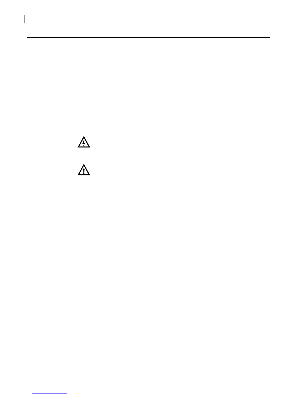
Figure 1-2. ACO6800+AES+BD Signal Flow Diagram
+
-
G
+
-
G
1
+
-
G
2
+
-
G
3
+
-
G
4
+
-
G
+
-
G
1
+
-
G
2
+
-
G
3
+
-
G
4
AB
AB
AC O6 80 0 + AE S+ B D
AES
IN
A
E
S
O
U
T
ACO6800+AES+CD
AES
1
4
3
2
1
4
3
2
AES
IN
AB
AB
OUT
ACO6800+AES+CDL
AES
1
4
3
2
1
4
3
2
LOOP
AES
IN
LOOP
AB
AB
OUT
ACO6800+AES+BD ACO6800+AES+CDL
ACO6800+AES+CD
Input Buffer
Detection
GND +–
Driver
GND+
–
Driver
GND+–
Driver
GND+–
Driver
GND+–
Driver
GND+–
Driver
GND+–
Driver
GND +–
Driver
GND +
–
Mux
Balanced >
Unbalanced
Transformer
Unbalanced >
Balanced
Transformer
Control
Unbalanced >
Balanced
Transformer
Unbalanced >
Balanced
Transformer
Unbalanced >
Balanced
Transformer
Unbalanced >
Balanced
Transformer
Unbalanced >
Balanced
Transformer
Unbalanced >
Balanced
Transformer
Unbalanced >
Balanced
Transformer
Input Buffer
GND +–
Balanced >
Unbalanced
Transformer
Detection
Switch
Control
AES Out A1
AES Out A2
AES Out A3
AES Out A4
AES Out B2
AES Out B3
AES Out B4
AES Out B 1
AES In A
AES In B
Chapter 1
Introduction
4
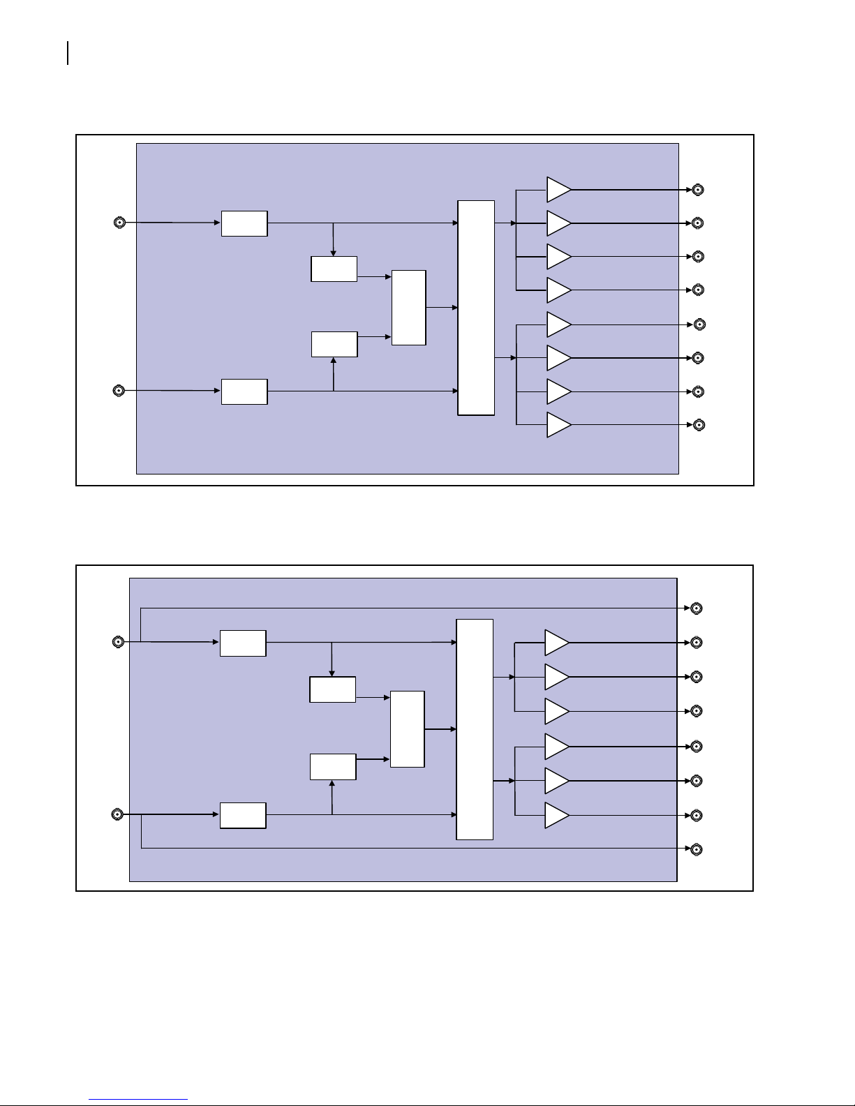
Figure 1-3. ACO6800+AES+CD Signal Flow
Figure 1-4. ACO6800+AES+CDL Signal Flow
Input Buffer
Detection
Driver
Driver
Driver
Driver
Driver
Driver
Driver
Driver
Mux
Control
Input Buffer
Detection
Switch
Control
AES In A
AES In B
AES Out A1
AES Out A2
AES Out A3
AES Out A4
AES Out B2
AES Out B3
AES Out B4
AES Out B 1
Input Buffer
Detection
Driver
Driver
Driver
Driver
Driver
Driver
Mux
Control
Input Buffer
Detection
Switch
Control
AES Out A1
AES Out A2
AES Out A3
AES Out A4
AES Out B3
AES Out B4
AES Out B1
AES Out B 2
AES In A
AES In B
Loop
Loop

5
2Installation and Operation
Unpacking the Module
Before you install modules, perform the following:
Check the equipment for any visible damage that may have occurred during transit.
Confirm receipt of all items on the packing list.
Note: Contact your Customer Service representative if parts are missing or damaged.
Remove the anti-static shipping pouch, if present, and all other packaging material.
Retain the original packaging materials for possible re-use.
See Unpacking/Shipping Information on page vi for information about returning a
product for servicing.
Setting Jumpers
The ACO6800+AES modules have one user-configurable jumper for remote or local control
(default setting is Remote).
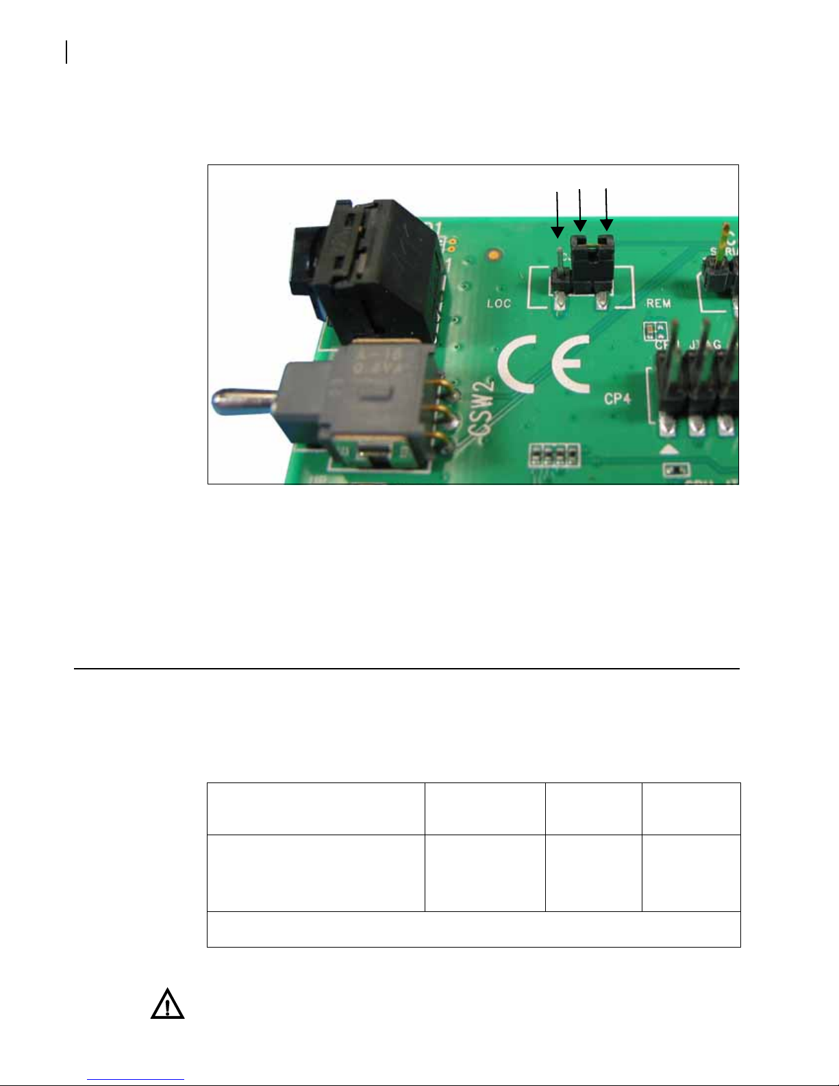
Figure 2-1 Jumper Locations (CD/CDL Version Shown)
Remote/Local jumper
Chapter 2
Installation and Operation
6
Prior to power-up, set the jumper for the correct Remote/Local configuration. Place a
jumper on pins 1and 2to set the module for Remote control, or pins 2and 3to set the
module for Local control.
Figure 2-2 Jumper CJ3/CJS3 for Remote and Local Control
The Local setting locks out external control panels and allows card-edge control only;
remote software applications can monitor, but not control the module. The Remote setting
allows either remote or local (card-edge) configuration, operation, and monitoring.
At the rear of the front module, Jumper CJ2 is factory-set and should not be modified.
Maximum Frame Power Ratings
ACO6800+AES modules operate only in fan-cooled FR6822+QXFE frames, or FR6822+F
frames containing a 6800+ETH module, subject to the limitations shown in Table 2-1.
CAUTION: To maintain proper air flow and internal frame temperature, ensure that
the front panel is closed at all times and that the fan module is fully operational.
Pins: 3 2 1
Table 2-1 Maximum Allowable Frame Power Ratings
Frame Type
Max. Frame
Power
Dissipation
Number of
Usable
Slots*
Max. Power
Dissipation
Per Slot
FR6822+QXFE frame
FR6822+F frame containing a
6800+ETH module (v. 4.8 or
higher)
120W 20 6 W
*Each ACO6800+AES module requires two slots; a frame can accommodate a maximum of ten ACO6800+AES
modules.

ACO6800+AES
Installation and Operation Manual
7
Installing ACO6800+AES Modules
ACO6800+AES products can be installed in an FR6822+QXFE frame, or an FR6822+F frame
containing a 6800+ETH module, except in slots 6 and 14.
When installing both front and rear modules together, ensure that the back module is
installed first before plugging in the front module. During removal, ensure that the front
module is unplugged from the frame first, before removing the rear module. Do not mix
ACO6800+AES front and back modules. -BD, -CD, and -CDL back modules must be
matched with their own front modules.
Any unused loop outputs on the -CDL back should have a 75Ωtermination.
See your Frame Installation and Operation Manual for general information about installing
back modules in a frame.
CAUTION: Before installing this product, read the 6800+Series Safety Instructions
and Standards Manual available on our website, or on the Harris Infrastructure and
Networking Documentation DVD. This safety manual contains important
information about the safe installation and operation of 6800+series products.
Upgrading Module Firmware
This module’s firmware can be updated using CCS Navigator version 4.7 or higher, or the
HTTP software upgrade tool. In order to perform these upgrades, the frame must be
equipped with a 6800+ETH module, version 4.7 or higher. See your frame manual for more
information.
Operating Notes
When setting the control parameters on the ACO6800+AES, note the following:
If you make changes to certain parameters, other related parameters may also be
affected or become disabled. See ACO6800+AES Control Parameters on page 16 for
more information.
When you change a parameter, the effect is immediate. However, the module requires
up to 30 seconds to save the latest change. After 30 seconds, the new settings are
saved and will be restored if the module loses power and must be restarted.
When you set the Factory Recall parameter to Yes, the module takes several seconds
to reset all of the parameters to their default settings.

Chapter 2
Installation and Operation
8
Changing Parameter Settings
For best results, use a software control (serial/local or Ethernet/remote) to aid in viewing,
setting, and confirming parameter values. Follow these steps to change the parameter
settings:
1Rotate the mode select rotary switch (hex switch) to 0.
2Once the hex switch is set to 0, toggle the navigation switch up or down to select a bank.
View the two control LEDs next to the navigation toggle switch to see which bank is
currently selected.
See page 16 to view the various banks, hex switch positions, and corresponding parameter
options and values.
3Rotate the hex switch to the parameter number (1to 9) or letter (Ato F) of the option you
want to set.
4Toggle the navigation switch to select and set the value of the chosen parameter.
5Rotate the hex switch to another parameter number/letter in the current bank, and then
repeat step 4.
or
Rotate the hex switch to the 0position again to select a different bank, and then repeat
steps 3 and 4.
Recalling Default Parameter Settings
See page 16 for all of the parameter settings for the ACO6800+AES modules, including the
original factory defaults. To return this module to its default settings, you can either reset
each parameter individually or do a global recall following this procedure:
1Rotate the hex switch to 0.
2Toggle the navigation switch to the bank number 0.
Use the control LEDs to verify which bank you have selected, or use an available 6800+
software control option (serial/local or Ethernet/remote) to aid in confirming your bank
selection.
3Rotate the hex switch to the global recall parameter F.
4Toggle the navigation switch to On.
Use an available 6800+software control option to aid in viewing, setting, and confirming
the parameter value.
Table 2-2 Selected Bank as Indicated by Control LEDs
Bank
Number LED3LED2LED1LED0
0 Off Off Off Off
1 Off Off Off On

ACO6800+AES
Installation and Operation Manual
9
Changing Parameter Settings Using CCS Software
Before using CCS Navigator to change your module’s parameter settings, you must discover
the module.
Discovering the Module Using CCS Software
To discover your module, your Navigator software must be in Build mode.
1If the Discovery window is not open, click Tools > Discovery in the main menu.
A Discovery window opens, most likely in the bottom left corner of the screen.
2Click Options, and then click Add.
3Enter the IP address of the frame that contains your module, or the frame that contains a
6800+ETH module that provides access to your module.
4Click OK to close the Add Host dialog box, and then click OK again to close the Discovery
Options dialog box.
5Click Start.
This triggers Navigator to run a discovery. When the discovery finishes, Discovery
Completed is displayed in the Discovery pane.
6Click Save to save the results of your discovery to the Discovery folder of the Navigation
pane.
7Switch to Control mode by selecting Operational Mode > Control from the main menu.
8Double-click ACO6800+AES in the Navigation pane.
The Control window opens, displaying the module’s controls.
You can now switch to Control mode by selecting Operational Mode > Control from the
main menu. Double-click ACO6800+AES in the Navigation pane. The Control dialog box
opens, displaying the module’s controls.
Reading Software and Hardware Versions
The current software version of your module can be viewed using an HTTP browser, a
CCS-enabled control panel, or CCS Navigator.
Chapter 2
Installation and Operation
10
Audio Configuration
The ACO6800+AES operates in one of two DA Work Modes:
2x4 mode (dual independent one input/ four output DA)
1x8 mode (one input/ eight output DA)
(-CDL versions are effectively 2x3 and 1x6 because one output in each channel is a
loopthrough.)
When you select either one of the DA Work Modes, the available options change in the
parameter tree.
Switch Settings with the 2X4 Work Mode
To make settings in the 2X4 Work Mode, follow these steps.
1In Audio Configuration, select DA Work Mode > 2X4.
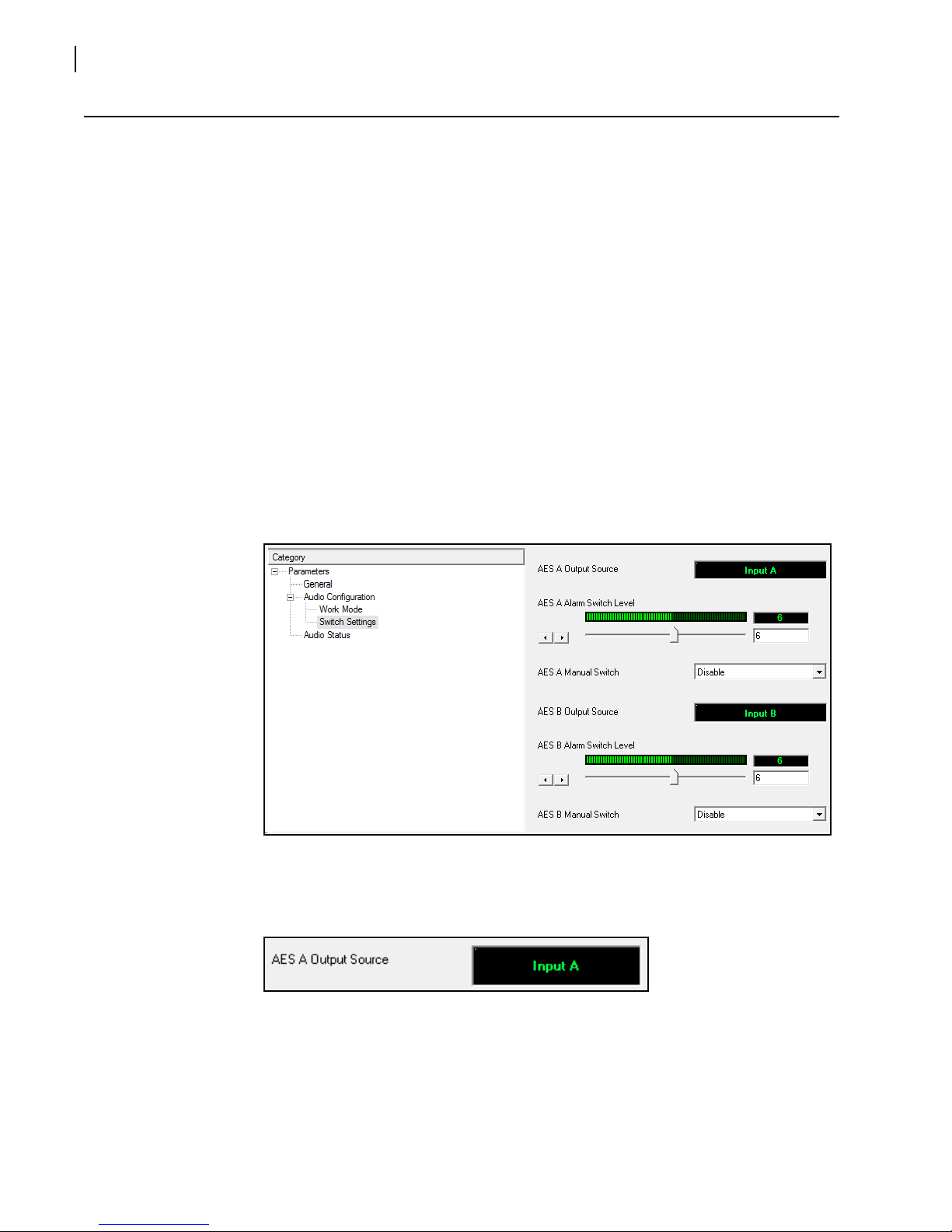
2In Audio Configuration, select Switch Settings.
In CCS Navigator, a sub-page appears as below.
Figure 2-3 2X4 Switch Setting
The AES x Output Source parameter displays the current AES output source.
Figure 2-4 AES x Output Source
3Set the AES x Alarm Switch Level (for details, see AES x Alarm Switch Level on
page 13).

ACO6800+AES
Installation and Operation Manual
11
Figure 2-5 AES x Alarm Switch Level
4Set the option you require for the AES x Manual Switch, which controls the output
source.
Figure 2-6 AES x Manual Switch
Switch Setting with 1X8 Work Mode
To make settings in the 1X8 Work Mode, follow these steps.
1In Audio Configuration, select DA Work Mode >
2In Audio Configuration, select Switch Settings.
In CCS Navigator, a sub-page appears as below.
Figure 2-7 Switch Settings
The AES Output Source parameter displays the current AES output source.
Figure 2-8 AES Output Source
3Set the Alarm Switch Level (for details, see AES x Alarm Switch Level on page 13)
Other manuals for Selenio 6800
2
This manual suits for next models
5
Table of contents
Other Imagine communications Switch manuals

Popular Switch manuals by other brands

Cabletron Systems
Cabletron Systems SmartSwitch 6500 user guide

Kramer
Kramer VS-41H user manual

Linksys
Linksys FENSK05 - EtherFast Network Starter Specifications

Meilhaus Electronic
Meilhaus Electronic ME-USB Iso Instructions for use

Goobay
Goobay 67178 user manual

Vega
Vega VEGASWING 51 operating instructions


