Menu #2 - Sub
Adjustable list, display the address of net mask
Menu #3 - GateWay
Adjustable list, display the gateway address of SNMP
Menu #4 - TRAP1
Adjustable list, display the TRAP1 address of SNMP
Menu #5 - TRAP2
Adjustable list, display the TRAP2 address of SNMP
2.1.3 Menu assistant manual
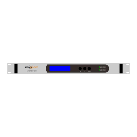
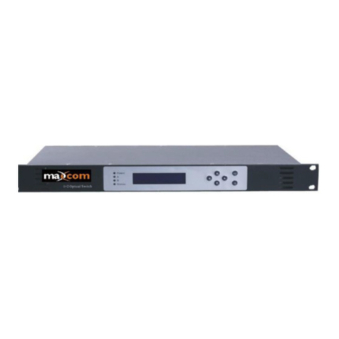
1. Press the right button to display each parameter
show parms
2. Stage 1 menu: Press left button to display previous menu, press the
right button to display next menu, press the UP button to go back to
the main menu, pressing the DOWN button is invalid (not used).
last exit next
3. Stage 2 menu: Press left button to display former menu, press the
right button to display the next menu, press the UP button to go back
the main menu, press DOWN button to set the submenu.
last exit edit next
4. Stage 3 menu: Press left button to display current value minus 1,
press right button for current value plus 1, press UP button to cancel
the setting, press the DOWN button to save and exit the submenu.
dec cancel save inc
Shown with RF ports on front panel for display purposes
When the Switch Mode is selected as “Automatic State”, the input power on main
channel will typically be the one running at a higher RF level and will be the primary
output. If the main input is lower than the switch point power defined, and the input
power on subordinate channel is higher than the switch point power defined, then the
unit should switch the output from the secondary input
When the Switch Mode is selected as “Manual: Input 1 out; Input 2 out”, select the
desired channel output.


