SERIAL CONVERTER
CONV32V03-01T-17183
CONV32
Ver.03
Have this manual in your hands
using the FG Finder app. Serial USB
communication
RS
485
WARNING
BEFORE THE INSTALLATION OF THIS CONVERTER, WE RECOMMEND READING THE FULL INSTRUCTION MANUAL TO PREVENT POSSIBLE DAMAGE TO THE PRODUCT.
PRODUCT INSTALLATION PRECAUTIONS:
- Ensure the instrument has adequate ventilation, avoiding installation on control panels containing devices that could cause it to operate outside its specified temperature range;
- Install the product away from sources that may generate electromagnetic noise, such as: motors, contactors, relays, electrovalves, etc;
AUTHORIZED SERVICES:
The installation and maintenance of the product must be performed only by qualifed personnel;
ACCESSORIES:
Use only Full Gauge Controls original accessories. If you have any questions, please contact our technical support.
THROUGH CONTINUOUS DEVELOPMENT, FULL GAUGE CONTROLS RESERVES THE RIGHT TO CHANGE THE INFORMATION CONTAINED IN THIS MANUAL AT ANY TIME, WITHOUT PRIOR NOTICE.
1. DESCRIPTION
CONV32 Interface allows Full Gauge controllers, equipped with serial communication, to be connected to a computer that has a USB serial communications port.
The Interface then takes care of the transformation of the voltage levels used by the computer to the RS-485 voltage levels used by the controllers.
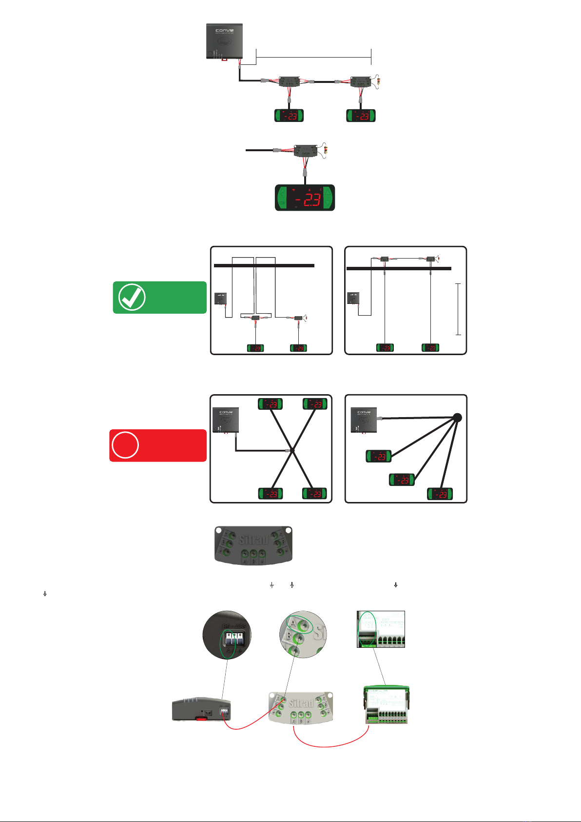
Full Gauge uses a RS-485 network to make the communication between the controllers and Sitrad software more reliable. The communication uses two wires (A and B), allowing the performance of
Half-Duplex communication, where the computer is the master and the controllers are slaves.
2. TECHNICAL SPECIFICATIONS
Operating temperature 0 to 50ºC / 32 to 122ºF
Operating humidity 10 to 90% UR (without condensation)
32
Number of instruments supported per converter in the RS-485 network
Product dimensions
Maximum converter power consumption
91,0 x 91,1 x 37,1 mm (WxHxD)
70 mA
IMPORTANT:
For a correct and robust installation of the RS-485 network, see item 6 -
Interconnecting the controllers and CONV32.
- The extension of the RS-485 network must not exceed 1000 meters.
- Always use a shielded USB cable with a maximum length of 6 ft (1.8 meters) and
certified by USB.org.
!
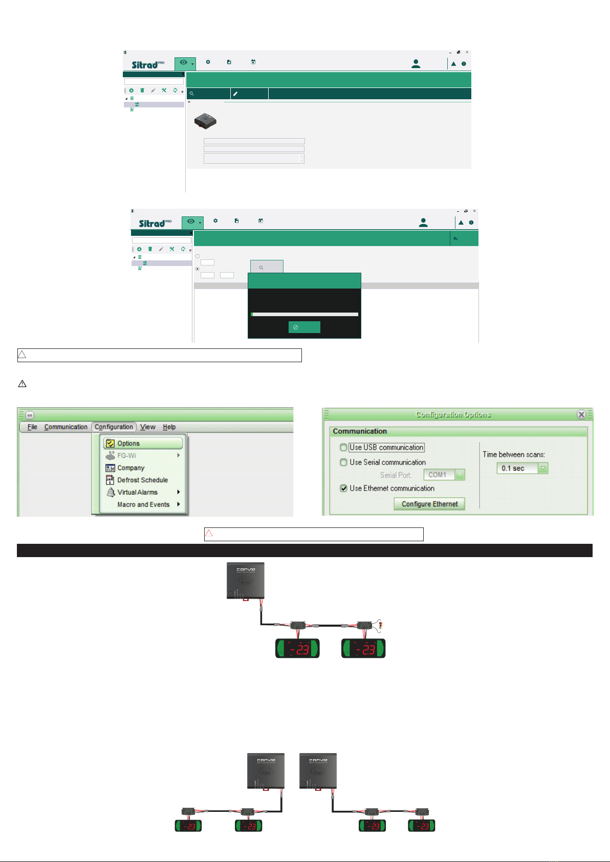
3. INSTALLATION
1 - The CONV32 does not require the installation of any driver in Windows;
2 - This conversion interface uses a HID (Human Interface Device) communication;
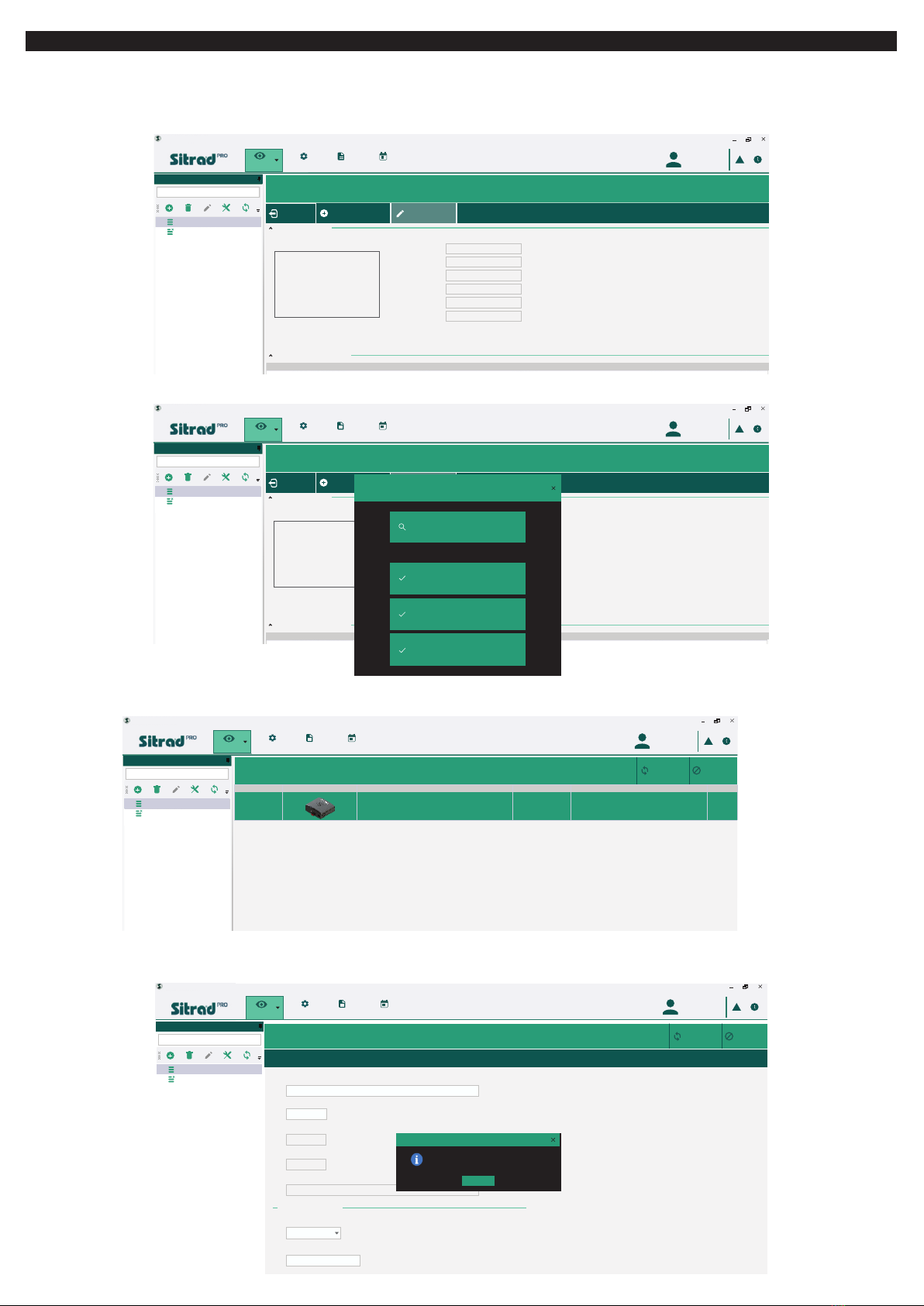
3 - Check Item 5 - Installation and operation to register the converter in Sitrad software.
Controller
RS-485
MT-530 super MT-530 super
CONV32
Computer
USB Cable
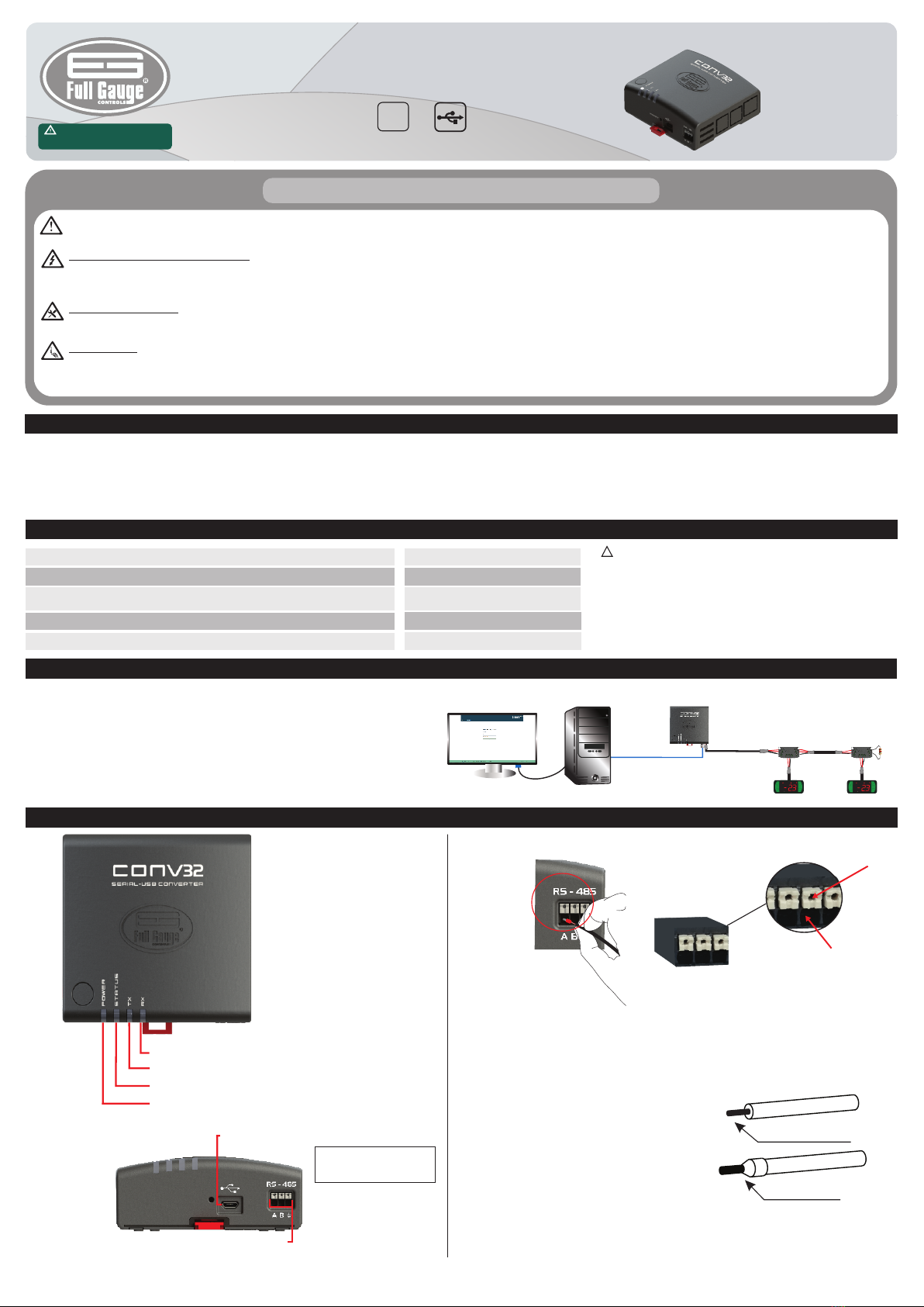
4. INDICATORS
Power LED - Power indication LED
RS-485 network transmission indication LED
RS-485 network reception indication LED
Status LED - Connection status indication LED
RS-485 network communication input
USB connection
4.1. CONNECTION SYSTEM (QUICK CONNECTION): PUSH IN
CONNECTION:
- Hold the wire close to its end and insert it in
the desired input.
- If required, press the button to help make
the connection.
DISCONNECTION:
- To disconnect the wire, press the white
button and remove it.
NOTE:
- For the Push In connectors, the maximum
wire gauge is 1.5mm².
- The wires must be coated with solder or use
Rocket Pin terminals with a 0.75mm²
maximum gauge.
The wire must be stripped in
5mm and solder-coated.
Rocket Pin Terminal
- Sitrad Pro allows installing more than one CONV32 Interface version 03 or
higher.
Note: Use the cable supplied with
the converter to connect it to the
computer.
WIRE INPUT
BUTTON