Imagine Selenio SEL-1DEC1 User manual

SELENIO™ SEL‐1DEC1/SEL‐1DEC2
8‐Bit/10‐Bit Universal Decoders
Version 7.0
September 2014
Installation and Operation Manual

SELENIO™ SEL‐1DEC1/SEL‐1DEC2 8‐Bit/10‐Bit Universal Decoders Installation and Operation Manual
© 2014 Imagine Communications Corp. Proprietary and Confidential. Version 7.0 | Page 2
Publication Information
© 2014 Imagine Communications Corp.
Proprietary and Confidential.
Imagine Communications considers this document and its contents to be proprietary and confidential.
Except for making a reasonable number of copies for your own internal use, you may not reproduce this
publication, or any part thereof, in any form, by any method, for any purpose, or in any language other
than English without the written consent of Imagine Communications. All others uses are illegal.
This publication is designed to assist in the use of the product as it exists on the date of publication of
this manual, and may not reflect the product at the current time or an unknown time in the future. This
publication does not in any way warrant description accuracy or guarantee the use for the product to
which it refers. Imagine Communications reserves the right, without notice to make such changes in
equipment, design, specifications, components, or documentation as progress may warrant to improve
the performance of the product.
Trademarks
SelenioTM is a trademark of Imagine Communications or its subsidiaries. Microsoft® and Windows®
are registered trademarks of Microsoft Corporation. HD‐BNC is a trademark of Amphenol Corporation.
Manufactured under license from Dolby Laboratories. Dolby and the double‐D symbol are registered
trademarks of Dolby Laboratories. All other trademarks and trade names are the property of their
respective companies.
Contact Information
Imagine Communications has office locations around the world. For domestic and international location
and contact information, visit our Contact page
(http://www.imaginecommunications.com/company/contact‐us.aspx).
Support Contact Information
For domestic and international support contact information see:
Support Contacts (http://www.imaginecommunications.com/services/customer‐care.aspx)
eCustomer Portal (http://support.imaginecommunications.com)
Academy Training (http://www.imaginecommunicationsacademy.com)

SELENIO™ SEL‐1DEC1/SEL‐1DEC2
Installation and Operation Manual Contents
© 2014 Imagine Communications Corp. Proprietary and Confidential. Version 7.0 | Page 3
Contents
Product Description ............................................................................................... 7
Main Features........................................................................................................................................... 7
Module Types ........................................................................................................ 9
Front Module....................................................................................................... 11
Back Modules ...................................................................................................... 12
Pinouts....................................................................................................................................................13
Signal Flow........................................................................................................... 14
Installing Selenio Modules in an MCP3 Frame ..................................................... 15
Removing Selenio Modules from an MCP3 Frame ............................................... 16
Front Module..........................................................................................................................................16
Back Module...........................................................................................................................................17
Powering Up a Module ........................................................................................ 17
Upgrading Module Firmware ............................................................................... 18
Upgrade Failure Instructions ..................................................................................................................18
Accessing MIBs .................................................................................................... 19
Examples:................................................................................................................................................19
IP LAN .................................................................................................................. 20
General ................................................................................................................................................... 20
Data Ethernet Protection ................................................................................................................... 20
Primary and Secondary Data Ethernet ...................................................................................................20
Transport Stream Input........................................................................................ 20
General ................................................................................................................................................... 20
Primary Source and Alternate Source ................................................................................................ 20
Primary and Alternate Transport Stream Present, Primary and Alternate Transport Stream Rate .. 21

SELENIO™ SEL‐1DEC1/SEL‐1DEC2
Installation and Operation Manual Contents
© 2014 Imagine Communications Corp. Proprietary and Confidential. Version 7.0 | Page 4
Source Selection and Switching Delay................................................................................................21
IP Jitter Buffer Delay........................................................................................................................... 21
IP Seamless Protection Buffer Delay ..................................................................................................21
FEC Discard .........................................................................................................................................22
Transport Stream Errors and Errored Seconds ..................................................................................22
Primary and Secondary IP.......................................................................................................................22
Status ASI................................................................................................................................................22
Status IP.................................................................................................................................................. 22
Transport Stream Demux..................................................................................... 23
General ................................................................................................................................................... 23
Input Programs Table ......................................................................................................................... 23
Audio Streams Table .......................................................................................................................... 24
Audio x Selector and Audio x Stream/PID/Language.........................................................................24
Serial 1 and Serial 2 Selector ..............................................................................................................25
DVB Subtitle 1 to 4 Selector ............................................................................................................... 25
VBI Selector and VBI Channel Set....................................................................................................... 25
BISS ......................................................................................................................................................... 25
Clear Session Word Mode .................................................................................................................. 25
Encrypted Session Word ....................................................................................................................25
Subtitle Forwarding ................................................................................................................................26
Status...................................................................................................................................................... 26
Video Decompression .......................................................................................... 26
General ................................................................................................................................................... 26
Output Format Set.............................................................................................................................. 26
Output Aspect Ratio...........................................................................................................................26
No Input Action .................................................................................................................................. 27
Clipping...............................................................................................................................................27
Video Status............................................................................................................................................ 27
Audio Decompression.......................................................................................... 28
General ................................................................................................................................................... 28
Mode .................................................................................................................................................. 28
Delay................................................................................................................................................... 29
Gain ....................................................................................................................................................30
Passthrough........................................................................................................................................30
Dolby Digital Control Audio x ................................................................................................................. 30
Operation Mode................................................................................................................................. 30
High and Low Dynamic Range Scale...................................................................................................30

SELENIO™ SEL‐1DEC1/SEL‐1DEC2
Installation and Operation Manual Contents
© 2014 Imagine Communications Corp. Proprietary and Confidential. Version 7.0 | Page 5
Apply RF Mode Gain...........................................................................................................................31
Stereo Down Mix Mode .....................................................................................................................31
Dual Mono Playback........................................................................................................................... 31
Status Audio x.........................................................................................................................................31
Metadata Audio x ...................................................................................................................................32
Audio Output Routing.......................................................................................... 33
General ................................................................................................................................................... 33
VANC Processing.................................................................................................. 33
HD‐SDI to HD‐SDI....................................................................................................................................33
HD‐SDI to SD‐SDI..................................................................................................................................... 34
SD‐SDI to HD‐SDI.....................................................................................................................................34
General ................................................................................................................................................... 36
RDD‐11 and SMPTE‐2038 ...................................................................................................................36
SMPTE‐2031 Line................................................................................................................................ 36
SCTE‐104 Line .....................................................................................................................................37
Other Line Selections..........................................................................................................................37
Audio Metadata..................................................................................................................................37
Video Index.........................................................................................................................................38
VANC Status............................................................................................................................................38
VBI Processing...................................................................................................... 39
General ................................................................................................................................................... 39
VBI Status................................................................................................................................................39
GPI ....................................................................................................................... 39
General ...................................................................................................................................................
39
GPI Out 1 Set to GPI Out 4 Set............................................................................................................39
GPI Status ...............................................................................................................................................39
GPI Out 1 to GPI Out 4 Status............................................................................................................. 39
Custom GPI .............................................................................................................................................40
Writing Custom GPI Scripts ................................................................................................................ 40
GPI Output Example ........................................................................................................................... 40
Sample Use Cases............................................................................................................................... 41
Serial.................................................................................................................... 41
Serial 1 and Serial 2 ................................................................................................................................ 41
Serial x Function .................................................................................................................................41
Baud Rate ........................................................................................................................................... 42
Serial x Type Select............................................................................................................................. 42

SELENIO™ SEL‐1DEC1/SEL‐1DEC2
Installation and Operation Manual Contents
© 2014 Imagine Communications Corp. Proprietary and Confidential. Version 7.0 | Page 6
External Data UDP Unicast and Multicast .......................................................................................... 42
UDP Data Status .................................................................................................................................42
Miscellaneous...................................................................................................... 43
General ................................................................................................................................................... 43
Parameter Control Script........................................................................................................................ 43
Writing the Parameter Control Script ................................................................................................ 44
Support Replacement of DEC1 by DEC2.................................................................................................45
Alarms.................................................................................................................. 45
Laser Safety for Fiber Optic Back Modules........................................................... 47
Precautions for Enclosed Systems.......................................................................................................... 47
Precautions for Unenclosed Systems ..................................................................................................... 48
Label .................................................................................................................... 49
Inspecting and Cleaning Fiber Optic Connections ................................................ 49
Important Points..................................................................................................................................... 50
Inspection and Cleaning Procedure........................................................................................................ 51
Inspection...........................................................................................................................................51
Dry Cleaning .......................................................................................................................................51
Wet Cleaning ......................................................................................................................................51
Specifications....................................................................................................... 53
AES Output Specifications ...................................................................................................................... 53
ASI Input Specifications ..........................................................................................................................53
SDI Output Specifications ....................................................................................................................... 54
Power Consumption...............................................................................................................................58
Index.................................................................................................................... 59

SELENIO™ SEL‐1DEC1/SEL‐1DEC2
Installation and Operation Manual Product Description
© 2014 Imagine Communications Corp. Proprietary and Confidential. Version 7.0 | Page 7
Product Description
The Selenio SEL‐1DEC1 and SEL‐1DEC2 modules are multi‐format video decoders that handle both H.264
and MPEG‐2 video streams and their commonly associated audio and data streams.
The SEL‐1DEC1 and SEL‐1DEC2 support all popular digital video formats from SD‐SDI through 3G HD‐SDI
video*, and up to eight channels of MPEG‐1 layer 2, Dolby® Digital (AC‐3), Dolby Digital Plus, AAC‐LC, HE‐
AAC, Dolby E, or SMPTE 302 (uncompressed) audio. Audio outputs are provided as unbalanced AES or
embedded audio. In addition, the SEL‐1DEC1 and SEL‐1DEC2 re‐insert VANC and VBI data into the video
signal.
*3G HD‐SDI is not currently supported by the 10‐bit SEL‐1DEC2 module
Main Features
The SEL‐1DEC1 and SEL‐1DEC2 modules offer the following main features:
•Support for a single‐input transport stream from any of the following sources:
•IP using UDP or RTP protocols and SMPTE‐2022 error protection
•IP using RTP protocol and Seamless Protection (see IP Seamless Protection Buffer Delay (on page
21))
•DVB‐ASI from the rear I/O interface
•Internal connection from other application modules in the frame
•Support for the decoding of the following constant bit rate streams (CXN, ASI, and ExtIP sources) and
variable bit rate streams (CXN and ASI sources):
•H.264 High Profile @ up to L4.2 (62.5 Mb/s max)
•H.264 Main Profile @ up to L4.2
•H.264 Baseline Profile @ up to L1.3
•H.264 High‐10 Intra and H.264 High‐10 (SEL‐1DEC2)
•MPEG‐2 422 Profile @ up to High Level (65 Mb/s max)
•MPEG‐2 restricted to Main Profile @ up to High Level
•Support for any legal horizontal resolution
•Support for any of the following output video formats:
•1080p/59, 1080p/50 ‐ SMPTE424/425 Level A 3G‐SDI
•1080i/29, 1080i/25 ‐ SMPTE292
•720p/59, 720p/50 ‐ SMPTE292
•480i/29 ‐ SMPTE259
•576i/25 ‐ SMPTE259
•Horizontal scaling for streams with reduced horizontal resolution
•Crossconversion of the following standards:*

SELENIO™ SEL‐1DEC1/SEL‐1DEC2
Installation and Operation Manual Product Description
© 2014 Imagine Communications Corp.Proprietary and Confidential. Version 7.0 | Page 8
•SD‐SDI (NTSC or PAL) to HD‐SDI (1080I, 720p) at the same frame rate as the source, maintaining
aspect ratio by letter/pillar boxing as necessary.
•HD‐to‐SD‐SDI at the same frame rate as the source, maintaining aspect ratio by letter/pillar
boxing as necessary
•HD‐to‐HD‐SDI (1080I to/from 720p) at the same frame rate as the source (when HD/SD‐SDI is
configured and AFD is present, AFD can further refine scaling)
•Mobile streams (vertical resolution below 480) displayed as either full screen with letter/pillar
boxing as necessary, or centered with no vertical scaling
•3G HD‐SDI to 1080i or 720p
•Decoded video can be synchronized to the clock recovered from the input bit stream, or
genlocked to the frame reference
•Audio decoding features, including:
•Support for up to 8 audio streams
•Support for MPEG 1 Layer 2, Dolby Digital (AC‐3), Dolby Digital Plus, AAC‐LC, HE‐AAC including
SBR and Parametric Stereo, SMPTE‐302 (AES‐3 over MPEG), and Dolby E
•Support for SMPTE 337 formatted pass‐through of Dolby Digital, Dolby Digital Plus and Dolby E
encoded streams
•VANC insertion features, including:
•VANC pass‐through
•EIA‐608/708 closed captioning
•AFD
•DVITC timecode
•OP‐47 teletext
•KLV
•SMPTE 2020 audio metadata
•SCTE 104 messages
•SMPTE 2031 (VBI over VANC)
•Synthesized VBI insertion features, including the following:
•EIA‐608 closed captioning
•SMPTE timecode
•AMOL‐48 or AMOL‐98
•ETSI EN 301 775 signals: Closed Captions, WSS, VPS, Monochrome, and WST
•KLV ES
•Video Index
•Custom GPI and parameter control scripts
•Configurable SMPTE‐2022‐2 support
•Serial data output that is configurable to the output of serial transport data or audio metadata
•Rear I/O connections of the following:
•High‐Density (HD‐BNCTM) ASI inputs (1x for DEC1 and 2x for DEC2)
•2x HD‐BNC SDI outputs
•2x HD‐BNC ASI loop‐throughs

SELENIO™ SEL‐1DEC1/SEL‐1DEC2
Installation and Operation Manual Module Types
© 2014 Imagine Communications Corp. Proprietary and Confidential. Version 7.0 | Page 9
•8 x HD‐BNC Primary AES Audio Outputs
•2x serial ports configurable as RS‐232 or RS‐422
•GPI input and outputs
*The SEL‐1DEC1 and SEL‐1DEC2 provide utility‐grade format conversion. For professional broadcast‐
quality post‐processing, the SEL‐1XD1 and SEL‐2XD1 (for conversion), and SEL‐1FS1 and SEL‐2FS1 (for
frame sync) are recommended.
Module Types
Table 1: Module Descriptions
Product Description
SEL‐1DEC1
SEL‐1DEC1‐EES Multi‐Standard 8‐bit Decoder hardware;
includes single channel of video and four stereo pairs of audio, single back module
with (High‐Density) HD‐BNC connectors for ASI input/outputs, SDI video outputs,
AES (unbalanced) outputs, GPI inputs/outputs and serial data (software model key
must be selected to enable functions)
SEL‐1DEC1‐EOS Multi‐Standard 8‐bit Decoder hardware;
includes single channel of video and four stereo pairs of audio, single back module
with (High‐Density) HD‐BNC connectors for ASI input, dual SFP output (ordered
separately), SDI video out, AES out (unbalanced), GPI in/out and serial data
(software model key must be selected to enable functions)
SEL‐1DEC2
SEL‐1DEC2‐EES Same as SEL‐1DEC1‐EES, with 8‐bit and 10‐bit capability
SEL‐1DEC2‐EOS Same as SEL‐1DEC1‐EOS, with 8‐bit and 10‐bit capability
Table 2: Module Types
Product Description
SEL‐1DEC1
SEL‐SK‐DE‐PRO MPEG‐2 4:2:0 and 4:2:2 video profiles, H.264 4:2:0 up to 1080p 3G support
SEL‐SK‐DE‐STD MPEG‐2/H.264 4:2:0 video profile
SEL‐1DEC2
SEL‐SK‐DE2‐BSC Same as SEL‐SK‐DE‐PRO, but without the MPEG‐2 422 video decoder
SEL‐SK‐DE2‐PRO All features of SEL‐SK‐DE2‐STD plus 10‐bit decode
SEL‐SK‐DE2‐STD All features of SEL‐SK‐DE2‐BSC plus 4:2:2 decode

SELENIO™ SEL‐1DEC1/SEL‐1DEC2
Installation and Operation Manual Module Types
© 2014 Imagine Communications Corp. Proprietary and Confidential. Version 7.0 | Page 10
Table 3: Softkey Options
Product Description
SEL‐1DEC1
SELOPT‐SK‐DE‐AUD4 Software keyed option for additional 4 stereo pairs of audio available on‐board
SELOPT‐SK‐DE‐BISS Software keyed option for DVB Fixed‐key Scrambling modes BISS‐1
SELOPT‐SK‐DE‐DDD
Software keyed option for support of Dolby Digital and Dolby Digital Plus stereo or
5.1 decoding (5.1 decoding uses 3 of the available 4 or 8 stereo pairs)
SELOPT‐SK‐DE‐DED Software keyed option for SEL‐1DEC1, providing support for Dolby E (uses 4 of the
available 4 or 8 stereo pairs)
SELOPT‐SK‐DE‐S302 Software keyed option to support for up to four stereo pairs of SMPTE‐302 pass‐
through audio (eight pairs when combined with SELOPT‐SK‐DE‐AUD4)
SEL‐1DEC2
SELOPT‐SK‐D2‐AUD4 Software keyed option for additional 4 stereo pairs of audio available on‐board
SELOPT‐SK‐D2‐BISS Software keyed option for DVB Fixed‐key Scrambling modes BISS‐1
SELOPT‐SK‐D2‐DDD Software keyed option for support of Dolby Digital and Dolby Digital Plus stereo or
5.1 decoding
(5.1 decoding uses 3 of the available 4 or 8 stereo pairs)
SELOPT‐SK‐D2‐DED Software keyed option for SEL‐1DEC1, providing support for Dolby E (uses 4 of the
available 4 or 8 stereo pairs)
SELOPT‐SK‐D2‐S302 Software keyed option to support for up to four stereo pairs of SMPTE‐302 pass‐
through audio (eight pairs when combined with SELOPT‐SK‐DE‐AUD4)
SELOPT‐SK‐D2‐HITL Software keyed Seamless Switching option
Table 4: SFP Transmitter Options
Product Quantity Description
OP+SFP+TT+13+13 2 1310 nm and 1310 nm wavelength transmitter with pathological
support for baseband video
•OP+SFP+TT+27+29
•OP+SFP+TT+31+33
•OP+SFP+TT+35+37
•OP+SFP+TT+43+45
•OP+SFP+TT+47+49
•OP+SFP+TT+51+53
•OP+SFP+TT+55+57
•OP+SFP+TT+59+61
2 Transmitter with pathological support for baseband video in the
following wavelength pairs:
•1270 and 1290 nm
•1310 and 1330 nm
•1350 and 1370 nm
•1430 and 1450 nm
•1470 and 1490 nm
•1510 and 1530 nm
•1550 and 1570 nm
•1590 and 1610 nm

SELENIO™ SEL‐1DEC1/SEL‐1DEC2
Installation and Operation Manual Front Module
© 2014 Imagine Communications Corp. Proprietary and Confidential. Version 7.0 | Page 11
Front Module
Figure 1: Front Module (SEL‐1DEC1 Shown)
SELENIO™ SEL‐1DEC1/SEL‐1DEC2
Installation and Operation Manual Back Modules
© 2014 Imagine Communications Corp. Proprietary and Confidential. Version 7.0 | Page 12
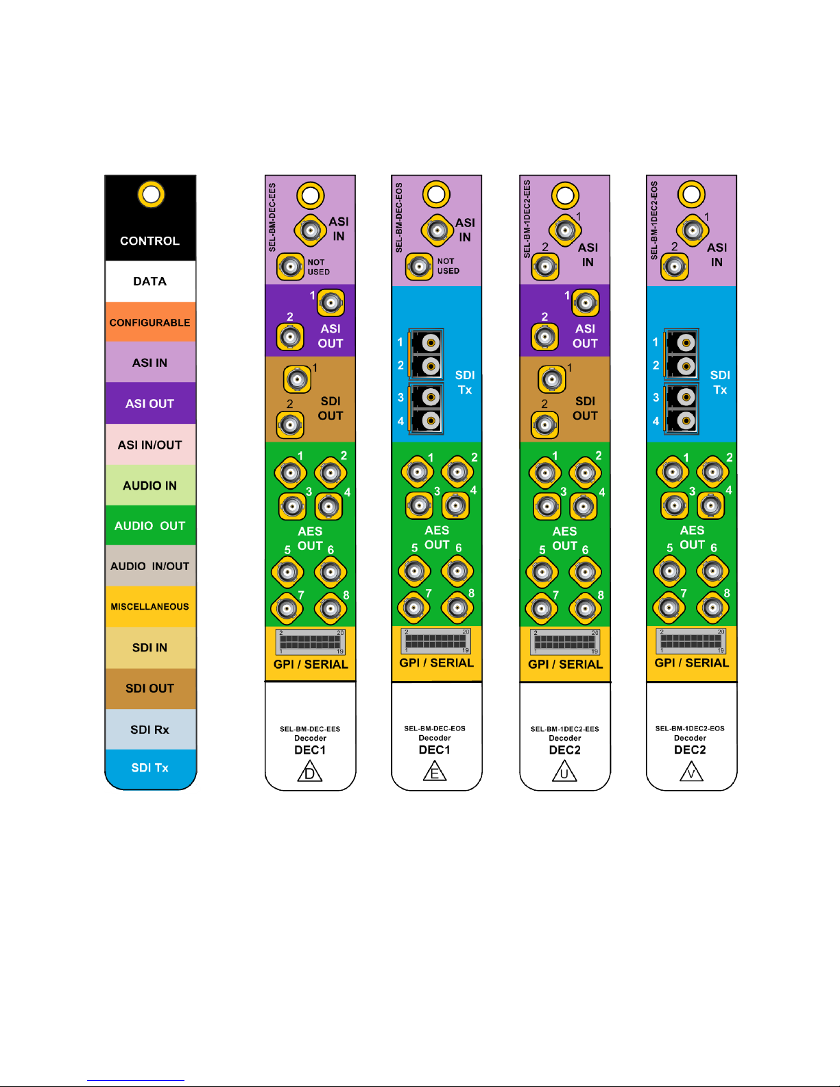
Back Modules
Figure 2: Selenio Color Scheme and Decoder Back Modules

SELENIO™ SEL‐1DEC1/SEL‐1DEC2
Installation and Operation Manual Back Modules
© 2014 Imagine Communications Corp. Proprietary and Confidential. Version 7.0 | Page 13
Pinouts
Figure 3: GPI/Serial Connector Pinouts on the Back Module
Table 5: GPI/Serial Pinouts
Pin Function
1 GPI Out 1 (future use)
2 GPI Out 2 (future use)
3 GPI Out 3 (future use)
4 GPI Out 4 (future use)
5 GPI In 1 (not in use)
6 GPI In 2 (not in use)
7 GPI In 3 (not in use)
8 GPI In 4 (not in use)
9 D‐Ground
10 D‐Ground
11 RS‐422 Port 2 Rx+
12 RS‐422 Port 2 Rx‐ (RS‐232 Port 2 Rx)
13 RS‐422 Port 2 Tx+
14 RS‐422 Port 2 TX‐ (RS‐232 Port 2 Tx)
15 D‐Ground
16 D‐Ground
17 RS‐422Port 1 Rx+
18 RS‐422 Port 1 Rx‐ (RS‐232 Port 1 Rx)
19 RS‐422Port 1 Tx+
20 RS‐422 Port 1 Tx‐ (RS‐232 Port 1 Tx)
SELENIO™ SEL‐1DEC1/SEL‐1DEC2
Installation and Operation Manual Signal Flow
© 2014 Imagine Communications Corp. Proprietary and Confidential. Version 7.0 | Page 14
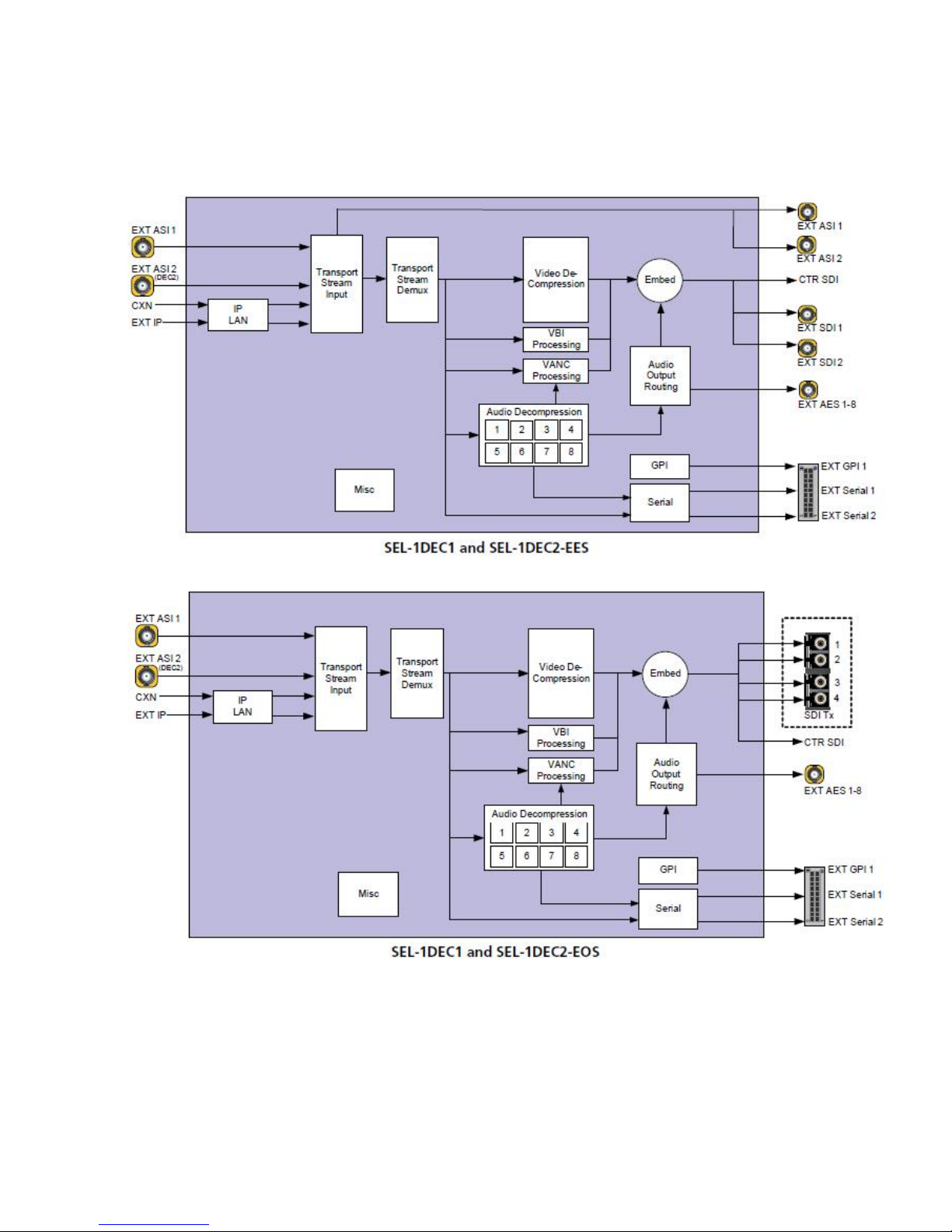
Signal Flow
Figure 4: Decoder Signal Flow

SELENIO™ SEL‐1DEC1/SEL‐1DEC2
Installation and Operation Manual Installing Selenio Modules in an MCP3 Frame
© 2014 Imagine Communications Corp. Proprietary and Confidential. Version 7.0 | Page 15
Installing Selenio Modules in an
MCP3 Frame
Where space allows, Selenio DEC1 and DEC2 modules can be installed in any MCP3 frame. Additionally,
Selenio DEC2 modules are available as part of pre‐configured MCP1 packages.
You can insert a Selenio module into an MCP3 frame with the power supply turned on or off. Follow this
procedure:
1. Remove a blank back module from the frame, saving the blank back modules and their captive
screws for future configurations.
2. Attach the new back module to the empty slot, using the mounting screws provided.
Align the back module’s pin into the guide hole, and ensure that the EMI gaskets separating the back
modules remain in place during the installation. The EMI gaskets fit tightly. To ease the installation
of back modules, gradually press each back module into place from the left side to the right side.
Figure 5: Installing Back Modules
3. Apply labels to the back module, if these are supplied separately.

SELENIO™ SEL‐1DEC1/SEL‐1DEC2
Installation and Operation Manual Removing Selenio Modules from an MCP3 Frame
© 2014 Imagine Communications Corp. Proprietary and Confidential. Version 7.0 | Page 16
4. Print out this page and write down the placement of the back modules in the diagram below (back
modules appear on the reverse side when viewed from the front).
Figure 6: Writing Space for Identifying Back Modules
CAUTION:
Do not mix and match back and front modules. The front module must mate with a back module
of the same product.
5. Open the front panel and then slide the correct front modules into the slots that match the back
modules.
Note: It may be necessary to rotate the front support post to allow unrestricted access to the
targeted slot. Ensure that the white extractor handle is at the top of the module, facing
outward, as the module is inserted.
6. Push the module until it seats properly, ensuring the edge of the module is flush with the edge of
the module guides, and the square extractor handle clicks into its slot.
7. Install the remaining back and front modules, make all of the necessary rear connections, and then
close the front panel.
CAUTION:
To prevent overheating during frame operation, keep the front panel closed and all back module
slots covered.
Removing Selenio Modules from an
MCP3 Frame
Front Module
To remove a front module from a Selenio frame, follow this procedure:
1. Open the front panel.
2. Grasp the extractor handle on the module, pulling down slightly.

SELENIO™ SEL‐1DEC1/SEL‐1DEC2
Installation and Operation Manual Powering Up a Module
© 2014 Imagine Communications Corp. Proprietary and Confidential. Version 7.0 | Page 17
3. Using the handle, slide the module out of its slot.
Figure 7: Removing a Front Module
4. Close the front panel to ensure proper frame ventilation.
Back Module
To remove a back module from a Selenio frame, you must first remove the front module. Then unscrew
the back module, and pull it straight out. Cover the opening with a blank back module to ensure proper
frame ventilation.
Powering Up a Module
The SEL‐1DEC1 and SEL‐1DEC2 modules are ready for use when their parameters appear in the Selenio
UI. The Maximum power consumption of an SEL‐1DEC1 or SEL‐1DEC2 module is 40W. Selenio modules
are automatically powered up when they are inserted into a live (powered up) frame, and whenever the
frame is powered up.

SELENIO™ SEL‐1DEC1/SEL‐1DEC2
Installation and Operation Manual Upgrading Module Firmware
© 2014 Imagine Communications Corp. Proprietary and Confidential. Version 7.0 | Page 18
Upgrading Module Firmware
All module firmware upgrades are activated in the frame controller section of the Selenio user interface.
Follow this path to find the appropriate parameters: Configuration > Frame Controller > Configuration
tab > Upgrade Firmware.
See the Selenio frame manual for information on how to upgrade module firmware.
In the unlikely event of an upgrade failure, use the Upgrade Failure Instructions of this manual.
Upgrade Failure Instructions
The SEL‐1DEC1 and SEL‐1DEC2 modules include one user‐configurable DIP switch array (SW2), located at
the card edge next to the extractor. In normal operation, all four switches are in the Off position. In the
unlikely event of corrupted software, you may need to temporarily change the setting of Switch 1 for
the failsafe mode override. You would be alerted to this problem if a System Recovery Upgrade
Required fault was triggered after an upgrade, and the module had finished rebooting.
If a System Recovery Upgrade Required fault is triggered, you should first try using the alternate
firmware (see Activating Alternate Firmware in the Selenio frame manual) and then attempt the
upgrade again. If this second attempt fails, follow these steps to activate the failsafe mode:
1. Remove the module from the frame and then push Switch 1 to the On position (see Figure ).
Figure 8: DIP Switch Setting for Failsafe Mode
2. Reinsert the module.
3. Install the new module software using the Selenio user interface.

SELENIO™ SEL‐1DEC1/SEL‐1DEC2
Installation and Operation Manual Accessing MIBs
© 2014 Imagine Communications Corp. Proprietary and Confidential. Version 7.0 | Page 19
4. Remove the module, and then return Switch 1 to the Off position.
5. Reinsert the module.
The module is now running the new software.
Accessing MIBs
MIB files for all modules can be downloaded directly from any Selenio frame. MIBs are generated on a
per‐device basis. For example, if there are seven SEL‐1DEC1 modules in a frame, only one of the seven 7
MIBs is required, assuming all of the modules are using the same version of software. If the frame
includes multiple modules of the same type, but different software versions, the module with the latest
version should be used to generate the MIB.
If an older MIB is used with newer firmware (for example, an older version of firmware was used instead
of the latest firmware), the new parameters added to the new version will not be available on the MIB,
and thus, will not be accessible via the MIB.
Before downloading module MIBs, you must first download the InfrastructureNetwork.mib file. Copy
the following into a browser to access the InfrastructureNetwork.mib:
http://<IP address>/InfrastructureNetwork.mib
<IP address> is that of the primary controller in the frame
Once any MIB file is downloaded from the frame, you should rename it immediately to prevent
overwriting.
To download a specific module MIB file, copy this line into a browser:
http://<IP address>/mib/slot<slot#>/snmp.mib
<IP address> is that of the primary controller in the frame
<slot#> is the slot in the frame, as seen from the front
Examples:
http://137.237.173.15/mib/slot0/snmp.mib
Accesses the controller MIB from frame 137.237.173.15.
http://137.237.173.15/mib/slot7/snmp.mib
Accesses the MIB for slot 7from 137.237.173.15

SELENIO™ SEL‐1DEC1/SEL‐1DEC2
Installation and Operation Manual IP LAN
© 2014 Imagine Communications Corp. Proprietary and Confidential. Version 7.0 | Page 20
IP LAN
The SEL‐1DEC1 and SEL‐1DEC2 IP LANs communicate with external IP networks via the Data ports on the
primary and secondary frame controller. If your decoder will use data Ethernet from external sources,
you will need to set the Primary and Secondary IP addresses for the decoder; these IP addresses will be
unique to this decoder module.
When configuring the decoder via the Block Diagram View of the GUI, the following parameters are
accessed via the block labeled IP LAN. When configuring the decoder via the All (tree) View of the GUI,
the following parameters are accessed via the Control > IP LAN branch of the tree.
General
Data Ethernet Protection
Use this parameter to specify whether the Primary or Secondary Ethernet interface should be used for
IP input or alternately, select Automatic protection switching. If enabled, Seamless Protection can be
selected using the Data Ethernet Protection drop down menu.
Primary and Secondary Data Ethernet
Use these controls to set the Primary and Secondary IP Address, IP Mask, IP Gateway, and VLAN ID,
and to observe the Primary/Secondary Data Eth MAC addresses. Press Apply to enable the changes.
There are no default IP addresses for the decoder module.
Transport Stream Input
General
Primary Source and Alternate Source
The transport stream input signal can originate from external ASI connections (EXT ASI 1 and—for DEC2
only, EXT ASI 2), an internal IP network (CXN) or an external Ethernet (Ext IP). To enable the external
Ethernet as a source, you must enter the Primary or Secondary IP address. The Alternate Source
provides a backup in the event of a loss of signal from the Primary Source. (To provide an alternate
source for IP inputs, see Data Ethernet Protection (on page 20) above.) In Seamless Protection mode,
the two IP stream addresses are entered in the Primary and Secondary IP address fields.
This manual suits for next models
1
Table of contents
Other Imagine Media Converter manuals


