IMCA Mini RadaScan User manual

Mini RadaScan Microwave
Radar Sensor for Dynamic
Positioning Operations
IMCA M 229
October 2015

The International Marine Contractors Association
(IMCA) is the international trade association
representing offshore, marine and underwater
engineering companies.
IMCA promotes improvements in quality, health, safety,
environmental and technical standards through the publication of
information notes, codes of practice and by other appropriate
means.
Members are self-regulating through the adoption of IMCA
guidelines as appropriate. They commit to act as responsible
members by following relevant guidelines and being willing to be
audited against compliance with them by their clients.
There are two core activities that relate to all members:
Competence & Training
Safety, Environment & Legislation
The Association is organised through four distinct divisions, each
covering a specific area of members’ interests: Diving, Marine,
Offshore Survey, Remote Systems & ROV.
There are also five regional sections which facilitate work on
issues affecting members in their local geographic area –
Asia-Pacific, Central & North America, Europe & Africa, Middle
East & India and South America.
IMCA M 229
This report has been prepared in order to give IMCA members
an overview and review of the Mini RadaScan position reference
sensor as used within dynamic positioning applications.
Mini RadaScan is a microwave radar sensor system which has
gained wide usage within marine offshore operations.
The major part of the document has been prepared by the
manufacturers of this system, Guidance Marine Ltd. It covers the
components of the system, sensor design, operation including
advantages and disadvantages, servicing and maintenance,
applications and technical specification.
www.imca-int.com/marine
The information contained herein is given for guidance only and endeavours to
reflect best industry practice. For the avoidance of doubt no legal liability shall
attach to any guidance and/or recommendation and/or statement herein contained.
© 2015 IMCA –International Marine Contractors Association

Mini RadaScan Microwave Radar Sensor for
Dynamic Positioning Operations
IMCA M 229 –October 2015
1Preface .................................................................................................................... 1
2Glossary of Terms ................................................................................................. 2
3Overview................................................................................................................. 3
4Components........................................................................................................... 4
5Features .................................................................................................................. 5
5.1 System Advantages.................................................................................................................................................5
5.2 System Disadvantages............................................................................................................................................5
6Installation.............................................................................................................. 6
6.1 Sensor Wiring Diagram ........................................................................................................................................6
6.2 Sensor Placement ...................................................................................................................................................6
6.3 Responder Placement............................................................................................................................................7
6.4 Calibration................................................................................................................................................................7
7System Design........................................................................................................ 8
7.1 Sensor Properties...................................................................................................................................................8
7.2 Measurement Principles........................................................................................................................................9
7.3 Responders ........................................................................................................................................................... 11
8Operation ............................................................................................................. 13
8.1 Dashboard............................................................................................................................................................. 13
8.2 Multiple Sensor/Multiple Target Operation ................................................................................................. 14
8.3 Mini RadaScan Interoperability and Compatibility ...................................................................................... 14
9Servicing and Maintenance................................................................................. 16
9.1 Software Upgrades.............................................................................................................................................. 16
9.2 Recycling and Disposal....................................................................................................................................... 16
10 Applications.......................................................................................................... 17
11 Operational Experience...................................................................................... 18
11.1 Co-location/Sensor Placement ........................................................................................................................ 18
11.2 Performance ......................................................................................................................................................... 18
11.3 Responder Angle of Incidence ......................................................................................................................... 20
11.4 Multi-path Accuracy............................................................................................................................................ 20
11.5 Frequently Asked Questions ............................................................................................................................ 24
11.6 Operational Experience..................................................................................................................................... 26
12 Specifications........................................................................................................ 27
12.1 Computer Specifications ................................................................................................................................... 27
12.2 Sensor Specifications .......................................................................................................................................... 27
12.3 Responder Specifications................................................................................................................................... 28
13 References ............................................................................................................ 29


IMCA M 229 1
1Preface
Reliable and robust methods of positioning are required for safe vessel operations at offshore installations.
The development of dynamic positioning (DP) systems has been gradual over the past 50 years and today, various
manufacturers’ systems are available around the world.
Every measurement technology is bound by limitations (i.e. physics) and external factors (e.g. signal obstruction,
solar activity, weather, sea conditions, range), which makes it difficult for one technology to cover all applications
with uninterrupted service. Hence the growth in the use of DP has been accompanied by the development of
internationally recognised rules, standards and guidelines against which DP vessels are designed, constructed and
operated.
1
2
3
The growth and development of DP systems has stimulated the development of DP position measurement
sensors which have become more sophisticated as technology has allowed. Within the relative position
measurement equipment range the DP market is familiar with the use of laser and microwave sensors.
4
5
6
7
This
document describes the Mini RadaScan product, which is part of the range of microwave relative positioning
systems offered by Guidance Marine (see www.guidance.eu.com).
IMCA has published IMCA M 209 –RadaScan microwave radar sensor for dynamic positioning operations. This
document provides an overview of the Mini RadaScan system.
1
IMO MSC Circ. 645 –Guidelines for vessels with dynamic positioning systems
2
IMCA M 103 –Guidelines for the design and operation of dynamically positioned vessels
3
182 MSF –International guidelines for the safe operation of dynamically positioned offshore supply vessels
4
IMCA M 170 –A review of marine laser positioning systems –Part 1: MK IV Fanbeam® and Part 2: CyScan
5
IMCA M 174 –A review of the Artemis Mark V positioning system
6
IMCA M 209 –RadaScan microwave radar sensor for dynamic positioning operations
7
IMCA M 224 –Guidance on RADius relative positioning system

2 IMCA M 229
2Glossary of Terms
ATEX ATmosphères EXplosibles
CE Conformite Europeenne. Mandatory marking for products sold in the European Economic Area (EEA)
Clutter Radar signal that is echoed back towards the sensor
DAC Digital to analogue converter
Dashboard Graphical user interface used to control the sensor
DGNSS Differential global navigation satellite system
DGPS Differential Global Positioning System
DP Dynamic positioning
DSB Dual side band
DSP Digital signal processing
EMC Electro-magnetic compatibility
FCC Federal Communications Commission. Among many of its functions it specifies the
electromagnetic interference specification for products manufactured or sold in the United States
FMCW Frequency-modulated continuous wave
FSK Frequency shift key
GPS Global Positioning System
HPR Hydroacoustic positioning reference system
I/O Input/output
IMCA International Marine Contractors Association
IMO International Maritime Organization
IP Internet protocol
LAN Local area network
LED Light emitting diode
mrad milli-radians
OSV Offshore supply vessel
PCI Peripheral component interconnect
PSK Phase shift key
PSV Platform support vessel
RAS Replenishment at sea
RCS Radar cross section
Reflection RF signal received by the sensor from the responder
Responder Purpose built hardware unit mounted on a structure, which retransmits a modulated version of
the signal it receives from a Mini RadaScan sensor
RF Radio frequency
RX Received RF signal
Series1 miniResponders that implement FSK-DSB
Series2 miniResponders that implement PSK-SSB
SSB Single side band
Target A processed and positively identified return from a responder
TX Transmitted RF signal
UL Underwriters Laboratories Inc. The leading North American product safety certification
organisation, whose certifications are recognised world-wide
UPS Universal power supply
VFD Vacuum fluorescent display
1 sigma (1σ) Standard deviation is a measure that is used to quantify the amount of variation of a set of data
values

IMCA M 229 3
3Overview
DP systems using relative position measurement equipment have been used in a wide range of industrial
applications where operation typically requires vessels to perform either:
‘station keeping’; e.g. maintain their position against fixed or moving installations for loading and/or unloading;
‘track and follow’; e.g. maintain the same heading and speed relative to another vessel.
These operations often require sub-metre accurate local reference measurements to be supplied to the DP
system. The Mini RadaScan sensor is a microwave based reference system that has been developed to offer an
accuracy that is comparable to a laser system combined with the capability to work in all weather conditions
where the presence of heavy fog, heavy rain, snow, dust or steam could affect the performance of laser systems.
A typical vessel will utilise a number of sensors simultaneously. Therefore each sensor needs to be capable of
operating without interfering with or suffering interference from other sensors.
8
The Mini RadaScan system builds on the success of RadaScan and is one of the latest developments in local
reference sensor technology. The Mini RadaScan is smaller and lighter than the RadaScan, thus making installation
easier and quicker, whilst providing crucial all-weather operation without compromising on accuracy.
Mini RadaScan has the same friendly and familiar user interface as RadaScan.
In the rest of the document, the term sensor will be used to refer to the Mini RadaScan unit unless stated
otherwise.
8
IMCA M 199 –Guidelines on installation and maintenance of DGNSS-based positioning systems
4 IMCA M 229
4Components
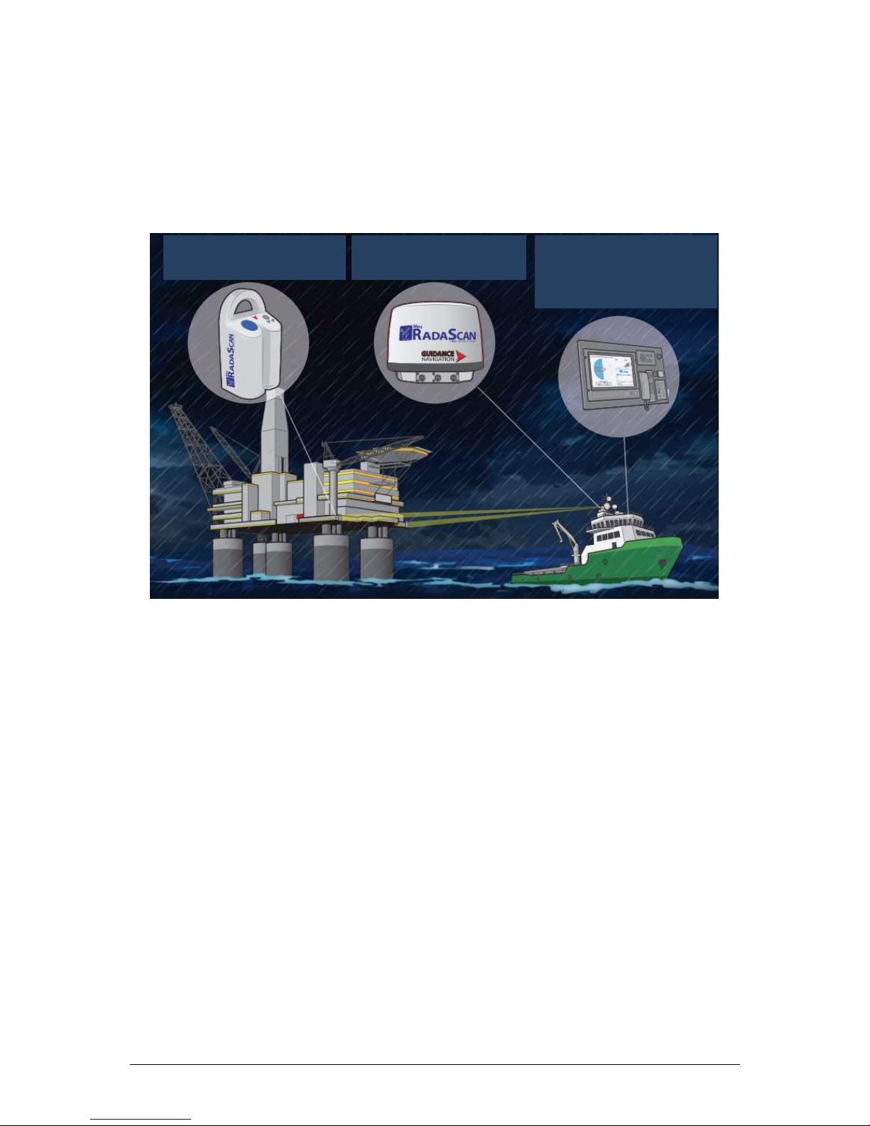
A Mini RadaScan system consists of three main components:
a sensor unit for the detection and processing of reflections;
a responder(s) unit, which reflects the signal from the sensor;
a marine computer used to configure and control the sensor using the dashboard software.
System components are shown in Figure 1.
Figure 1 –Mini RadaScan system components
Mini RadaScan Responders (one
or more) that are mounted on the
fixed platform or mobile object
Mini RadaScan Sensor that is
installed on a vessel equipped with
a DP system
Mini RadaScan Console software
is used by the DP operator to
control the Mini RadaScan Sensor. It
runs on a marine computer installed
on the vessel’s bridge

IMCA M 229 5
5Features
The sensor is a low power (1 watt) all-weather FMCW radar unit operating over a 100 MHz bandwidth in the
licence-free 9.25 GHz maritime radiolocation band. A 360° rotating antenna which is spun at a continuous rate
of 1 Hz provides unrestricted vessel manoeuvrability when trackingF targets, unlike a fixed antenna design.
The sensor works by detecting reflections from one or more ATEX certified responders mounted on a structure
such as an oil rig. The sensor calculates a relative target position which is sent to the DP system and the
dashboard.
A maximum of four responders can be detected by each sensor. They operate in four distinct frequency channels
specifically designed for the sensor and introduce a unique identifying code into the reflection to allow
unambiguous target identification and robust tracking. Each responder can also be used simultaneously by
multiple sensors which allows several vessels to obtain position information at the same time from one set of
responders.
There are two main modes of operation:
Single-target tracking provides target range and bearing measurements. It is mainly used in fixed structure
applications such as drilling rigs and production platforms;
Multi-targets tracking provides target range and bearing measurements and is also capable of calculating
vessel heading. It is mainly used in mobile structure applications such as vessel track and follow.
Once a valid relative position has been calculated, the sensor generates a standard DP telegram every second,
which is compatible with all modern DP systems.
5.1 System Advantages
All-weather operations;
uniquely coded responders ensure reliable tracking;
single or multiple responder capability;
automatic target detection;
full 360° scanning providing an unobstructed field of view;
uses coded responders making the system immune to false reflections;
responders are ATEX certified and intrinsically safe;
compatible with all leading DP systems;
versatile choice of responders to suit all applications (power cell pack powered, mains powered, or
rechargeable battery);
compact and lightweight design for easy transport and installation;
modular design to simplify servicing and maintenance.
5.2 System Disadvantages
Responder location must be selected to ensure line of sight is maintained throughout the operation;
requires the use of manufacturer’s own responders;
like all microwave based sensors, sea reflections can cause problems in still conditions if the
installation instructions are not followed carefully.
6 IMCA M 229
6Installation
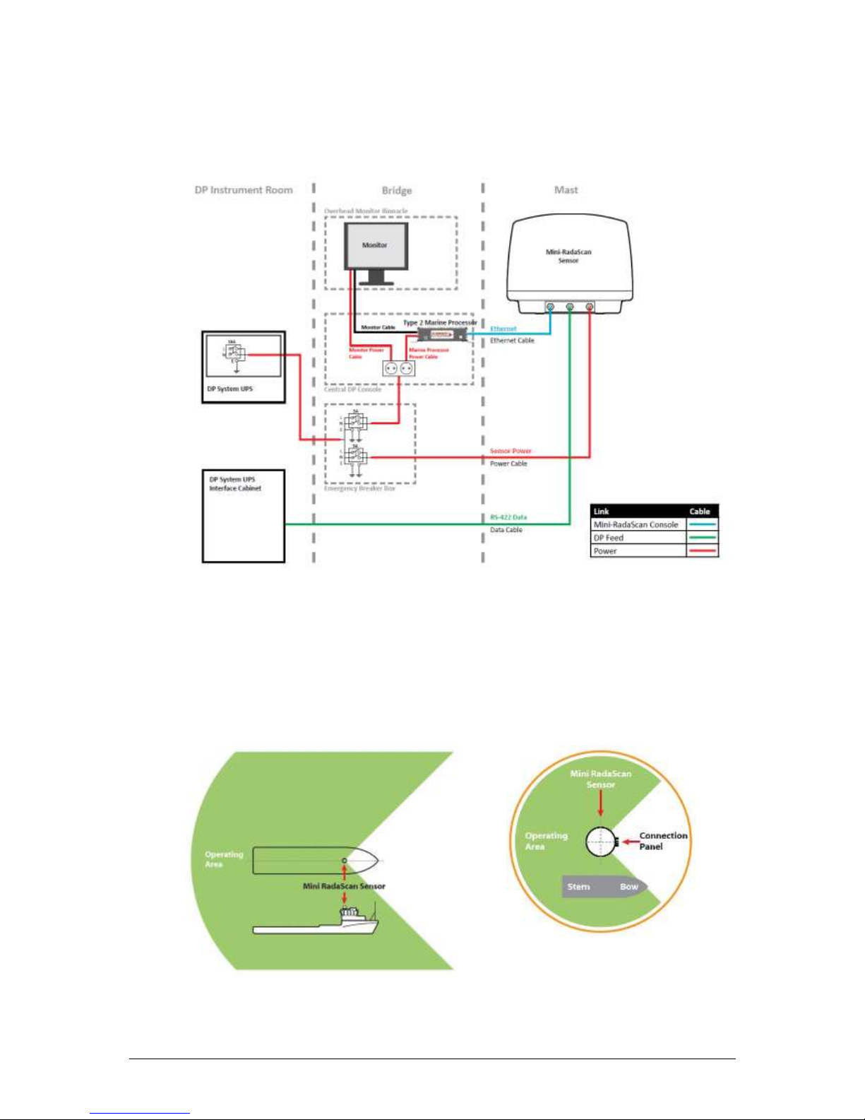
6.1 Sensor Wiring Diagram
The Mini RadaScan installation cable routing is shown in Figure 2.
Figure 2 –Mini RadaScan components cable routing
6.2 Sensor Placement
Sensor placement varies with each application therefore the information hereafter is provided as a
general guideline.
On a platform supply vessel (PSV), the typical mounting position for the sensor is above the wheelhouse,
with a clear view over the aft deck area or whichever operating area is required.
Figure 3 –Typical sensor mounting position covering deck area

IMCA M 229 7
Ideally the sensor should be mounted:
with the inspection hatch facing towards the bow (opposite the operating area), parallel to the
vessel’s fore and aft centre-line. Any deviation from the centre-line alignment can be corrected in
the dashboard software (see section 6.4);
with an unobstructed view in the expected direction of the target;
above sea-level to prevent swamping or immersion;
on a different vertical level to any radar systems operating in the X-band (see section 11.1);
on a flat, rigid, horizontal surface able to support the sensor weight and receive four M12 fixing
bolts;
allowing for easy access to the connection panel and sensor information display;
high enough to be level with the responder.
6.3 Responder Placement
To ensure highest performance of the system and quality of the relative position data sent to the DP
system, the location, range and orientation of the responders must be optimised.
Ideally responders should be mounted:
within the recommended height difference limits;
within the tilt limits;
facing the sensor directly;
in a permanent location.
Additionally the sensor blanking zone should be configured in the Dashboard software.
Following these guidelines should prevent the sensor detecting any ‘ghost’reflections from metallic
surfaces which may occur from any microwave-based system.
6.4 Calibration
6.4.1 Calibrating the Sensor Range Measurement
The sensor range measurement is factory calibrated and does not require any further steps
during installation or operation.
6.4.2 Calibrating the Sensor Bearing Measurement
Once installed on the vessel, the mounting of the sensor unit may have introduced a bearing
offset between the sensor and the vessel centre-line or heading axis. The dashboard user
interface allows the installation team to enter a fixed offset to the bearing to compensate for
it.
This change requires service access and should be carried out by trained personnel during
installation.
In multi-target tracking mode, the DP system may require that the reported heading is aligned
with the on-board gyro(s). This must be done through the Mini RadaScan user interface9and
repeated prior to commencing any DP operation.
6.4.3 Responders
The responders do not require any calibration steps and are ready for use out-of-the-box once
switched on. However the operator should pay great attention to installation guidelines to
maximise responder visibility from the sensor point of view.

8 IMCA M 229
7System Design
7.1 Sensor Properties
Figure 4 shows the internal components of the Mini RadaScan sensor.
Figure 4 –Mini RadaScan dome (left); base (centre); rotor and base (right)
There are three main modules in the sensor.
The rotor includes:
receive (Rx) and transmit (Tx) antenna arrays;
transceiver connected to the antenna arrays;
main DSP circuit board which analyses the output from the transceiver.
The chassis includes:
belt drive, motor and encoder;
bearing, heating element and slipring;
hinge to facilitate access to the elements in the base.
The base and dome assembly includes:
gasket protecting internal elements;
small observation hatch (which includes its own seal);
power supply;
vacuum fluorescent display (VFD);
mounting holes and pressure vent;
I/O for the DP system and the dashboard.
The radar dome is attached to the base by fixing screws while the gasket ensures a tight seal.
The assembly and disassembly of the dome should only be carried out by trained personnel as it may
compromise the seal and cause damage to the sensor electronics.
The antenna arrays have been designed specifically to optimise the radar beam shape for most
applications; specifically the elevation pattern is wider than the azimuth pattern to allow the system to
cope with the pitch and roll of a vessel, and to ensure good bearing accuracy.
7.1.1 VFD –Status Display
The sensor is equipped with a display for diagnostics and fault finding purposes. In particular,
it offers a convenient way for the installer to read the network IP address and the current fault
conditions when the dashboard is unable to initiate a connection to the sensor.

IMCA M 229 9
7.2 Measurement Principles
7.2.1 Range
The range measurement is the most important function of traditional radars and it is achieved
by measuring the time TRtaken by a signal to travel to the target and return (i.e. time of travel).
The more accurate the time measurement, the more accurate the range measurement R will
be.
The Mini RadaScan sensor operates using the well-known principles of FMCW radars,
9
where
the difference in frequency between the transmitted (Tx) and the echoed signal (Rx) –fb(beat
frequency) –is proportional to the transit time and c is the speed of light.
Figure 5 –FMCW beat frequency illustration (no Doppler shift)
While DP operations are usually executed at low-speed, the vessel movements are still
significant enough to introduce a non-negligible Doppler frequency shift.
If the frequency is modulated at a rate fmover a range ∆f(Figure 5), the beat frequency can be
expressed as a function of the range:
By measuring the beat frequency within a few Hz and compensating for the Doppler shift, the
Mini RadaScan sensor is able to measure the range with great accuracy. However it should be
noted that the sensor only reports the range from the sensor to the responder and not the
horizontal distance to the structure (see Figure 6).
9
Skolnik MI, 1981, Introduction to Radar Systems, McGraw-Hill Book Co., Singapore
Time
Freq
TX
RX
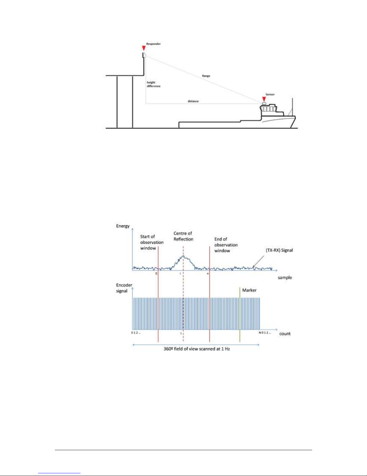
10 IMCA M 229
Figure 6 –Operation geometry and reported range
7.2.2 Bearing
The bearing measurement is derived from the energy peak of the reflection as detected by the
360º rotating antenna.
The combination of the angular position of the rotor (measured by the encoder disc) and the
reflection data (sensed by the antenna) allows for an accurate and consistent bearing
measurement.
Figure 7 –Bearing measurement
The (Tx-Rx) FMCW signal generated by the transceiver is sampled and processed so that the
energy peak can accurately be measured by a sample position i(Figure 7), which is then
converted to a bearing measurement using the corresponding encoder count I.
The encoder also provides a fixed marker position, which is indicated by the direction of the
connection panel on the sensor. It represents a fixed reference point (reference bearing) used
to provide a consistent relative bearing measurement. The convention is that the bearing
reported by the sensor shows 0º when the antenna is facing the connection panel and increases
in a clockwise direction.

IMCA M 229 11
The reported result is the calculated bearing compensated by any other bearing offset to align
the result with the vessel’s gyro (if required).
7.2.3 Target Detection and Tracking
The range and bearing are the main measurements used to form the telegram provided by the
sensor to the DP system. However there are important internal algorithms that evaluate the
quality of each reflection in order to decide if a target is acquired (i.e. acceptable for tracking)
or lost.
The target detection process has been illustrated in Figure 8. Note that the same target
detection algorithm is used during tracking when a target is lost and needs to be automatically
reacquired.
Figure 8 –Sensor processing states
For a DP operation to be initiated the operator needs to select a reflection or a number of
reflections among all the detected responders and then start tracking using the dashboard
interface.
Once a responder has been detected, motion tracking is achieved using both range and bearing
predictor algorithms. These predictors are used to optimise the observation window position
(Figure 7) to provide the best possible observation of the target during each antenna revolution.
The algorithms use gating and validation functions and do not alter the data transmitted to the
DP system. It is important for the Mini RadaScan to provide unfiltered measurements to avoid
adding any unnecessary lag or delay in the DP control loop. Any filtering/smoothing on the
data should be carried out by the vessel DP system if required.
The prediction algorithms are optimised to track responders in an environment with the
velocity and acceleration characteristics of a typical DP equipped vessel.
7.3 Responders
Figure 9 shows the components of the responder. Responders are typically permanently mounted on
platforms and are available in a number of varieties with various mounting bracket options depending
on the installation requirement.

12 IMCA M 229
Figure 9 –Responder internal view
7.3.1 Responder Antenna
The responder has been uniquely developed in conjunction with the radar sensor to ensure
that the system as a whole is easy to set up and resilient to other microwave emissions in the
operating frequency band. The responder allocated channel frequency (identifiable by the
colour) allows the sensor signal processing software to effectively reject the background clutter
normally encountered by any traditional radar system. This includes the signature of nearby
structures, such as other vessels.
Although the antenna is designed to have a wide acceptance angle (see section 12) to facilitate
target detection in a wide range of DP operations, it is strongly recommended to follow the
installation procedure (see section 6.3) to optimise the signal quality and achieve the maximum
range specified.
7.3.2 Power Source
The system offers three different types of power sources for the responders:
rechargeable battery pack;
mains power;
non-rechargeable battery primary cell pack.
The responders feature one or more status LEDs offering a convenient indication of the state
and charge level. The battery powered responder will switch itself off when it reaches critical
battery level to avoid unreliable performance.
There is no indicator to advise nearby personnel that the responder is in DP operation and
being tracked by a sensor. It is therefore important for personnel not to alter the position of
the responder once installed and it is recommended that a notice to this effect is posted next
to the responder.
IMCA M 229 13
8Operation
The operator uses the dashboard to automatically find and identify all available responders. Upon detection
these are displayed on the screen for the operator to select. Once selected and confirmed the system is switched
into tracking mode by the operator.
The Mini RadaScan blanking zone is configured once during the installation and determined by the field of view
where responders can be observed by the sensor (i.e. not obstructed by the vessel structure or any other metallic
surface).
Once installed and configured the sensor can typically be brought online using the user interface in three easy
steps:
sensor start-up and target detection;
target selection;
initiate tracking.
8.1 Dashboard
The dashboard is the graphical user interface needed to operate the Mini RadaScan. It can be controlled
using a mouse/keyboard or a touch screen display.
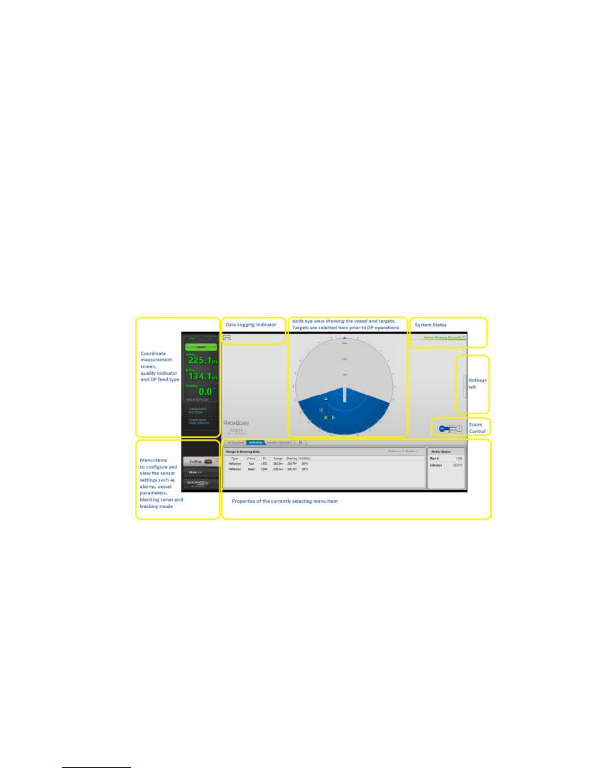
During normal operation the sensor updates the dashboard scanner display (Figure 10).
Figure 10 –Mini RadaScan dashboard
When a target has been detected, the display shows the relative position of the vessel to the
responder(s) together with any selected blanking zone. Real-time numerical values of range, bearing
and, where appropriate, heading are shown. A health bar shows the quality of the overall position
measurement.
The health is an indicator to help the operator assess the quality of the signal received by the sensor,
i.e. precursor to address any poor responder placement or vessel angle of approach.
The dashboard can be operated using two different levels of credentials:
user access level –this provides enough credentials for the user to perform most DP operations
using an already installed/configured sensor;
service access level –this offers the same credentials as the user access level but also allows the
operator to change configuration settings related to the sensor installation and the DP
configuration.

14 IMCA M 229
Multiple client dashboards can be connected to the same sensor in a master/slave configuration. This
feature provides redundancy around the vessel bridge where it is often important for multiple crew
members to have access to the Mini RadaScan data. In order to enhance safety during operations, slave
consoles are only able to view the current status of the sensor and are unable to gain service access,
start tracking or change the blanking zone. Any slave can request to be the master.
When the console is connected to a sensor and navigating, it autonomously collects detailed logs. These
logs offer valuable information to the support team to quickly diagnose any issues reported by
customers.
8.2 Multiple Sensor/Multiple Target Operation
The Mini RadaScan sensor automatically detects and identifies responders within the maximum range
and where a line of sight exists between the sensor and a responder. Each responder has a unique ID
and will respond to multiple sensors simultaneously allowing multiple vessels to operate in the same
region independently (Figure 11).
Figure 11 –Multi-responder multi-sensor operation
As illustrated in Figure 11, a DP operator can track more than one responder at the same time, whilst
another DP operator can track one or more of the same responders. Both operators can track the
same responders simultaneously.
The DP operator should refer to the Mini RadaScan documentation or contact the service team for
details to make sure the DP telegram data matches expectations of their DP system.
8.3 Mini RadaScan Interoperability and Compatibility
The performance of the Mini RadaScan is determined by the target choice. There are two formats of
target currently in field, a transponder and a responder as shown in Figure 12.
The transponder is an older generation target and its modulation type differs from the currently
manufactured responder. The modulation type of the transponder is referred to as series 1, the
modulation type currently used is referred to as series 2.
The responders are the latest generation of target and are capable of being programmed as series 1 or
series 2 or series 3. Responders are much smaller, lighter and give better performance than the earlier
transponders. The older generation transponders may not provide the maximum range performance
of the Mini RadaScan sensor.

IMCA M 229 15
Figure 12 –Target devices: transponder (left); responder (right)
When using multiple targets, because of the differing modulation types, certain rules must be adhered
to. A comprehensive guide to the differences between these targets is available.
10
10
94-0271-4-A RadaScan Series 2 Responder Buying Guide.pdf

16 IMCA M 229
9Servicing and Maintenance
The Mini RadaScan moving mechanical parts such as bearings, belt and motor should provide service free
operation for the typical DP operation usage over a period of up to 10 years. To further enhance the product
life expectancy the software will automatically initiate a suspend command and stop rotating the sensor if the DP
operator has not initiated tracking after a certain period of time.
Once installed, the sensor and responder units do not require cleaning under normal conditions. However, it is
recommended that the vessel owner carries out regular visual inspection for damage that may compromise the
integrity.
9.1 Software Upgrades
Mini RadaScan owners have access to the latest Guidance Marine software release through a web interface
or by contacting the Guidance Marine customer support team (customerservices@guidance.eu.com).
Both the Mini RadaScan sensor firmware and the dashboard can be upgraded in the field using a USB
memory stick or by transferring release files on the local network (e.g. marine computer). The two-
step procedure involves:
Remote installation of the sensor software on the sensor unit. This requires a LAN connection to
the sensor and the IP address of the sensor unit. The upgrade process is fully automated except
for the first time installation, which requires user configuration input. The installation software can
be executed using the installer user interface or a Windows command line.
Local installation of the dashboard on the marine computer. The dashboard installation works like
any standard Windows software using the supplied executable.
9.2 Recycling and Disposal
Guidance Marine employs the philosophy that supplied products do not contain hazardous substances.
A record of Mini RadaScan unit material content is available upon request.
When disposing of a Mini RadaScan sensor or responder, Guidance Marine recommends that
Mini RadaScan owners contact an electronics recycler that follows environmentally sound recycling
practices in accordance with the local rules.
Table of contents
Popular Marine Equipment manuals by other brands

Simrad
Simrad Pump-1 installation guide

Actisense
Actisense NDC-3 user manual

Simrad
Simrad EY500 instruction manual

Seastar Solutions
Seastar Solutions HA5477 installation instructions

INIM
INIM IVY Series Installation and programming manual

Francis Searchlights
Francis Searchlights LX300RC User instruction & installation manual


