INIM IVY Series Assembly instructions

1
Installation and Programming manual
SELF-POWERED SOUNDER/FLASHER FOR OUTDOOR USE
INSTALLATION
AND
PROGRAMMING
MANUAL

2
Installation and Programming manual
Table of
contents
Table of contents. . . . . . . . . . . . . . . . . . . . . . . . . . . . . . . 2
Chapter 1 Overview . . . . . . . . . . . . . . . . . . . . . . . . . . 3
1-1 Manufacturer’s Details . . . . . . . . . . . . . . . . . . . . . . . . . 3
1-2 Manual details . . . . . . . . . . . . . . . . . . . . . . . . . . . . . . . 3
1-3 Product description and models . . . . . . . . . . . . . . . . . . . 4
1-4 Signaling. . . . . . . . . . . . . . . . . . . . . . . . . . . . . . . . . . . 5
Chapter 2 General description . . . . . . . . . . . . . . . . . . . 6
2-1 Box contents . . . . . . . . . . . . . . . . . . . . . . . . . . . . . . . . 6
2-2 Technical description . . . . . . . . . . . . . . . . . . . . . . . . . . 6
Chapter 3 Installation . . . . . . . . . . . . . . . . . . . . . . . . . 9
3-1 Installation guidelines . . . . . . . . . . . . . . . . . . . . . . . . . . 9
3-2 Wiring the device . . . . . . . . . . . . . . . . . . . . . . . . . . . . . 9
3-3 Battery connections . . . . . . . . . . . . . . . . . . . . . . . . . . . 11
Chapter 4 Activation methods . . . . . . . . . . . . . . . . . . . 12
4-1 Types of signal. . . . . . . . . . . . . . . . . . . . . . . . . . . . . . . 12
4-2 Managing multi-alarm conditions . . . . . . . . . . . . . . . . . . 13
Chapter 5 Programming . . . . . . . . . . . . . . . . . . . . . . . 14
5-1 The Programming steps . . . . . . . . . . . . . . . . . . . . . . . . 14
5-2 Programming Menu . . . . . . . . . . . . . . . . . . . . . . . . . . . 15
5-3 Programming from a PC . . . . . . . . . . . . . . . . . . . . . . . . 16
Appendix A Order codes . . . . . . . . . . . . . . . . . . . . . . . . 18
Warranty . . . . . . . . . . . . . . . . . . . . . . . . . . . . . . . . . . . . 19
Limited warranty . . . . . . . . . . . . . . . . . . . . . . . . . . . . . . . 19
Copyright . . . . . . . . . . . . . . . . . . . . . . . . . . . . . . . . . . . . 19
Directive. . . . . . . . . . . . . . . . . . . . . . . . . . . . . . . . . . . . . 2004/108/CE (EMC) compli-
ance 19

Overview 3
Installation and Programming manual
Chapter 1
OVERVIEW
The IVY series offers a range of self-powered sounder/flashers
especially designed to allow maximum outdoor-installation
flexibility.
The on-board microprocessor monitors the device parameters and
assures high-reliability and first-rate performance. A voltage-free-
relay manages tamper signals and allows full-integration with every
type of system, while a fault output allows remote-management of
fault conditions.
Optimized flexibility allows you to choose the most suitable wiring
method (activation and signaling using 2 or 3 wires, etc.), and
ready-to-go factory settings (refer toTabella 6 "Programming
Menu") ensure fast and easy installation with few or even no setting
adjustments.
INIM Electronics s.r.l. also offers Ivy unit units which can be
connected to SmartLiving intrusion control panels via I-BUS (for
remote programming and management purposes), thus providing
first rate security-system customization capabilities.
1-1Manufacturer’s Details
Manufacturer: INIM Electronics s.r.l.
Place of production: Via Fosso Antico - Centobuchi
63033, Monteprandone (AP) - Italy
Tel.: +39 0735 705007
Fax: +39 0735 704912
e-mail: [email protected]
Web: www.inim.biz
ATTENTION!
Any persons authorized by the manufacturer to repair or replace
any part of this device hold authorization to work on INIM
Electronics devices only.
1-2Manual details
Issue: 2.10
Month and year: May 2010
Code: DCMIINE0IVY

4Overview
Installation and Programming manual
1-3Product description and
models
Description: Self-powered outdoor sounder/flasher
Year of production: 2010
Table 1: Models
Name Description
Ivy Standard model
Ivy-F Standard model with foam-tamper protection
Ivy-M Standard model with chrome-look casing
Ivy-FM Standard model with chrome-look casing and foam-tamper protection
Ivy-B BUS connectable model
Ivy-BF BUS connectable model with foam-tamper protection
Ivy-BM BUS connectable model with chrome-look casing
Ivy-BFM BUS potential model with chrome-look casing and foam-tamper protection
Table 2: Operating features
Features Ivy Ivy-
F
Ivy-
M
Ivy-
FM
Ivy-
B
Ivy-
BF
Ivy-
BM
Ivy-
BFM
Power and alarm input ********
Programmable input-polarity (START/STOP)****
Programmable ancillary-signal input (LED)********
Signal output with programmable polarity (FAULT)********
Tamper signal relay with programmable polarity ********
Super bright LED-technology flasher with high-power
driver circuit ********
Blow torch protection ********
Magneto-dynamic horn with automatic function control ********
Dislodgement and Open-casing protection ********
Metal guard inside ********
4 tone sounder ********
“Squawk” tone ****
Programmable sound-output time ****
Programmable volume ****
Programmable flasher sequence ********
Programmable flasher time ****
Backup battery with test circuit ********
Houses 12V, 2.1 Ah backup battery ********
IP34 Rated ********
CEI 79-2:1998 and 79-2/Ab:2000 Compliant ********
Foam protection ****
Chrome-look casing ** **

Overview 5
Installation and Programming manual
1-4Signaling
The Ivy unit provides various signals: audible, visual, activation of
the FAULT and TAMPER outputs (connectible to the intrusion-control
panel).
Each signal type can be programmed separately, combined with
other signals, or deactivated.
VISUAL SIGNALING
The super-bright flasher uses new-generation Light Emitting Diode
technology which provides maximum visual-signal clarity with extra-
low power consumption. The flasher circuit is divided into two
groups, the left group (Table 4, G) and the right group (Table 4, H).
This type of circuitry allows you to select the options on the
Programming menus.
STATUS LED -
PRG LED
The two ancillary LEDs, reveal the device status and guide you
through the programming operations (STATUS LED - Table 4, Q;
PRG LED - Table 4, R).
AUDIBLE
SIGNALING
The magneto-dynamic horn provides a choice of 4-tones, which can
be programmed with a maximum alarm time and assigned to
indicate different alarm types.
Ivy units, connected via I-BUS to the intrusion-control panel,
provide a choice of 5 tones with programmable duration and volume
options.
FAULT OUTPUT
Open-collector output with 100mA maximum current draw capacity.
During the programming phase, it is possible to select the standby
status (Normally open or Normally closed) and assign the events.
TAMPER OUTPUT
The voltage-free relay can be used to signal tamper conditions to
external devices. During the programming phase, it is possible to
select the standby status (Normally open or Normally closed) and
assign the events.
Ancillary alarm input (START)****
Stop alarm and alarm-immunity input (STOP)****
Inputs Dand Sfor I-BUS connection ****
Direct control via SmartLiving intrusion-control panel* ****
SmartLiving intrusion-control panel activation of
LEDs: STATUS and PRG ****
SmartLiving intrusion-control panel activation of
outputs: TAMPER and FAULT ****
Table 2: Operating features
Features Ivy Ivy-
F
Ivy-
M
Ivy-
FM
Ivy-
B
Ivy-
BF
Ivy-
BM
Ivy-
BFM

6General description
Installation and Programming manual
Chapter 2
GENERAL
DESCRIPTION
2-1Box contents
Inside the box you will find:
• IVY Sounder/Flasher
• 2 securing screws for the metal guard
• 2 securing screws for the plastic casing
• 5 wall plugs for mounting the backplate and tamper bracket
• Drilling pattern
• Installation and Programming manual
• Programming Table
2-2Technical description
Table 3: Technical specifications
Operating voltage 13.8 V
Minimum current draw 15 mA
Maximum current draw 150 mA
Sounder output
(l=3m) 110 dB(A)
Flash rate per minute
(programmable)
36 - 46 - 56
Maximum alarm-time
(programmable) 3 - 6 - 9 min
Protection class IP34
Operating temperature -25 to +55 °C
Backup battery 12V - 2.1Ah
Dimensions
(W x H x D) 21 x 29 x 9.5 cm
Weight (without battery) 2.2 Kg
Alimentazione
Voltaje operativo
Power
Assorbimento MAX
Consumo máx corriente
MAX power absorption
LBDTIN4AIVY
13.8 V
0.15 A
MADE
IN
ITALY
SIRENA AUTOALIMENTATA PER USO ESTERNO
SELF-POWERED SOUNDER/FLASHER FOR OUTDOOR USE
SIRENA/FLASH EXTERIOR AUTOALIMENTADA

General description 7
Installation and Programming manual
Table 4: Description of parts
AProgramming button (PAGE)
BProgramming button (SEL)
CMagneto-dynamic horn
DBattery housing
EBattery wires
FTerminal board
GLED flasher - left group
HLED flasher - right group
IFoam protection
JBlow-torch protection
KDislodgement/Open tamper protection
LWire entry
MWall-plug locations
NTamper-screw location
OMetal-guard screw locations
PExternal-casing screw locations
QSTATUS LED - Red LED
RPRG LED - Green LED
SMagneto-dynamic horn connector
TExternal casing in plastic
UCasing hinges
VMetal guard
Table 5: Terminal board
no. icon/
name Description
1+
Positive power terminal supports
13.8V
2- Negative power terminal
3START
D
Ancillary terminal with
programmable polarity for alarm
activation
Input D for I-BUS
4STOP
S
"Stop Alarm" terminal, with
programmable polarity for alarm
deactivation
Input S for I-BUS
5PRG
Input for audible/visual signaling
activation
6 Output
Open-collector output for fault
signaling
I max = 100 mA
7Output Voltage-free terminals of the relay
8
E
Q G H R
B
F
J
K
S
A
I I I

8General description
Installation and Programming manual
C
D
G H
GH
I
K
L
M
M
M
M
N
OO
PP
O
O
P
P
P
T
P
V
U
U
UU

Installation 9
Installation and Programming manual
Chapter 3
INSTALLATION
The Ivy unit should be mounted high up on a smooth surface, in
such way that it is out of reach but on view and, therefore, may
serve as a visible deterrent against break-in.
3-1Installation guidelines
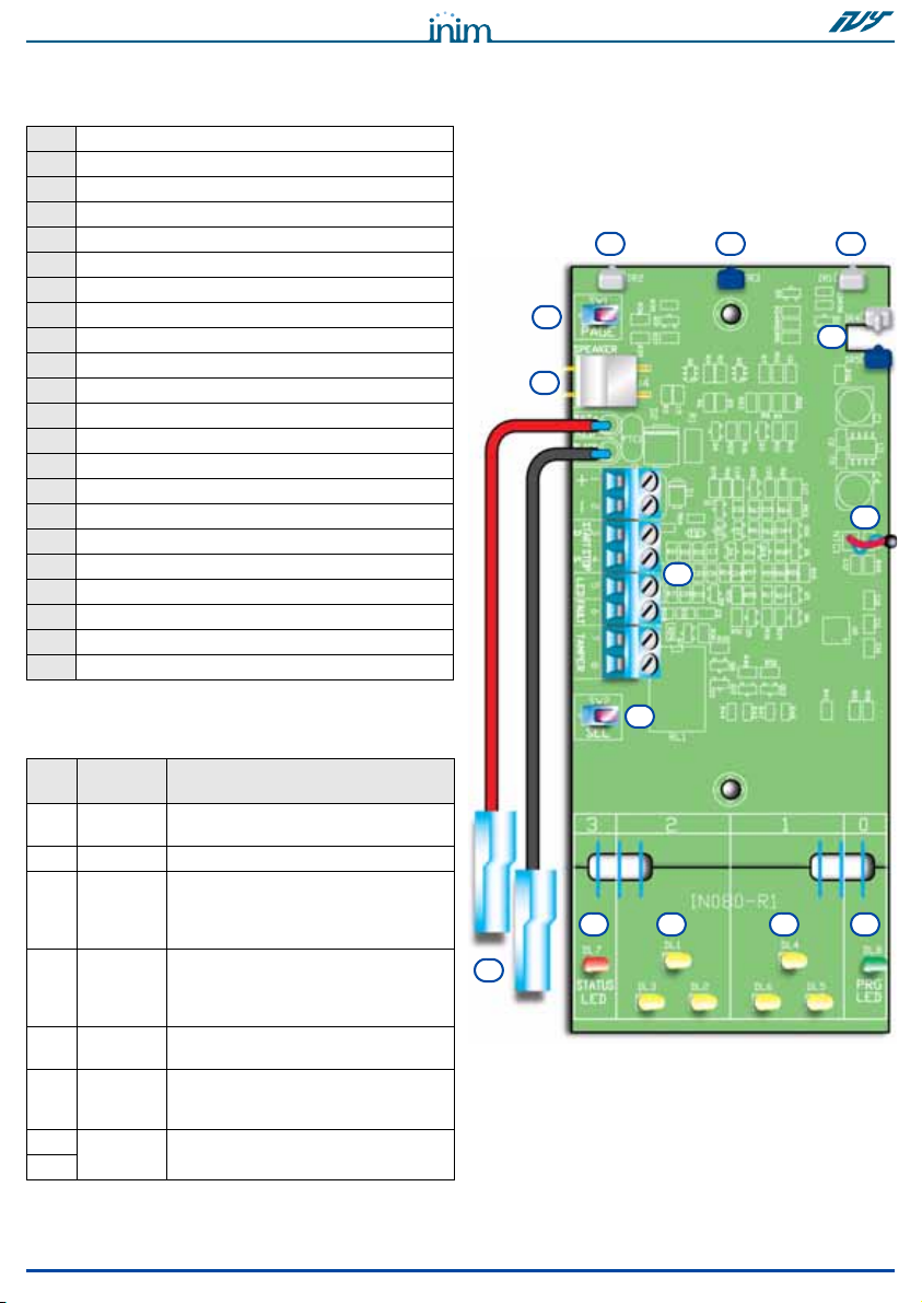
1. Remove all electrical power.
2. Open the bottom-hinged casing (Table 4, U).
3. Remove the metal guard (Table 4, V).
4. Pull the connection wires through the cable entry (Table 4, L).
5. Using the wall plugs, attach the plastic backplate to the wall
(Table 4, M). The wall plug locations are clearly marked on the
drilling-pattern (included).
6. Insert the tamper-protection screw into its location (Table 4,
N).
7. Locate the battery in its housing (Table 4, D), then connect it
by means of the battery wires (Table 4, E). Ensure that the
battery polarity is correct.
8. Complete the device wiring. During this phase, the STATUS
LED will blink at 1 second intervals.
9. Configure the device.
Note
If the factory default settings suit the installation requirements, device
configuration will be unnecessary.
10. Replace the metal guard and the plastic casing. The STATUS
LED will blink at 0.5 second intervals.
11. Powerup the device. The STATUS LED will go On (solid) for 10
seconds. The LED will go Off when the Ivy unit enters the ope-
rating phase (standby). If the Ivy unit is connected via I-BUS,
the PRG LED will signal the BUS status for 60 seconds:
- LED On solid = the BUS is not connected.
- LED blinking at 1 second intervals = the I-BUS is working but the
Ivy unit has not been enrolled on the intrusion control panel.
- LED blinking at 0.2 second intervals = the I-BUS is working and
the Ivy unit has been enrolled on the intrusion control panel.
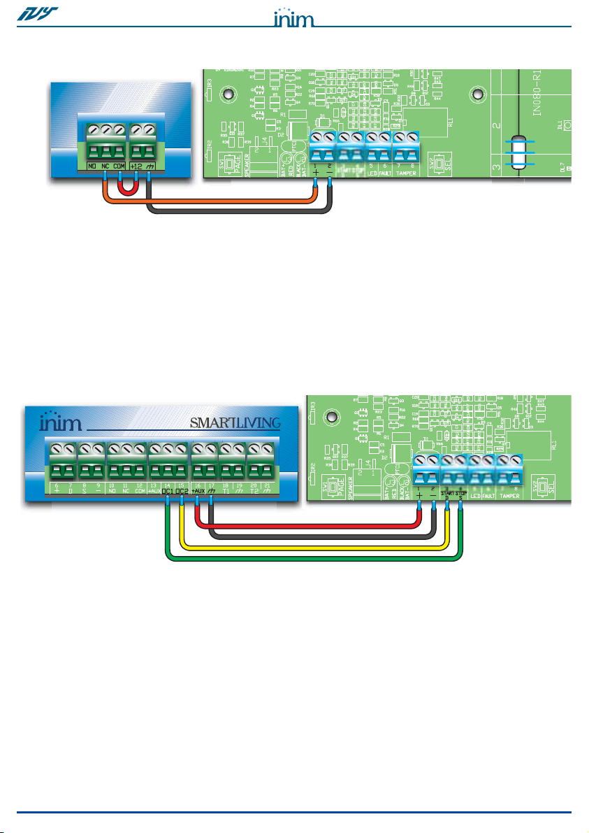
3-2Wiring the device
The following paragraphs describe the various ways of connecting
the Ivy unit to an intrusion control panel (in particular to a
SmartLiving intrusion-control panel manufactured by INIM
Electronics s.r.l.).
All connections involve the terminals on the motherboard (Table 4,
F). Each terminal can be configured separately during the
programming phase.

10 Installation
Installation and Programming manual
2 WIRE
CONNECTION
This standard wiring method activates the alarm signal by means of
a positive-power-removed signal.
4 WIRE
CONNECTION
This wiring method activates signaling via the START terminal and
deactivates it via the STOP terminal. The polarity of both inputs is
programmable.
The sounder/flasher is activated by an open-collector output (on the
intrusion control panel). By means of a second open-collector
output, you can deactivate alarm signals and disable (block) the
sounder/flasher from the intrusion control panel, for example,
during maintenance sessions.
I-BUS
CONNECTION
Only the Ivy-B, Ivy-BF, Ivy-BM and Ivy-BFM models can be
connected to the I-BUS wire. This connection allows you to program
the device and activate alarm-signaling directly from the panel.
In addition, connection of the I-BUS wire to terminal "+", provides a
power source which enables the Ivy unit to activate alarm-signaling
(in accordance with its programmed parameters) in the event of
wire-cutting tamper.
Each time the SmartLiving panel resets the BUS and restarts the
connected peripherals, the Ivy unit will run a 60-second status
check on the BUS, as described in paragraph 3-1 Installation
guidelines.

Installation 11
Installation and Programming manual
EXTRA
CONNECTIONS
Connection of the LED terminal to an open-collector output, will
allow management of the STATUS and PRG LEDs, flasher and horn
directly from the intrusion-control panel (as programmed).
Connection of the FAULT and TAMPER outputs to a terminal on the
intrusion control panel allows signaling of the associated events.
This function allows fault and tamper signals to be transmitted
without activating the visual-signaling components.
3-3Battery connections
This device requires a 12V, 2.1Ah battery (not included), which must
be connected by means of the respective wires (Table 4, E) . Take
care to respect the battery polarity during the installation phase
(red=positive; black=negative).
The battery-efficiency test will run 60 minutes after installation and
every 10 minutes thereafter. In the event of an alarm, the battery
test will be delayed by 60 minutes.
Failure of the battery-efficiency test will generate the respective
signal (Table 6, Low battery). If the battery voltage drops below 11V
during an alarm event, the horn will deactivate automatically,
however, all other signaling will continue until the voltage drops
below 10V.
All functions will be re-established when the battery voltage restores
to 12V.

12 Activation methods
Installation and Programming manual
Chapter 4
ACTIVATION METHODS
The Ivy unit can be triggered by signals from the panel, depending
on the wiring method used and also by events generated by the Ivy
unit itself.
Signaling will cease when one of the following conditions occurs:
• the alarm condition clears;
• the maximum alarm time expires (in this case, only the audible
signaling will cease);
• the STOP signal activates.
If, during an active alarm, the maximum audible-alarm time expires
(Table 6, Maximum duration of audible signaling), audible signaling
will cease but visual signaling will continue until the trigger condition
clears.
4-1Types of signal
SOUNDER/
FLASHER EVENTS
The Ivy unit processes the signals it picks up and then generates the
respective events (which can be associated with one or more
signals).
The Ivy unit can generate the following events:
• Power failure
•Lowbattery
•Opencasing
• Device dislodgement
• Foam tamper (or similar) in the horn
• Blow torch tamper
• Horn damage
•I-BUSloss
Note
The audible and visual signaling triggered by “open casing”, “foam
tamper” and “blow torch tamper” events will clear after 30s, or
immediately on receiving the STOP signal.
Note
The event "Open casing" of a Ivy connected by BUS unit does not
trigger audible signaling when the connected anti-intrusion control
panel is in "Programming" mode.
MAINS FAILURE
This signaling method is widely applied as it ensures intrinsic
protection against wire-cutting. This activation method triggers
audible and visual signals (sounder and flasher) when the primary
mains power fails.

Activation methods 13
Installation and Programming manual
START INPUT
The START ancillary input is completely programmable, therefore, it
can activate the sounder/flasher by means of either positive signals
(Applied/Removed) or negative signals (Applied/Removed).
STOP INPUT
The STOP signal allows you to force the Ivy unit to standby status
thus blocking all signaling. Once this signal is removed, the device
will restart the evaluation process and if the alarm conditions are
still active, it will trigger the respective signals.
Note
Although the STOP input is fully programmable, the manufacturer
strongly recommends an “applied” signal configuration rather than a
“removed” signal configuration, in order to avoid the risk of disablement
in the event of wire cutting.
LED INPUT
This input (activates when connected to negative) operates as an
ancillary channel which the panel can use to activate any type of
signal, in accordance with the configuration of the Ivy unit.
I-BUS
All I-BUS related activations must be programmed via the intrusion
-control panel. Panel events are capable of generating signaling
directly on the sounder/flasher, without activating terminals or
outputs.
Additionally, programming the audible/visual signal parameters
from the intrusion control panel is more flexible than programming
them directly via the Ivy unit.
NON-
PROGRAMMABLE
EVENTS
The Ivy unit can be also triggered by default activations that are not
editable by programming. PRG LED becomes ON solid in case of the
following events:
•Opencasing
• Device dislodgement
• Foam tamper (or similar) in the horn
• Blow torch tamper
4-2Managing multi-alarm
conditions
There is no priority amongst the various signals. If the Ivy unit
detects signals, it will activate the programmed signaling cycle and,
in the event of concurrent activations, add on the respective signals.
Restoral of a detected signal annuls the respective alarm cycle
automatically, but it does not annul alarm cycles relating to other
signals. The Ivy unit will restore to standby status when all alarm
conditions cease.

14 Programming
Installation and Programming manual
Chapter 5
PROGRAMMING
The programming session cannot begin until after first startup,
therefore, it is necessary to ensure that:
• all power sources to the Ivy unit (mains and battery) are
disconnected;
• the tamper protection is open;
• the Intrusion control panel will allow you to work on the Ivy unit
without generating alarms (for example; put the intrusion-
control panel in Programming status).
The Programming menu allows you to program and change the
device configuration. Access to programming is indicated by blinking
on the LEDs (STATUS LED , left flasher, right flasher and PRG LED).
The PAGE button (Table 4, A) allows you to access the menus.
5-1The Programming steps
1. Remove the cover.
2. Powerup the device; the STATUS LED will blink at 1 second
intervals. The device will exit the programming phase and step
back to this point if no command is received within the allowed
time.
3. Press and hold the PAGE button until the STATUS LED goes
Off.
4. Use the PAGE button to move to the different options on the
menu The LED combination (the LEDs which blink) identifies
the option concerned.
5. Press the SEL button (Table 4, B), to select the required
option. The LED combination (the LEDs which are On solid)
indicates the current setting of the option concerned.
6. To change a setting, press the SEL button again until the LED
combination indicates the desired setting.
7. The PAGE button will allow you to select the desired menu.
8. To exit the Programming session, wait 20 seconds (do not
press any buttons); the LEDs will blink to signal that the ses-
sion has ended. If you wish to exit without saving, select “0”
from the menu.
9. To complete the installation phase, work through the steps
indicated in paragraph 3-1 Installation guidelines from point
10.
3
Visual signaling
210
left right
PRG
LED
PRG
LED

Programming 15
Installation and Programming manual
5-2Programming Menu
The following table shows, under the caption “Menu”, all the options
on the Programming menu and their respective LED combinations:
*: Options present on I-BUS- connectable Ivy models only
**: When this option is enabled, the LED STATUS becomes ON solid
Table 6: Programming Menu
Menu Options
Num.
LED
combinations
Menu
options
0
Exit without
saving
////Exit
1
START input
Negative
applied
Positive
applied
Negative
removed
Positive
removed Deactivated
I-BUS loss
delay *
+ 8 minutes + 4 minutes + 2 minutes + 1 minutes Deactivated
2
STOP input
Negative
applied
Positive
applied
Negative
removed
Positive
removed Deactivated
I-BUS lost *
TAMPER
Output
TAMPER
Output
Visual
signaling
Sounder Deactivated
3
Audible
signaling
Tone 4 Tone 3 Tone 2 Tone 1 /
4
Maximum
duration of
audible
signaling
*9 minutes 6 minutes 3 minutes /
5
Flashes
Blinking on
the LEDs
connected to
the LED Input
56 flashes/
minute
46 flashes/
minute
36 flashes/
minute /
6
Outputs:
TAMPER and
FAULT
TAMPER
normally
closed
TAMPER
normally
open
FAULT
normally
closed
FAULT
normally
open
/
7
Activation of
the START
input
STATUS
LED
PRG
LED
Visual
signaling
Sounder Deactivated
(empty) *
/////
8
Activation of
the LED input
STATUS
LED
PRG
LED
Visual
signaling
Sounder Deactivated
9
Power failure
FAULT
Output
TAMPER
Output
Visual
signaling
Sounder Deactivated
10
Open-casing
signal
FAULT
Output
TAMPER
Output
Visual
signaling
Sounder Deactivated
11
Foam tamper
signal
FAULT
Output
TAMPER
Output
Visual
signaling
Sounder Deactivated
12
Blow-torch
tamper signal
FAULT
Output
TAMPER
Output
Visual
signaling
Sounder Deactivated
13
Horn trouble
FAULT
Output
TAMPER
Output
STATUS
LED
PRG
LED Deactivated
14
Low battery
FAULT
Output
TAMPER
Output
STATUS
LED
PRG
LED Deactivated
15
Reset default
/ Address *
//
/
/Default
+8+4+2+1
3210
3210
3210
3210
3210
3210

16 Programming
Installation and Programming manual
•0- PRG LED
•1- Right LED on flasher circuit
•2- Left LED on flasher circuit
•3- STATUS LED
•- LED Off
•- LED On solid
•- LED blinking
Instead (under the caption “Options”), the programmable settings
for each item, highlighted on a grey background ( ) are the
options enabled at default.
The following section describes the menu options.
0 -
Exit without saving
: when you come to this option, wait 20
seconds for the device to exit the programming phase without
saving.
1 - START input: allows you to select the polarity of the START
input.
- I-BUS Loss delay: allows you to select the time (15 minutes
at default) which must pass before the loss of the I-BUS is
signaled.
2 - STOP input: allows you to select the polarity of the STOP
input.
- BUS Loss: allows you to select the type of signaling associa-
ted with the loss of the I-BUS.
3 - Audible signaling: allows you to select the type of sound
emitted by the horn.
4 - Maximum audible-signal time: allows you to select the
maximum time the horn will sound for, after which only other
types of signaling will continue until the Ivy unit restores to
standby.
5 - Visual signals: the first option allows blinking on the STATUS
and PRG LEDs activated by the LED input; the other options
allow you to select the visual signal on the flasher.
6 - TAMPER and FAULT Outputs: allows you to select the type
of contact (normally open or normally closed) of the outputs
during standby status.
7/8 -START/LED Input Activation: allows you to select the
signaling associated with the activation of this input.
9/14 -Power failure; Open-casing tamper; Foam tamper,
Blow-torch tamper; Horn damage; Low battery: allows
you to select the signaling associated with the event.
15 - Restore Default / Address: if you select the option with "all
LEDs On solid", the current programming will restore to
factory default settings. Selection of the BUS Address is achie-
ved by the summing the value corresponding to each LED On
solid (max. 10); restoral to default does not change the assi-
gned address.
5-3Programming from a PC
Only BUS-connectable Ivy units can be programmed via PC.
The SmartLeague software will allow you to program/change the
previously mentioned parameters/settings of the Ivy unit.
Additionally, the software application allows you to program the
“patterns”, that is to say, the type of signaling, duration and volume
of the audible signals generated by the SmartLiving intrusion control
panel.

Programming 17
Installation and Programming manual
The parameters of each pattern are as follows:
•
Description
- 16 character description of the pattern
•
Sounder ON/OFF
- enables/disables activation of the sounder
•
Sounder time
- signalling activation time of the sounder; expressed in
seconds (from 1 to 125) or minutes (from 1 to 125)
•
Sounder tone
- sound type selectable from 5 tones
•
Sounder volume
- volume selectable from 17 levels
•
Flasher ON/OFF
- enables/disables activation of the flasher
•
Flasher time
- signalling activation time of the flasher; expressed in
seconds or minutes or "continuous". If you select "continuous", the
flasher will remain active without limitation or at least until it receives a
"shutoff" command. However, if the flasher is triggered in continuous
mode by a zone alarm, terminal tamper, partition alarm or partition
tamper, the flasher can also be deactivated by a memory reset
command.
•
Flasher type
- selectable from the following types:
-1=36flash/min
-2=46flash/min
-3=56flash/min
- 4=ON solid
•
STATUS LED ON/OFF
- enable/disable activation of the STATUS LED
•
PRG LED ON/OFF
- enable/disable activation of the PRG LED
•
TAMPER output ON/OFF
- enable/disable activation of the TAMPER
output
•
FAULT output ON/OFF
- enable/disable activation of the FAULT output
8 types/pattern are available, programmed in the following way at
default:
Table 7: Patterns - default
n
Description Sounder
ON/OFF
Sounder
time
(seconds)
Sounder
tone
Volume
sirena
Flasher
ON/OFF
Flasher
time
(seconds)
Flasher
type
(flash/min)
LED STATUS
LED PRG
TAMPER output
FAULT output
ON/OFF
1 Burglar ON 180 Tone 1 16 ON 180 56 OFF
2Burglar low
volume ON 180 Tone 1 6 ON 180 56 OFF
3 Fire ON 180 Tone 3 16 ON 180 56 OFF
4 Tamper ON 180 Tone 1 16 ON 180 36 OFF
5 Pre-alarm ON 30 Tone 1 0 ON 30 36 OFF
6 Tecno ON 3 Tone 1 6 OFF OFF
7 Signalling ON 1 Tone 5 0 ON 3 ON solid OFF
8Bell ON 3 Tone4 0 ON 3 ONsolid OFF
A shutoff pattern is illustrated below:
Shutoff OFF no effect OFF no effect OFF

18 Order codes
Installation and Programming manual
Appendix A
ORDER CODES
Code Product
DCMIINE0IVY Installation and programming guide
Ivy Self-powered outdoor sounder/flasher
Ivy-B Self-powered outdoor sounder/flasher connectable to BUS
Ivy-BF Self-powered outdoor sounder/flasher connectable to BUS with foam tamper
protection
Ivy-BFM Chrome-look self-powered outdoor sounder/flasher connectable to BUS with foam
tamper protection
Ivy-BM Chrome-look self-powered outdoor sounder/flasher connectable to BUS
Ivy-F Self-powered outdoor sounder/flasher with foam tamper protection
Ivy-FM Chrome-look self-powered outdoor sounder/flasher with foam tamper protection
Ivy-M Chrome-look self-powered outdoor sounder/flasher
LINKIBUS Temporary I-BUS link cable
SmartLeague Programming and management software for INIM devices
SmartLiving505 Intrusion control panel with 5 terminals, 5 partitions, 1.2 A switching power supply,
metal casing for 7Ah battery
SmartLiving515 Intrusion control panel with 5 to 15 terminals, 5 partitions, 1.2 A switching power
supply, metal casing for 7Ah battery
SmartLiving1050 Intrusion control panel with 10 to 50 terminals, 10 partitions, 3A switching power
supply, metal casing for 7Ah battery
SmartLiving1050L Intrusion control panel with 10 to 50 terminals, 10 partitions, 3A switching power
supply, metal casing for 17Ah battery
SmartLiving10100L Intrusion control panel with 10 to 100 terminals, 15 partitions, 5A switching power
supply, optional TCP/IP connectivity, metal casing for 17Ah battery

19
Installation and Programming manual
WarrantyINIM Electronics s.r.l. (Seller, Our, Us, ) warrants the original
purchaser that this product shall be free from defects in materials
and workmanship under normal use for a period of 24 months. As
INIM Electronics s.r.l. does not install this product directly, and due
to the possibility that it may be used with other equipment not
approved by Us; INIM Electronics s.r.l. does not warrant against loss
of quality, degradation of performance of this product or actual
damage that results from the use of products, parts or other
replaceable items (such as consumables) that are neither made nor
recommended by INIM Electronics. Seller obligation and liability
under this warranty is expressly limited to repairing or replacing, at
Seller's option, any product not meeting the specifications. In no
event shall INIM Electronics s.r.l. be liable to the purchaser or any
other person for any loss or damage whether direct ot indirect or
consequential or incidental, including without limitation, any
damages for lost profits, stolen goods, or claims by any other party
caused by defective products or otherwise arising from the incorrect
or otherwise improper installation or use of this product.
This warranty applies only to defects in parts and workmanship
relating to normal use. It does not cover:
• damage arising from improper maintenance or negligence
• damage caused by fire, flood, wind or lightning
•vandalism
• fair wear and tear
INIM Electronics s.r.l. shall, at its option, repair or replace any
defective products. Improper use, that is, use for purposes other
than those mentioned in this manual will void the warranty. Contact
Our authorized dealer, or visit our website for further information
regarding this warranty.
Limited
warranty
INIM Electronics s.r.l. shall not be liable to the purchaser or any
other person for damage arising from improper storage, handling or
use of this product.
Installation of this Product must be carried out by qualified persons
appointed by INIM Electronics. Installation of this Product must be
carried out in accordance with Our instructions in the product
manual.
CopyrightThe information contained in this document is the sole property of
INIM Electronics s.r.l. No part may be copied without written
authorization from INIM Electronics s.r.l.
All rights reserved.
Directive
2004/108/CE
(EMC)
compliance
Hereby INIM Electronics s.r.l. declares that IVY sounders are in
compliance with the essential requirements and other relevant
provisions of Directive 2004/108/CE.
The full declarations of conformity of the above-mentioned devices
are available at URL: www.inim.biz

20
Installation and Programming manual
DCMIINE0IVY-R210-20100521
ISO 9001: 2008 registered company
This manual suits for next models
8
Table of contents
Other INIM Marine Equipment manuals
Popular Marine Equipment manuals by other brands

DIGITAL YACHT
DIGITAL YACHT AQUA COMPACT PRO MARINE PC Installation and instruction manual

Simrad
Simrad NSS9 evo3S Operator's manual

B & G
B & G H3000 Pilot owner's manual

JRC
JRC Inmarsat FleetBroadband JUE-501 instruction manual

Star
Star Sea Data Installation and user manual

E2S
E2S A105N installation instructions