B&G Network Series User manual

HB-0502-03 1
CONTENTS
CONTENTS 1
GENERAL INTRODUCTION TO B&G NETWORK 2
INTRODUCTION TO NETWORK WIND 3
EXAMPLE SYSTEMS USING NETWORK WIND 4
SELECTING THE DISPLAY MODE 5
THE ANALOGUE DIAL AND POINTER 6
USING THE APP. KEY 6
USING THE TRUE KEY 7
USING THE VOLTS KEY 7
USING THE SETUP KEY 8
SETTING THE DIGITAL DISPLAY DAMPING 9
SETTING THE ANALOGUE DISPLAY DAMPING 10
WIND SENSOR ALIGNMENT 11
ADJUSTING THE WIND SENSOR OFFSET 12
USING THE LIGHTS KEY 13
INSTALLATION 14
SITING THE UNIT 14
MOUNTING THE UNIT 14
SPECIFICATION 16
ABBREVIATIONS AND DEFINITIONS 17
THE WIND TRIANGLE 17
CONDITIONS OF WARRANTY

HB-0502-03 2
GENERAL INTRODUCTION TO B&G NETWORK
The B&G Network range of instruments is designed to be
used as individual units or connected together to form an
integrated navigational system. A single network cable is
used to carry data and power between units. The latest
technology and screened cables throughout the Network
System ensure the ultimate protection from interference
between units and other systems. All Network instruments
can be linked to Network PILOT, Network CHART, Network
GPS or Network LORAN receivers or via NMEA 0183 (v1.5)
to other navigational equipment.
INSTRUMENTS NAVIGATIONAL AIDS
Network SPEED Network GPS
Network DEPTH Network LORAN
Network QUAD Network NAV
Network WIND Network CHART
Network TACK
Network DATA
AUTOPILOTS COMMUNICATIONS
Network PILOT Network VHF

HB-0502-03 3
INTRODUCTION TO NETWORK WIND
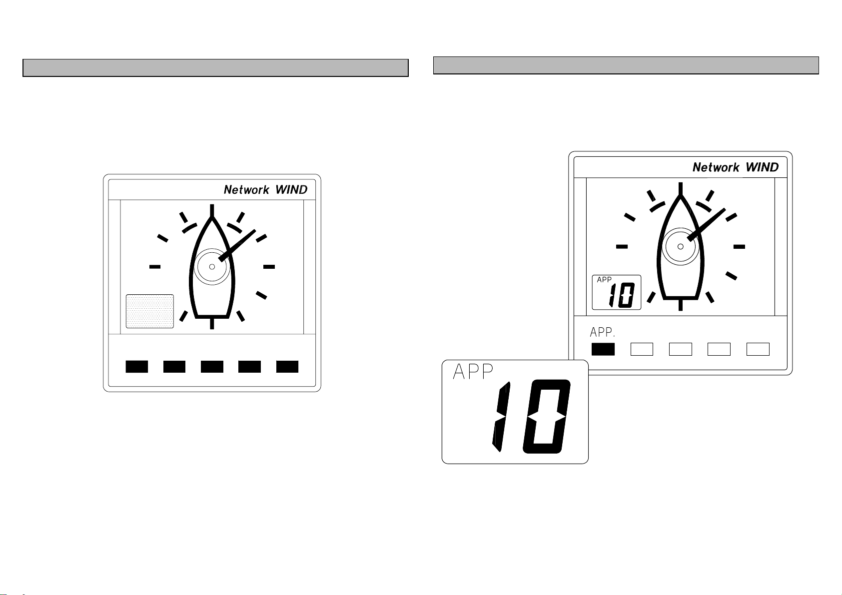
The Network WIND unit measures and displays wind
information on an analogue 3600Apparent Wind Angle meter
and a back-lit Liquid Crystal Display (LCD). The five keys
allow selection of the information displayed on the LCD and
setting of the units mode, Wind Sensor offset calibration and
display damping.
It can operate as the main Network WIND unit either alone or
as part of an Intregrated Network Instrument System taking
inputs directly from a Wind Sensor which plugs into the
socket at the rear of the display, or as a repeater of wind
information received via the two Network cable tails. For true
wind functions Network WIND must be connected to a
system that contains a Network SPEED or Network QUAD
unit as boat speed is required.
The unit is able to transmit NMEA 0183 v1.5 data via the
network cables to other Network units and connect to an
NMEA device e.g. a position fixer, with a special NMEA
output cable.
The unit has no internal alarm or alarm functions.
IMPORTANT NOTE
Your Network WIND unit must be setup and calibrated
correctly before it is used as part of a navigational system.
NETWORK WIND DISPLAY UNIT

HB-0502-03 4
EXAMPLES SYSTEMS USING NETWORK WIND
Only one Network WIND unit should have a wind sensor
connected to it and set to transducer mode. Up to three more
Network WIND units can be connected on to the system
network, these must be set to repeater mode.
See SELECTING THE DISPLAY MODE. For True wind
functions the Network WIND must be part of a system
containing Network SPEED or Network QUAD.
Network SPEED, Network DEPTH, Network WIND and
Network TACK (magnified wind angle).
The Network units can be connected together in any order as
data is shared via the system network cable link.
Capteur de vent
QUAD WIND
Élément maître WIND
Répétiteur
WIND
Répétiteur
Speedo
Sondeur
QUAD WIND TACK

HB-0502-03 5
SELECTING THE DISPLAY MODE
The Network WIND unit has three operating modes.
The correct mode must be selected for your Network
system to operate correctly.
tu Unit mode, the unit uses and displays wind data from
a wind sensor connected directly into the display
unit. Your unit is supplied in this mode.
tr Repeater mode, the unit operates as a wind repeater
using data from the system network.
td Demo mode, the unit runs an internal demonstration
program.
Press SETUP key 4 times
to display current mode. Press ENTER key if the
mode needs to be
changed. The display
flashes.
Use !
!!
!or "
""
"key to
change the mode. Press ENTER key to
memorise the new mode.
After 30 secs the display will
revert to previously selected
display.

HB-0502-03 6
THE ANALOGUE DIAL AND POINTER
The analogue pointer always indicates Apparent Wind Angle
on the 3600dial. Each division marker is at 300intervals. The
LCD is offset to the left so when running with the wind astern
the wind angle can still be read clearly.
USING THE APP. KEY
Press the APP. key to display Apparent Wind Speed on the
LCD. The LCD APP legend will be displayed.

HB-0502-03 7
USING THE TRUE KEY
Press the TRUE key to display True Wind Speed on the
LCD. The LCD TRUE legend will be displayed.
If boat speed data is not available the LCD digits will be blank
and the TRUE legend will be displayed.
USING THE VOLTS KEY
Press the VOLTS key to display Battery Volts on the LCD.
The LCD Vlegend will be displayed.

HB-0502-03 8
USING THE SETUP KEY
Press the SETUP key to cycle through the following options
on the LCD.
dS Damping Speed, this is the response time of the LCD
wind speed display.
dA Damping Analogue, this is the response time of the
analogue pointer.
OF Offset, this is the offset calibration value to correct
for Wind Sensor misalignment.
tu Display mode, this is the operating mode of the
Network WIND unit.

HB-0502-03 9
LCD WIND SPEED DAMPING
The wind speed damping allows the response time of the
LCD wind speed display to be slowed down if the values are
to jumpy in gusty conditions. The damping works by
averaging the wind speed over a set time period, the longer
the time period the smoother the displayed values, however
the longer it takes to see any change.
Network WIND allows selection of four damping values, d1,
d2, d4, d8, each is the approximate time in seconds. The
unit is supplied with a factory set value of d4.

HB-0502-03 10
Press SETUP key
once to display dS,
damping Speed.
Press ENTER key to
display current
damping speed. The
display flashes.
Use !
!!
!or "
""
"key to
cycle through the
damping values.
Press ENTER key to
memorise the new value.
After 30 secs the display
will revert to previously
selected display.

HB-0502-03 11
ANALOGUE POINTER DAMPING
The analogue pointer damping allows the response time of
the analogue display to be slowed down if the values are to
jumpy in gusty conditions. The damping works by averaging
the wind angle over a set time period, the longer the time
period the smoother the displayed values, however the
longer it takes to see any change.
Network WIND allows selection of four damping values, d1,
d2, d4, d8, each is the approximate time in seconds. The
unit is supplied with a factory set value of d1.
Press SETUP key
twice to display dA,
damping Analogue.
Press ENTER key to
display current
damping speed. The
display flashes.
Use !
!!
!or "
""
"key to
cycle through the
damping values.
Press ENTER key to
memorise the new value.
After 30 secs the display will
revert to previously selected
display.

HB-0502-03 12
WIND SENSOR MISALIGNMENT CORRECTION
For accurate wind angle readings the wind sensor should be
pointing forward and aligned with the centreline of the boat.
However, this is not always possible, so Network WIND
allows a wind sensor offset value to be entered to
compensate for the misalignment electronically.
Firstly the amount of misalignment must be found. The
following procedure will enable you, during the course of a
sea trial, to establish the value.
1Sail close-hauled on a Port Tack, note the set of all the
sails.
When the conditions are steady, note the apparent wind
angle (AWA) on the analogue display, e.g. Port 350.
NOTE: If you have Network TACK or Network DATA the
AWA can also be read from these.
2Turn the boat until close-hauled on a Starboard Tack,
make sure the sails are set as for the Port Tack.
When the conditions are steady, note the AWA on this
tack, e.g. 250.
3Determine the direction of the misalignment and wind
sensor offset value by subtracting the Starboard value
from the Port value, then dividing by two.
e.g. Port 35 - Starboard 25 = 10 ÷2 = 5.
If the value is positive the misalignment is to Port, if the
value is negative it is to Starboard.
4Enter the wind sensor offset value into the Network
WIND unit's memory by following the procedure below.
5The alignment procedure should be repeated until the
displayed AWA is equal on both tacks.

HB-0502-03 13
ADJUSTING THE WIND SENSOR OFFSET
If the value calculated is positive, the wind sensor is
misaligned to Port. To correct this the analogue pointer must
be offset clockwise (towards starboard) by the value
calculated. Use the !
!!
!key (up) to change the value displayed
on the LCD.
If the value is negative, the wind sensor is misaligned to
Starboard. To correct this the analogue pointer must be
offset anti-clockwise (to port) by the value calculated. Use the
"
""
"key (down) to change the value displayed on the LCD.
Press SETUP key 3
times to display OF,
OFfset value.
Press ENTER key to
display current value.
The display flashes.
Factory set to zero.
Use !
!!
!or "
""
"key to
adjust the value.
!
!!
!= clockwise
"
""
"= anti-clockwise.
Press ENTER key to
memorise the new
value. After 30 secs
the display will revert
to previously selected
display.

HB-0502-03 14
USING THE LIGHTS KEY
The Network WIND Display unit has 3 levels of illumination
and off, controlled by the LIGHTS key. The level selected is
for the whole Network system.
• L0 OFF
• L3 High
• L2 Medium
• L1 Low
The LIGHTS key also changes the illumination level of the
key legends, it always remains illuminated so even in
complete darkness the key can be located.

HB-0502-03 15
INSTALLATION
The display heads are supplied with a clip-in mounting
bracket which allows for easy installation, access from
behind is not necessary to secure the unit in place. However
to prevent theft and permanently fix the unit in position,
locking studs and thumb nuts are supplied.
SITING THE UNIT
All Network Instruments are designed for mounting on or
below deck. A mounting position should be selected where
they are:
•Easy to read by the helmsman
•On a smooth and flat surface
•At least 100mm (4") from a compass
•Accessible from behind for fitting locking studs if
required.
MOUNTING THE UNIT
Use the cutting template supplied to mark the centres of the
holes for the self-tapping screw, the fixing stud holes and the
mounting bracket.
•The template allows 4mm (5/32") between adjacent
units for the suncover, increase this distance if required to
maximum of 60mm (2 3/8") between units or 180mm
(3 1/8") between centres. For greater distances between
units extension cables are available.
•Use a 70mm (2 3/4") diameter hole-cutter for the
mounting bracket hole.
•Use a 2.9mm for the self-tapping screw holes.
•Use a 5mm (3/32") drill for the locking stud holes.
•Secure the mounting bracket to the bulkhead with the
self-tapping screws supplied
•Fit the rubber sealing gasket around the mounting
bracket.
•Screw the locking studs into the back of the display
head (if required).
•Carefully pass the cable tails through the mounting
bracket hole, connect the cables to the main units.
•Clip the display head into the mounting bracket.
•Secure the instrument with the thumb nuts supplied.

HB-0502-03 16
INSTALLATION

HB-0502-03 17
SPECIFICATION
PHYSICAL PARAMETERS
Construction High impact ABS plastic
Window Acrylic
Display Analogue dial and pointer
Back-lit Liquid Crystal Display:
Digits: 12mm 0.47"
Dimensions 110 x 110 x 25.4mm 4 x 4 x 1"
Requires 65mm 2.6" depth behind
bulkhead for display barrel.
Weight 0.3 kg 0.66lbs
ENVIRONMENTAL
Operating Temp -10 to +550C @ 93%RH
+14 to +1310F @ 93%RH
Storage Temp -25 to +700C @ 95%RH
-13 to +1580F @ 93%RH
Humidity Up to 95%RH
Sealing Fully sealed front, suitable for bulkhead cockpit
mounting. Vented barrel to prevent condensation.
ELECTRICAL
Power Supply 12V DC nominal (10 to 16V)
Operating Current 40mA typical, 100mA illuminated
Protection Connect via external 5A fuse or
circuit breaker.
CABLES AND CONNECTIONS
Connection to adjacent units is via cable tails fitted with either
a plug or a socket. Extension cables are available from your
dealer. The cable tails carry power and NMEA data between
units.
ALARM
There is no internal audible alarm
NMEA OUTPUT SENTENCES
$IIHDM Heading
$IIVHW Speed and Heading
$IIDBT Depth
$IIVWR Apparent wind angle and speed
$IIMTW Sea temperature

HB-0502-03 18
ABBREVIATIONS AND DEFINITIONS
AWA Apparent Wind Angle - The angle between the
boat's bow and the wind blowing across the
deck (at mast height).
AWS Apparent Wind Speed - The wind speed across
the deck (at mast height).
TWA True Wind Angle - The wind angle between the
boat's heading and the true wind (at mast
height). This is calculated from AWA, AWS and
boat speed. This is the wind relative to the
water, not the land.
TWS True Wind Speed - The wind speed over the water,
independent of the boat's motion through it. Calculated
from AWA, AWS and boat speed.
VMG Velocity Made Good - A measure of
performance upwind or downwind calculated
from TWA and boat speed.
THE WIND TRIANGLE
Other manuals for Network Series
2
This manual suits for next models
1
Table of contents
Other B&G Marine Equipment manuals
Popular Marine Equipment manuals by other brands

Federal Signal Corporation
Federal Signal Corporation StreamLine LP4 Installation and service instructions

Eaton
Eaton X 10 DC Quick install guide

Cyclops Marine
Cyclops Marine smartlink Nano Guide

Teledyne
Teledyne Everywhereyoulook SENTINEL V Deployment guide

Oceanic
Oceanic Data Mask operating manual

Astra
Astra Esa DINGHY user manual