manuals.online logo
Brands
  1. Home
  2. •
  3. Brands
  4. •
  5. Simrad
  6. •
  7. Marine Equipment
  8. •
  9. Simrad Pump-1 User manual

Simrad Pump-1 User manual

This manual suits for next models

3

Other Simrad Marine Equipment manuals

Simrad CS90 User manual

Simrad

Simrad CS90 User manual

Simrad DD15 User manual

Simrad

Simrad DD15 User manual

Simrad IS20 Combi User manual

Simrad

Simrad IS20 Combi User manual

Simrad NSO evo3S MPU User manual

Simrad

Simrad NSO evo3S MPU User manual

Simrad GC80 EXPANDED User manual

Simrad

Simrad GC80 EXPANDED User manual

Simrad AI80 User manual

Simrad

Simrad AI80 User manual

Simrad AP48 User manual

Simrad

Simrad AP48 User manual

Simrad ES60 - DATASHEET REV A User manual

Simrad

Simrad ES60 - DATASHEET REV A User manual

Simrad MX610 User manual

Simrad

Simrad MX610 User manual

Simrad ED162 User manual

Simrad

Simrad ED162 User manual

Simrad EK80 User manual

Simrad

Simrad EK80 User manual

Simrad RS25-E User manual

Simrad

Simrad RS25-E User manual

Simrad IS80 Heading Repeater HR80 User manual

Simrad

Simrad IS80 Heading Repeater HR80 User manual

Simrad ME70 -  REV C User manual

Simrad

Simrad ME70 - REV C User manual

Simrad MS70 User manual

Simrad

Simrad MS70 User manual

Simrad NL - SPEED LOG REV C User manual

Simrad

Simrad NL - SPEED LOG REV C User manual

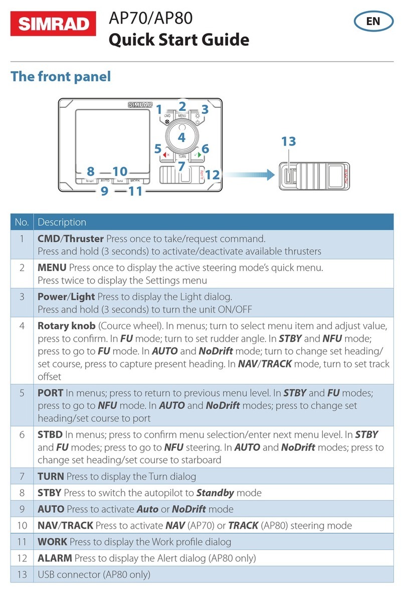
Simrad AP70 User manual

Simrad

Simrad AP70 User manual

Simrad ES80 User manual

Simrad

Simrad ES80 User manual

Simrad IS20 Combi User manual

Simrad

Simrad IS20 Combi User manual

Simrad EM - TECHNICAL NOTE 2000 User manual

Simrad

Simrad EM - TECHNICAL NOTE 2000 User manual

Simrad SN90 User manual

Simrad

Simrad SN90 User manual

Simrad ITI - INSTALLATION REV C User manual

Simrad

Simrad ITI - INSTALLATION REV C User manual

Simrad AP70 User manual

Simrad

Simrad AP70 User manual

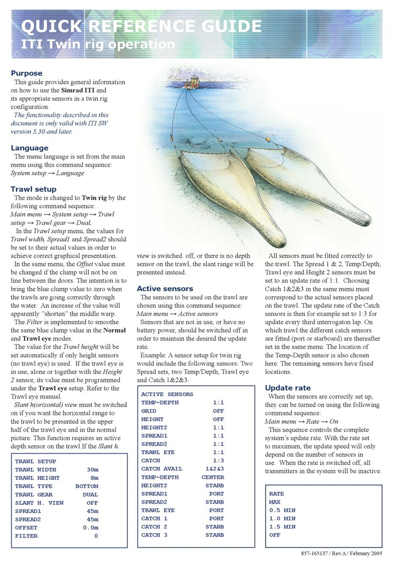
Simrad ITI TWIN RIG - QUICK REFERENCE GUIDE REV A User manual

Simrad

Simrad ITI TWIN RIG - QUICK REFERENCE GUIDE REV A User manual

Popular Marine Equipment manuals by other brands

POWERWINCH 825 Operation manual

POWERWINCH

POWERWINCH 825 Operation manual

JRC JLN-628 brochure

JRC

JRC JLN-628 brochure

DIGITAL YACHT PilotLink2 Product handbook

DIGITAL YACHT

DIGITAL YACHT PilotLink2 Product handbook

Clarion CMS2 Owner's manual & installation manual

Clarion

Clarion CMS2 Owner's manual & installation manual

EBS M7000 installation manual

EBS

EBS M7000 installation manual

Kongsberg M3 Bathy installation manual

Kongsberg

Kongsberg M3 Bathy installation manual

NPK SCS-1002 operating manual

NPK

NPK SCS-1002 operating manual

Furuno FE-800 installation manual

Furuno

Furuno FE-800 installation manual

Harken 1561 instructions

Harken

Harken 1561 instructions

Notifier FS-BSO Installation and maintenance instructions

Notifier

Notifier FS-BSO Installation and maintenance instructions

Raymarine ST40 Quick reference guide

Raymarine

Raymarine ST40 Quick reference guide

Raymarine Maxiview ST80 Owner's handbook

Raymarine

Raymarine Maxiview ST80 Owner's handbook

E2S E2XS112UL Instructions/service manual

E2S

E2S E2XS112UL Instructions/service manual

GUIDANCE MARINE 20- Series Installer's guide

GUIDANCE MARINE

GUIDANCE MARINE 20- Series Installer's guide

R2Sonic 2026 Operation manual

R2Sonic

R2Sonic 2026 Operation manual

COBHAM SAILOR 6000 installation manual

COBHAM

COBHAM SAILOR 6000 installation manual

Raymarine ST60 Tridata Owner's handbook

Raymarine

Raymarine ST60 Tridata Owner's handbook

Furuno Navtex NX-700-A Operator's manual

Furuno

Furuno Navtex NX-700-A Operator's manual

manuals.online logo
manuals.online logoBrands
  • About & Mission
  • Contact us
  • Privacy Policy
  • Terms and Conditions

Copyright 2025 Manuals.Online. All Rights Reserved.

21 4
65
3
MOUNTING: NAC-1
MOUNTING: Precision-9 7
Without bracket
With bracket
32
1
Outboard and
DrivePilot
Installation Guide
ENGLISH
NAC-1
Operating temperature -25 °C to +55 °C (13 °F to 131 °F)
Protection Splashproof, IPx5
Weight 0.6 kg (1.3 lbs)
Power supply/Load 9-16 V DC/140 mA + drive unit load
Performance Drive: 8 A cont., 16 A for 1 s
Pump-1
Operating temperature -15 °C to +75 °C (5 °F to 167 °F)
Protection Splashproof, IPx5
Weight 2.2 kg (4.9 lbs)
Hydraulic thread size 1/4 NPT
Load 5 A at 8 bar (116 psi), 7 A at 24 bar (350 psi)
Performance 0.8 l/min at 24 bar (350 psi)
Point-1AP
Operating temperature -25 °C to +60 °C (13 °F to 140 °F)
Protection Watertight, IPx7
Weight 0.14 kg (0.31 lbs)
Power supply/Load 9-16 V DC/<100 mA @ 12 V DC
Performance Heading: +/- 3°, Horiz. accuracy: 3 m (9.8 ft)
Compass safe distance 1 m (3.3 ft)
Auto/Stby Button
Operating temperature -25 °C to +55 °C (13 °F to 131 °F)
Protection Splashproof, IPx5
Weight 0.04 kg (0.09 lbs) (including cable)
Precision-9
Operating temperature -25 to + 65 °C (-13 to + 149 °F)
Protection IPx7
Weight 165 g (5.8 oz) + 130 g (4.6 oz) (Bracket)
Power supply/Load 8-16 V/1.4 W
Accuracy ± 2 degrees after calibration
Compass safe distance 0.5 m (1.7 ft)
PLANNING: Pump-1, Mounting location
CORRECT
FLUID LEVEL
PLANNING: DimensionsTechnical specications
PLANNING: Cable lengths
Screwdriver
Drill
Wrench
Cup or can
Tape
Tools to connect power cables to the battery
Gloves (disposable type)
PLANNING: Tools needed
Refer to“WIRING: Wiring diagram” (point 9) to nd the
various cable lengths.
PLANNING: Point-1AP and Precision-9 Compass,
Mounting location
Point-1AP and Precision-9
The compasses contain a magnetic heading sensor and should not
be mounted close to any potential magnetic source, and as close
to the vessel’s centre of roll and pitch as possible. Refer to technical
specications.
Potential sources for magnetic/electromagnetic interference include:
•Electrical Motors/Magnets/Moving Metal items
•Outboard Engines
•High current electrical sources such as main power cables,
batteries, distribution panels etc.
The Point-1AP compass also comes with a GPS antenna and should
be mounted as far as possible away from disturbing magnetic/
electromagnetic interferences.
Electromagnetic Interference Precision-9
57 mm
(2.2”)
180 mm
(7.1”)
190 mm
(7.5”)
204 mm (8.1”)
183 mm (7.2”)
91 mm
(3.6”)
169 mm (6.63”)
ø 90 mm (3.5”)
38 mm
(1.5”)
155 mm (6.1”)
76 mm (3.0”)
85 mm
(3.4”)
100 mm (4.0”)
85 mm (3.4”)
119 mm (4.69”)
36 mm
(1.42”)
119 mm (4.69”)
90 mm
(3.54”)
126 mm
(4.96”)
133 mm (5.23”)
119 mm (4.69”)
126 mm
(4.96”) 72 mm
(2.83”)
90 mm
(3.54”)
Compatibility information
The hydraulic kit comes with both 1/4 NPT 9/16 UNF ttings and ORB
ttings which make them ideally suited for the following steering
systems:
•Teleex SeaStar HC5345, HC5347, HC5348, HC5358.
•Teleex BayStar HC4600, HC4645, HC4647, HC4648, HC4658.
•Hynautic K6 Steering Rams
•Steering rams from Vetus, Uex, and Lecomble & Schmitt can also
be used.
¼Note: Newer SeaStar/BayStar helm pumps require the use of ORB
ttings (supplied in the kit).
8
MOUNTING: Point-1AP
A
C
B1 * Ø 19 mm (0.75”)
2 * Ø 3 mm (0.12”)
Note the mounting
direction!
D
1 2
3 4
Check the contents
•NAC-1 Autopilot computer
•Point-1AP or Precision-9 Compass
•Auto/Stby Button
•NMEA 2000 Network kit
•Pump-1
•Pump tting kit
Point-1AP
WIRING: Wiring diagram
14
9
15 16
Switch the autopilot to Power Steer mode.
Press and hold the arrow keys on the Autopilot controller in steps less
than 3 seconds at a time, until the cylinder reaches max travel in both
directions. The screenshots above are examples from HDS and NSS
evo2.
Continue to run the pump in both directions until no air bubbles are
left in the transparent tube.
IMPORTANT: Check uid level
MOUNTING: Bleeding the hand steering
Turn the wheel until the cylinder reaches max travel in both directions,
and rell oil.
Keep turning and relling oil until the oil level is stable and the
outboard engine responds rmly.
If air bubbles still remain in the system, follow the bleeding procedure
described for the outboard cylinder.
¼Note: It is recommended to use a threaded ller tube if available.
MOUNTING: Bleeding Pump-1
CORRECT
FLUID LEVEL
12
MOUNTING: Identify Type of Fitting Required
PORT
STB
STB
PORT
IMPORTANT: TRANSPARENT HOSE
+
_
12 V DC
MAIN
POWER
SWITCH
0.9 m (3 ft)
FUSE,
20 AMP 2 m (6 ft)
1 m (3 ft)
2 m
(3 ft)
5 m
(15 ft)
0.6 m
(2 ft)
1.8 m (6 ft)
T T
3 AMP
AUTO/STBY
BUTTON
POINT-1AP 1.2 m (4 ft)
Precision-9 4.5 mm (15 ft)
POINT-1AP
RED
BLACK
YELLOW
BLUE
Precision-9
ECHO
VIDEOIN
NMEA2K
NETWORK
POWER
ECHO
VIDEOIN
NMEA2K
NETWORK
POWER
PORT
13
MOUNTING: Pump-1, Connect hoses
IMPORTANT: TRANSPARENT HOSE
Conguration
Compliance Statements
Refer to your Autopilot controller’s documentation for setup
instructions.
The Outboard and the DrivePilot:
•Comply with CE under EMC directive 2004/108/EC
•Comply with the requirements of level 2 devices of the
Radiocommunications (Electromagnetic Compatibility) standard
17
11
MOUNTING: Disconnecting the hoses from helm
pump
1
2
3
STB
PORT
10
Installing with optional Verado tting kit for
Pump-1
310 mm
930 mm
VERADO STEERING
CYLINDER VOLUME
APPROX. 9ci - 150 cc
VERADO ELECTRO
HYDRAULIC POWER PACK
VERADO HELM
HIGH PRESSURE
STEERING LINES
LOW PRESSURE
RETURN LINE
HIGH PRESSURE
SUPPLY LINE
RETURN LINE
EXTENSION
HIGH PRESSURE
SUPPLY LINE
HIGH PRESSURE
STEERING LINES
STEERING LINES
RETURN LINE
LOW PRESSURE
RETURN LINE
STEERING LINE
EXTENSION
STB
ORB Fittings
NPT Fittings
DO NOT USE NPT FITTINGS
The drawing shows a SeaStar helm pump which identies ttings using
text engraved on the back.
¼Note: Helm and ttings required may vary by manufacturer.
¼Note: ORB and NPT tting kits are supplied in separate bags. Discard
the ttings not used.
¼Note: Pay attention to the ports on the helm pump to ensure you are
using the correct ttings.
MOUNTING: Connect hoses to helm pump
Check all ttings for leaks.
Shop for other marine electronics & navigation on our website.