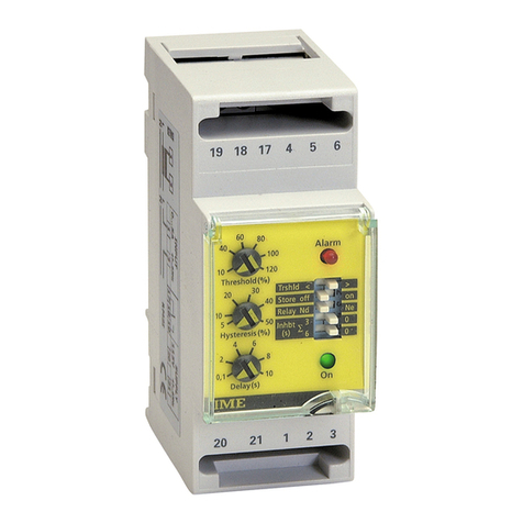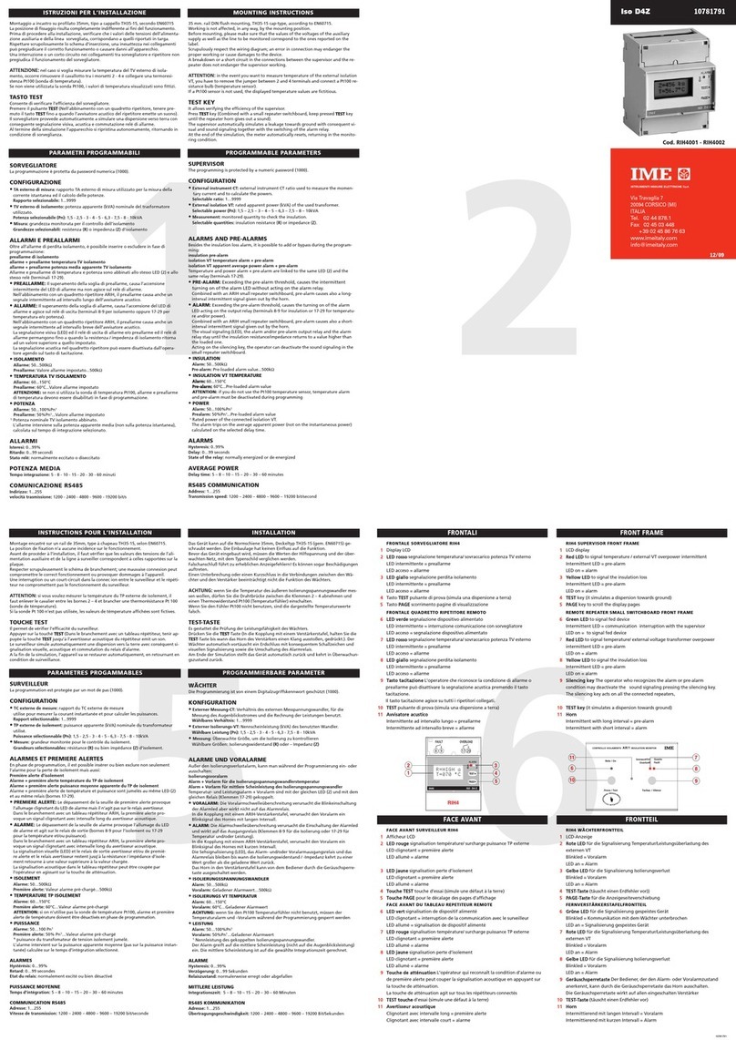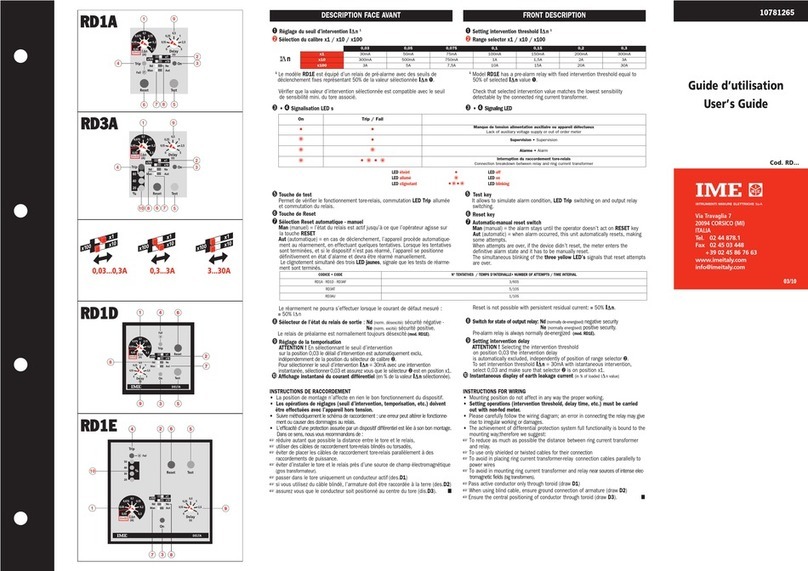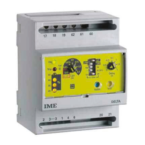
DESCRIZIONE FRONTALE
1) Predisposizione I∆n soglia d’ intervento
2) Predisposizione ritardo intervento
3) Segnalazione apparecchio alimentato (LED verde)
4) Segnalazione intervenuto allarme (LED rosso)
5) Pulsante di prova
6) Pulsante di ripristino
PREDISPOSIZIONE
Operazioni da effettuare con apparecchio non alimentato.
☞ Rimuovere il frontale
☞ Predisporre la soglia di intervento, secondo il valore di
I∆n desiderato.
PREALLARME
Punto di intervento: fisso, 50% del valore I∆n impostato
Tempo di intervento: ≤1s
ATTENZIONE:
per predisporre il valore e il tempo di intervento occorre, uti-
lizzando un cacciavite di dimensione appropriata, premere il
commutatore e quindi ruotarlo fino alla posizione desiderata.
☞ Controllare che il valore di intervento selezionato sia
compatibile con la sensibilità minima rilevabile da
trasformatore toroidale abbinato.
☞ Predisporre l'eventuale ritardo sull'intervento.
☞ Verificare che il valore della tensione di alimentazione
l’ausiliaria corrisponda con quelli riportati in targa.
DELTA RD1GP é fornito per funzionamento in sicurezza
negativa (relè normalmente diseccitato).
ISTRUZIONI DI MONTAGGIO
La posizione di fissaggio risulta completamente indifferente
ai fini del funzionamento.
☞ Incasso: foratura pannello e fissaggio secondo disegno
ISTRUZIONI DI CABLAGGIO
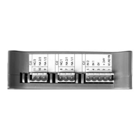
Rispettare scrupolosamente lo schema d'inserzione, una
inesattezza nei collegamenti è inevitabilmente causa di
funzionamento anomalo o di danni all'apparecchio.
L'ottenimento della piena funzionalità del sistema di prote-
zione differenziale è legato alle modalità di installazione,
per cui si consiglia:
☞ Ridurre al minimo la distanza tra toroide e relè
☞ Utilizzare cavi schermati o intrecciati per la loro connes-
sione
☞ Evitare di disporre i cavetti di connessione toroide-relè
parallelamente a conduttori di potenza
☞ Evitare di installare toroide e relè in prossimità di
sorgenti di campi elettromagnetici intensi (grossi trasformatori)
☞ Solo i conduttori attivi attraversano il toroide (dis.D1)
☞ Utilizzando cavo schermato, l’ armatura deve essere
collegata a terra come da (dis. D2)
☞ I conduttori devono essere posizionati al centro
del toroide (dis. D3).
ATTENTION:
to set the value and the intervention time it is necessary,
using an adequate screw-driver, press the switch and turn it
until it reaches the desired position.
☞ Check that selected intervention value is compatible with
the lowest sensitivity that can be detected from the
coupled ring current transformer.
☞ Setting the intervention delay
☞ Check that supply voltage meets the value shown on
the label.
DELTA RD1GP is supplied to work with negative security
(normally de-energised relay)
MOUNTING INSTRUCTIONS
Mounting position do not affect in any way the proper working.
☞ Flush mounting: panel cut-out and mounting according to the
drawing
FRONT DESCRIPTION
1) Setting intervention threshold I∆n
2) Setting intervention delay
3) Green LED for fed meter
4) Red LED for an occurred alarm
5) Test key
6) Reset key
SETTING
Operations to be carried out with the relay off.
☞ Remove the front frame
☞ Setting the intervention threshold according to I∆n
required value.
PRE-ALARM
Intervention point: fixed, 50% of loaded I∆n value
Intervention time: ≤1s
NUCLEO CHIUSO / CLOSED CORE
CODICE PASSAGGIO CAVO I∆n min(1) Imax(2)
CODE PASSING CABLE A A
TDGA2 Ø 28 0,03 80
TDGB2 Ø 35 0,03 200
TDGC2 Ø 80 0,03 300
TDGD2 Ø 110 0,1 600
TDGE2 Ø 140 0,3 1200
TDGF2 Ø 210 0,3 1800
DD11DD22DD33
NUCLEO APRIBILE / OPEN CORE
CODICE PASSAGGIO CAVO I∆n min(1) Imax(2)
CODE PASSING CABLE AA
TDAA2 Ø 110 0,5 600
TDAB2 Ø 150 0,5 1200
TDAC2 Ø 300 1 2000
(1) Minima corrente I∆n valore minimo di I∆n impostabile sul relè differenziale abbinato al toroide
I∆n lowest current I∆n lowest value that can be set on earth leakage relay connected with toroid
(2) Corrente di test corrispondente a 6In: Imax
Test current corresponding to 6In: Imax
INSTRUCTIONS FOR WIRING
Please carefully follow the wiring diagram; an error in
connecting the relay may give rise to irregular working or
damages.
The achievement of differential protection system full
functionality is bound to the mounting way; therefore we
suggest:
☞ to reduce as much as possible the distance between
ring current transformer and relay
☞ to use only shielded or twisted cables for their connection
☞ to avoid in placing ring current transformer-relay
connection cables parallelly to power wires
☞ to avoid in mounting ring current transformer and relay
near sources of intense electromagnetic fields (big transformers)
☞Pass active conductor only through toroid (draw D1)
☞ When using blind cable, ensure ground connection of
armature (draw D2)
☞Ensure the central positioning of conductor
through toroid (draw D3).
