PZE X4VP8
Operating Manual PZE X4VP8
1003206-EN-08 8
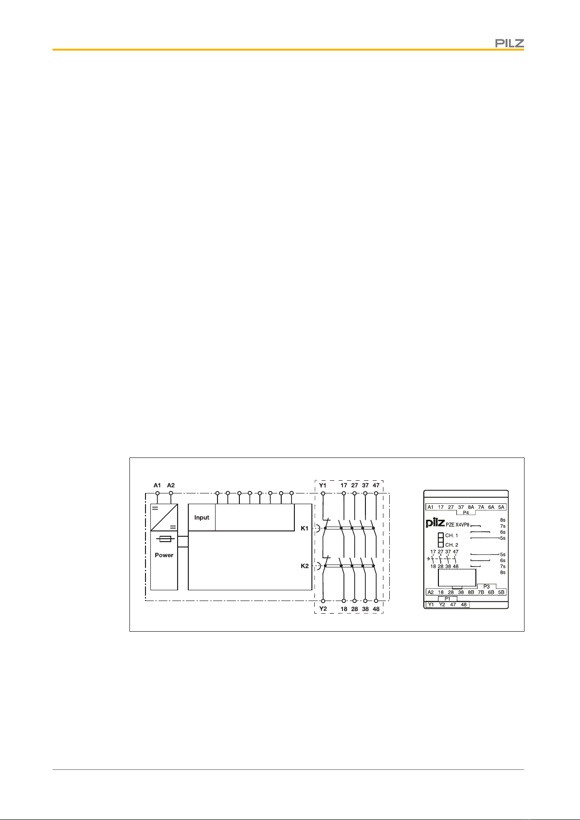
Function description
The contact expansion module PZE X4VP8 is an add-on device with selectable delay-on
de-energisation, and it is used to expand a safety circuit. The contact expansion module is
driven by a base unit (e. g. emergency stop relay).
}Functional procedure once the input circuit is closed (e.g. safety contacts on the base
unit are closed):
– The supply voltage is present at input (A1) of the contact expansion module.
– The safety contacts 17-18, 27-28, 37-38 and 47-48 close.
– The LEDs "CH.1" and "CH.2" are lit.
}Functional procedure once the input circuit is opened (e.g. safety contacts on the base
unit are opened):
– The supply voltage is not present at input (A1) of the contact expansion module.
– The LEDs "CH.1" and "CH.2" go out.
– Safety contacts 17-18, 27-28, 37-38 and 47-48 are opened redundantly once the
delay time has elapsed.
NOTICE
At the latest the safety contacts open after the set delay time tv + 50% of the
set value, even in the case of a component failure.
Installation
}The unit should be installed in a control cabinet with a protection type of at least IP54.
}Use the notch on the rear of the unit to attach it to a DIN rail.
}Ensure the unit is mounted securely on a vertical DIN rail (35 mm) by using a fixing ele-
ment (e.g. retaining bracket or an end angle).
Wiring
Please note:
}Information given in the "Technical details [ 11]" must be followed.
}Outputs 17-18, 27-28, 37-38 and 47-48 are delay-on de-energisation safety contacts.
}To prevent contact welding, a fuse should be connected before the output contacts (see
Technical details [ 11]).
}Calculation of the max. cable runs lmax in the input circuit:
Rlmax = max. overall cable resistance (see Technical details [ 11])
Rl/km = cable resistance/km
}Use copper wire that can withstand 60/75°C.
}Sufficient fuse protection must be provided on all output contacts with capacitive and in-
ductive loads.