IMER USA MASONRY 350 F 1188792 User manual
U.S.A. inc.
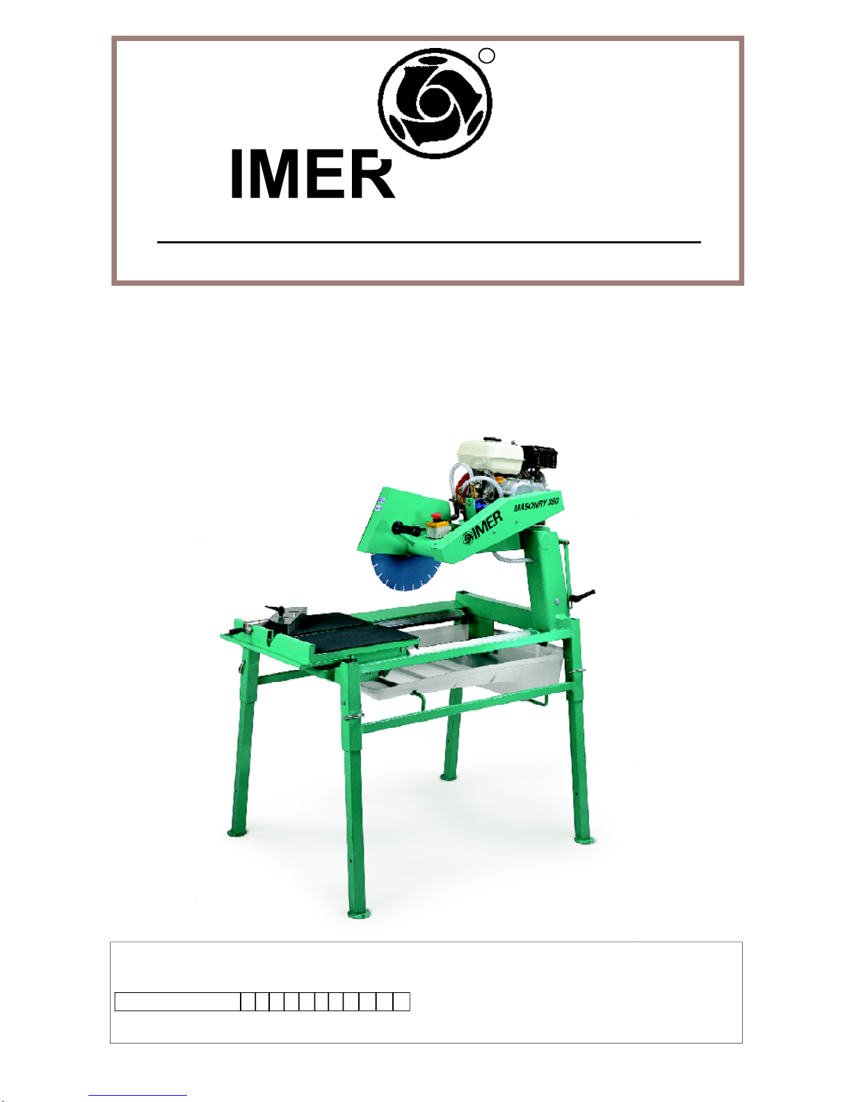
MASONRY 350F Sawing machine
R
MANUAL INSTRUCTION
and
PARTS LIST
Model - 1188792
Machine serial N°
Manual Part. number 3210296 - 05/2002
Write in the serial n° of your machine here

2
MASONRY 350 F
IMER INTERNATIONAL S.p.A.
Thank-you for purchasing a Masonry 350F from an Imer U.S.A. dealer. Your decision is an intelligent one.
There is no other sawing machine in the world which delivers the benefits and features of the Masonry 350F:
- Extremely rigid, mig welded bar steel frame.
- 5.5 H.P. Honda engine.
.- Compact design for easy trasportation.
- Extremely rigid worktable for a precise cutting.
At IMER U.S.A. we continually search for ways to better serve our customers. Should you have an idea or thought to
share with us regarding this product we would appreciate hearing from you. Our motto is "Tools and Services for the
21st Century" . We look forward to delivering the goods.
Thank you again for your purchase.
Mace T. Coleman, Jr.
President, Imer U.S.A, Inc.
IMERWEST
207 Lawrence Avenue
So. San Francisco, CA 94080
Tel 650 - 872 - 2200
Fax 650 - 873 - 6482 IMEREAST
221 Westhampton Place
Capitol Heights, MD 20743
Tel 301 - 336 - 3700
Fax 301 - 336 - 6681
1
2
3
4
5
6
7
8
9
10
11
12
Fig. 1
13
14
15
16
17
1. Telescopic leg
2. Spray guard
3. Engine
4. Blade support
5. Water pump
6. Guide
7. Emergency switch
8. Worktable
9. Water tank
10. Blade cover
11. Support locking handle
12. Work piece
13. Blade
14. Frame
15. Earth screw
16. Blade guard
17. Accelerator lever
3
MASONRY 350 F
IMER INTERNATIONAL S.p.A.
Dear Customer,
Congratulations on your choice of purchase: this IMER saw, the
result of years of experience, is a fully reliable machine and is
equipped with the latest technical innovations.
- WORKING IN SAFETY
Please read this manual before beginning to assemble or
operate this piece of equipment.
-ThisOPERATIONANDMAINTENANCEmanualmustbekeptonsite
bythe person in charge, e.g. the SITE FOREMAN, and must always
be available for consultation.
-Thismanual isto beconsideredanintegralpartofthemachine,and it
must be preserved for future reference (EN292/2) throughout the
machine’s normal working life. If the manual is damaged or lost, a
replacement may be requested from the saw manufacturer.
- The manual contains important information regarding site
preparation, installation, machine use, maintenance procedures
and requests for spare parts. Nevertheless, the installer and the
operator must both have adequate experience and knowledge
of the machine prior to use.
- To guarantee complete safety of the operator, safe operation
and long life of equipment, follow the instructions in this manual
carefully, and observe all safety standards currently in force for
the prevention of accidents at work. Use personal protection
(safety footwear, suitable clothing, gloves, goggles, etc.).
- Safety glasses or a protective visor must be worn at all
times.
- Ear protection must be worn at all times.
- MAKE SURE THAT WARNING SIGNS ARE ALWAYS
LEGIBLE.
- It is strictly forbidden to carry out any form of
modification to the steel structure or working parts of the
machine.
-IMERINTERNATIONALdeclinesallresponsibilityfornon-compliance
with laws and standards governing the use of this equipment, in
particular; improper use, defective power supply, lack of
maintenance, unauthorised modifications, and partial or total failure
to observe the instructions contained in this manual.
IMERINTERNATIONALisentitledtomodifythecharacteristicsofthe
sawing machine and/or the contents of this manual without
necessarily updating previous machines and/or manuals.
1. TECHNICAL DATA
Table 1 shows the saw’s technical data, referring to figure 1.
2. DESIGN STANDARDS
MASONRY 350 F saws are designed and manufactured according
to the following standards: EN 292-1-2; EN 12418.
3. NOISE EMISSION LEVEL
Table2indicatestheenvironmentalnoiselevelsmeasuredforthepanel
saw (lwa) in accordance with EN ISO 3744 and the acoustic pressure
level measured at the operator’s ear with the machine empty (Lpa).
TABLE 2-[dB(A)]
SAWINGMACHINE TYPEOFMOTOR LPALWA
Masonry350FENG HONDAGX160K1(Hp5.5) 95 107
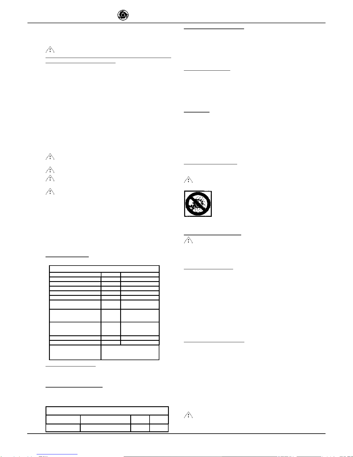
4. CUTTING SPECIFICATIONS
This saw model has been specially designed for cutting stone,
ceramics,marble,granite,concreteandsimilarmaterials.Onlywater-
cooled diamond blades with continuous or segmented edges (see
paragraph 13) must be used. Under no circumstances must dry
cutting blades be used or materials other than those specified above.
IMERINTERNATIONALdeclinesallresponsibilityfordamagecaused
byimproper use of the above machine.
5. CUTTING CAPACITY
- max. cutting capacity with vertical blade = 5 " in. one single pass.
- max. height of workpiece: 9" in. in two passes.
- min. width of workpiece: 2" in.
- max. cutting length: 18" in. (with blade lowered), 21" in (with blade
fully raised).
-Blade at 45°: with support at 45° on the work surface.
6. WARNING
- Do not load the saw with workpieces that exceed the specified
weight (max. 90 lb.)
- Ensure stability of machine: it must be installed on a solid base with
a maximum slope of 5° (fig. 2).
- Ensure the workpiece is stable before, during and after cutting: in
any case, workpieces must not overhang the worktable.
- Respect the environment; use suitable receptacles for collection of
cooling water contaminated with cutting dust.
7. SAFETY PRECAUTIONS
- IMER saws are designed for work on construction sites and under
conditionsofnaturallight,hencetheworkplacemustbeadequatelylit.
- The machine must never be used in environments subject
to risks of explosion and/or underground sites
- IMER saws may only be used when fitted with all
required safety devices, which must be in perfect
condition.
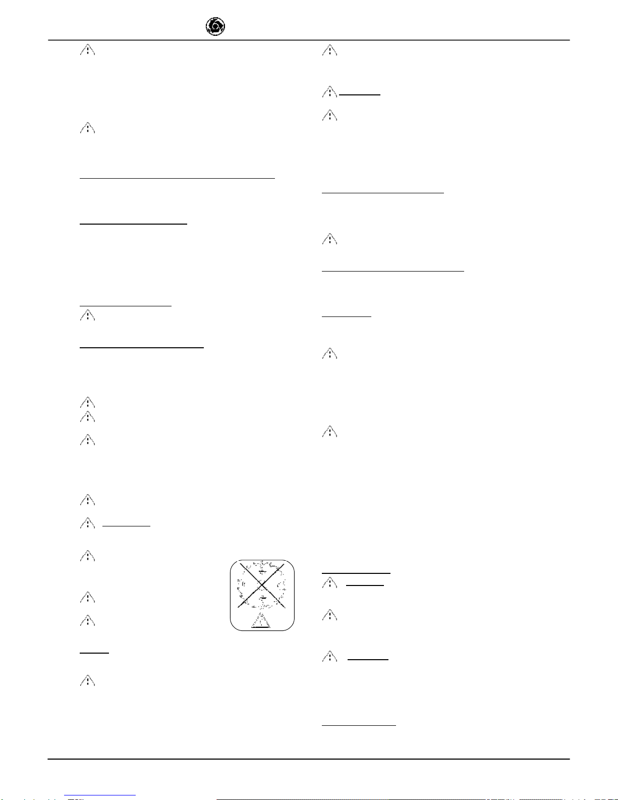
- The symbol shown on the label (fig. 3) indicates the
warning“ENSUREALLPROTECTIONDEVICESARE
INSTALLEDANDINPERFECTCONDITIONBEFORE
SWITCHINGONTHEMACHINE”.
8. TRANSPORTATION (fig.4)
- WARNING Lock blade support arm by means of the
relative handle before moving the saw (ref. 11, fig. 1). To
transport the machine use slinging equipment with 4 rope
legs, fixing the hooks to the relative attachments (fig. 4).
9. INSTALLATION (fig. 4)
- Lift the machine out of its package using slinging equipment with 4
rope legs. Fix the hooks to the relative attachments.
- Unlock thelegs by sliding out the splitpins (ref.1).
-Lock thelegsatworkingheight.Refitthepinsinthelegsupportsand
insert the split pins.
- Install the machine on a completely even and stable surface.
- Release the carriage from the lever that secures it to the frame.
– Fill the pump with water, unscrewing the connector (fig.10).
Wheninstallingonsite itisgoodpracticetoconnectthemachine’s
metal structure to the earthing system by means of the screw
(fig.1 ref.15) using an earthing braid (or cable) with a minimum
cross-section of 16 mm2.
10. STARTING THE MACHINE.
The endothermic motor is equipped with a centrifugal clutch which
engages automatically, transmitting drive to the cutting wheel as the
engine revs up.
The hazard warnings and the instructions for use and maintenance
contained in the manual enclosed with the endothermic engine must
be read and understood before the engine is started.
1-Check the engine (see enclosed engine manual).
2-Check the oil level in the motor; horizontal motor position (see
enclosed motor manual).
3-Fill the fuel tank (enclosed engine manual).
4-Set the accelerator lever to minimum, so as to start the motor
without turning the cutting wheel (clutch not engaged).
5-Warm the engine by letting it run at low speed
- Emergency-stop: press the engine stop button (ref. 7,
fig. 1), (turn to switch on again).
Keep far enough away from the saw when it is running to avoid
inhaling exhaust gases from the endothermic engine.
Fig. 3
TABLE 1 - TECHNICAL DATA
Blade rpm rpm 2.450
Blade diameter in. 14"
Blade mounting hole in. 1"
Engine type Honda GX 160
Power engine Hp 5.5 / 3.600 rpm
Motor rpm rpm 3.400
Cutting table dimension in. 20" x 17"
Overall dimensions
(widthxlengthxheight) in. 34" x 47" x 58"
Overall dimensions for
transport
(widthxlengthxheight) in. 33" x 50" x 46"
Weight lb. 250
Weight for transport lb. 300
Blade rotation direction(seen
from blade clamping flange) CLOCK WISE
4
MASONRY 350 F
IMER INTERNATIONAL S.p.A.
- Turn off the engine before topping up the tank with
petrol.
Saws with endothermic engines must be used in the open air. If
they have to be used in closed environments, the openings must
be provided to conduct gases from the engine’s exhaust pipe to
the outside using appropriate non-flammable flexible tubes.
These mustbe checked for leaks and breakages atthe beginning
of every shift.
- Do not start the machine with the blade in the
workpiece.
When the saw is not being used, turn the petrol cock to the OFF
position.
10.1 STARTING ROTATION OF THE CUTTING WHEEL.
Gradually move the lever (ref.17; fig.1) so as to bring the motor
revs up to normal working speed and start the wheel turning at
the cutting speed foreseen.
11. STARTING THE MACHINE
Before cutting:
1 – Check that there is enough cooling water in the tank.
2 - adjust the flow of cooling water by turning the cock next to the
blade guard (do not perform cutting without water).
3 - Ensure that blade rotation corresponds to the indications on
the blade guard.
4 – If everything is in order, work can begin.
12. EMERGENCY - STOP
- In an emergency, stop the machine by pressing the
stop control switch (ref. 7, fig. 1).
13. BLADE INSTALLATION (Fig.5)
By means of a hex wrench no.10, unscrew the 3 screws that
lock the moving blade guard (ref.3). Use a hex wrench no. 13 to
remove the screw that locks the flanges on the disc: this screw
has a left-hand thread (rif.1). Remove the mobile flange (rif.2)
and check thatthe flanges,disc shaft and blade are not damaged.
- Never use worn blades or blades with missing segments.
- Only use blades that are designed for the number of
revolutions indicated on the machine rating plate.
- Check that blade rotation corresponds to that
indicated on the blade guard.
Centre the blade against the fixed flange, position the mobile
flange and tighten the securing screw by means of a hex
wrench no. 13 (turn clockwise). Refit the moving blade guard,
tightening the 3 screws (ref.3).
- Ensure that the blade guard (ref.3) is locked
securely into position.
- WARNING! An incorrectly installed blade, or a
screw insufficiently tightened can provoke damage to
the machine or injury to persons.
- Note that the blade must have
an external diameter of 14"in. , a
central hole diameter of 1" in. and max.
thickness of 1/8" in..
- Check that the blade to be used
is suitable for the material to be cut.
- Do not use blades for wood!
(fig. 6).
14. USE
- Leave a space of at least 5 ft. around the machine to operate
in full safety.
- Do not allow other persons to approach the
machine during cutting.
- Never use the machine in fire-risk areas. Sparks can cause
fire or explosions.
- Make sure that the machine is switched off before positioning
or handling.
- Always ensure that the blade is free of any contact before start-up.
- Ensure correct installation of all protective devices.
- Before starting work, fill the water tank. Top up during operation
whenevernecessary:N.B.thepumpsuctionhosemustalwaysremain
immersed in water.
- WARNING! For safety purposes the removal of protective
guards from the machine is strictly prohibited.
- WARNING! Always switch off the machine before
carrying out blade adjustment.
Loading and unloading pieces on the machine cutting table.
To avoid the risk of accidental contact with the cutting wheel, the
pieces must be positioned and removed from the carriage with the
cuttingwheelstopped. Thisisdonebyadjustingthelever(ref.17;fig.1)
so as to reduce the revs to minimum,thus disengaging the clutch.
14.1 VERTICAL BLADE MOVEMENT
Toraiseorlowertheblade,slackenthe supportlockinghandleturning
it anti-clockwise (ref. 11, fig. 1). The blade support remains free to
rotate, so it can be secured in the desired position, fully tightening the
handle (ref. 11, fig. 1).
- Ensure that the locking handle is tightened fully before
starting work.
14.2 BLADE POSITIONING FOR 45° CUTS
To make a cut at 45° the 45° support on the carriage is necessary.
Once the workpiece is correctly positioned, cutting can begin, starting
the endothermic engine.
14.3 CUTTING
Forsafe use of the machine when cutting, push the carriage forwards
as the cut advances, placing your hands to the two sides of the
carriage. Never push directly on the piece to be cut.
- Check that the blade is aligned with the cutting line.
- Place the workpiece on the worktable (ref. 8, fig. 1), resting firmly
against the stop.
- Start the engine.
- Wait until the water reaches the blade.
- Begin cutting.
- Horizontal cutting movement is carried out by pulling the carriage
towards the blade.
- As cutting thickness increases, the blade is subjected to
greater stress. To avoid overloading the engine, the operator
should continually check blade feed speed. The speed will
also depend on the characteristics of the material being cut
(hardness, toughness etc.).
14.3.1 CUTS WITH BLADE LOWERED FROM ABOVE
Bring the blade support to its highest position and lock. Position the
workpiece on the worktable. Start the machine and begin vertical
cuttinguntilthebladereachesitslowestpoint.Lockthesupportlocking
handle and proceed with horizontal cutting
14.3.2 BLADE CHANGE
To change the blade refer to section 13.
15. MAINTENANCE
- WARNING.. Servicing must always be carried out by
skilled personnel and only after the endothermic engine has
been turned off.
-Always keep the guards in proper working order and
free from damage.Take particular care to ensure that the
blade guards are kept efficient and clean, replacing them if
they are damaged.
- WARNING.. Recommended product for cleaning
mechanical parts: WD-40.
Do not leave the machine outside: it must always be protected from
the weather.
Belowisalistofthecleaningoperationsthatmustbecarriedoutatthe
end of every shift.
15.1 TANK CLEANING
Empty the tank by removing the drain plug. Remove cutting residue
using a jet of water.
Fig. 6

5
MASONRY 350 F
IMER INTERNATIONAL S.p.A.
15.2 TANK REMOVAL (Ref.Fig.7).
- Lift the tank (ref.1) to detach it from its supports (ref.2) and
remove it from the side indicated by the arrow.
15.3 WORK SURFACE CLEANING
Always keep work surfaces clean. Residual dirt can impair
cutting precision.
15.4 GUIDE RAIL CLEANING
It is good practice to remove all traces of dirt from the guides.
15.5 CLEANING AND MAINTENANCE OF COOLING
CIRCUIT
- If water does not reach the blade stop the machine immediately
to avoid blade damage.
- After switching off the machine ensure that the water level is
sufficient.
-Check that there is water in the pump by unscrewing the
connector, and if necessary top up until water flows out (fig.10).
- WARNING. Before starting the panel saw for the
first time, or when starting it after long periods of
inactivity, fill the pump with water as described above.
- At the end of every shift, unscrew the suction hose filter and
clean it. Then, circulate some water through it placing inside a
bucket of clean water.
15.6 TENSIONING THE DRIVE BELT (fig. 8)
- Turn off the endothermic engine.
- Unscrew the 4 screws that lock the movable belt guard (ref. 1).
- Loosen the two screws (ref. 2) that clamp the water pump to
the bracket and move the pulley away so that it does not touch it.
- Loosen the 4 screws (ref. 3) that clamp the endothermic
engine to the blade support.
- Tension the belt using the nut (ref. 4): apply a force of about
F=14 lb. to the centre of the free section of the belt, the arrow
should be about f=1/4" in. (fig. 9).
- Tighten the screws on the endothermic engine, checking the
alignment of the engine pulley and the blade pulley
- Lower the water pump until the pulley touches the drive belt.
Tighten the two screws.
- Refit the guard and lock it using the 4 screws.
- To avoid shortening the life of the belt, the bearings
and the blade shaft, do not overtension the belt. Finally,
check the two pulleys are aligned.
15.7 DRIVE BELT REPLACEMENT
Repeat the operations described in section 15.6, replacing the
belt before tensioning it.
15.8 ENDOTHERMIC ENGINE MAINTENANCE
Read the Honda manual carefully... and follow their instructions.
Changing the oil (with the engine in horizontal position) and
cleaning the air filter frequently ensure a reliable and long lasting
engine.
When you may need Honda Engine Service or Warranty
Assistance take the machine to your local Honda power
equipment dealer, they will honour the Warranty throughout
America.
- It is always a good idea to check the oil level in the
engine cranckcase at the start of each working day.
Clean oil at the correct level markes for an engine that
will last and last.
15.9 REPAIRS
- Do not start the saw during repair work.
Only use genuine IMER spare parts and do not modify
them.
- If the guards are removed to carry out repairs,
they must be refitted properly when the repair work is
finished.
FAULT CAUSE REMEDY
Vertical blade
movement not
smooth
- locking knob too tight - Slacken knob
Horizontal carriage
movement not
smooth
- Guide rails dirty - Clean the guide rails
Lack of cooling water
supply to blade Refer to section 15.5: "cleaning and
maintenance of cooling circuit" (Chapter 15.5)
Blade does not cut
- Blade is worn
- Drive belt not
tensioned
- Fit newblade
-Tension the belt
Motor starts but
blade does not rotate Belt is broken Replace drive belt
16. TROUBLESHOOTING
- WARNING.. Stop the saw and turn off the
endothermic engine before carrying out any
maintenance.

6
MASONRY 350 F
IMER INTERNATIONAL S.p.A.
1
1
3
1
1
2
1
2
1
1
3
4
2
5° MAX
Fig. 2 Fig. 4
Fig. 5
Fig. 8
Fig. 7
Fig. 9
Fig. 10
UNSCREW

7
MASONRY 350 F
IMER INTERNATIONAL S.p.A.
TAV.1 - ASSEMBLY OF MOTOR
RIF. COD. GB NOTE
1 3210291 MOTOR HONDA GX 160
2 3210139 BELTS INTERNAL
COVER
3 3210148 BELTS EXTERNAL
COVER
4 3210185 BELT
5 3210159 PULLEY
6 2224190 WASHER 8X32 Z
7 2222076 BOLT M8X25 Z
8 2222176 BOLT M8X50 Z
9 2222004 BOLT M8X35 Z
10 2224140 WASHER 8X18 Z
11 2223923 SELF LOCKING
NUT M8 Z
12 3203921 BOLT M5X10 Z
13 2222021 BOLT M6X16 Z
TAV. 2
TAV. 3
TAV. 1
TAV.2 - WHEEL KIT
Rif. Cod. GB Note
1 2226700 SPLITPIN
2 2211150 WHEEL
3 3206261 LEFTTUBEGUIDE
4 3206262 RIGHTTUBEGUIDE
5 2222082 SCREW 5739 M10X60Z
6 2223650 DISK 5588M10Z
7 3206641 WASHER 659228X50X2Z
8 3206260 WHEELTUBE
TAV.2 - 45° SUPPORT
Rif. Cod. GB Note
1 2284859 KNOB

8
MASONRY 350 F
IMER INTERNATIONAL S.p.A.
TAV. 4 - MACHINE STRUCTURE
RIF. COD. GB NOTE
1 3208421 CARRIAGE
2 2222061 BOLT 5739 M 8X20 Z
3 2222515 BOLT 5931 M 8X16 Z
4 3204945 BEARING 608-2RS1
5 2223923 SELF LOCKING NUT M 8 Z
6 3207397 WHEEL
7 2222090 BOLT 5737 M 8x75 Z
8 3210193 GUIDE BAR
9 3208442 LEFT FENCE
ADHESIVE LABEL
10 3208441 RIGHT FENCE
ADHESIVE LABEL
11 3205581 RUBBER COAITING
12 2224612 WASHER D.21X43 Z
13 3206086 PIN
14 3201517 LEG
15 3210178 CUTTING HEAD
GROUP
16 3206096 SUPPORT
17 2223920 SELF LOCKING NUT M 10 Z
18 3201015 PLUG
19 2222587 SCREW 5933 M 8X20 Z
20 3210171 SPRAY GUARD
21 3210169 FRAME
22 3205526 WATER RUN-OFF
TRAY
23 2222425 SCREW AUTOFOR.TE 4,2X13
24 3204818 DRUM
25 2235428 PLUG
26 3210173 WATER PUMP
27 3210183 WATER FILTER
28 2224320 WASHER D.10X21X2
29 3210158 SHAFT
30 2209450 NYLON BUSHING
31 2222002 SCREW 5739 M 6x16 Z
32 2222059 SCREW 5739 M8X25 Z SX.
33 3208414 LEVER
34 3208422 GONIOMETER
35 3207213 GUIDE BAR
SUPPORT
36 3208428 TROLLEY SLIDE
37 3210236 GUIDE BAR
SUPPORT SX
38 2222580 SCREW M 4X20 Z
TAV. 4 - MACHINE STRUCTURE
RIF. COD. GB NOTE
39 3210153 ROTATION
ADJUSTING ROD
40 3209333 KNOB M 8 Z
41 3210297 TROLLEY CLAMPING
42 2222016 SCREW 5739 M 6x20 Z
43 2223924 NUT M 6 Z
44 3209332 CAM
45 2222018 SCREW 5931 M 8X35 Z
46 2224534 WASHER 6X12.5 Z
47 3210416 HOOSE JOINT 90°
1/4"
48 3210175 EMERGENCY
SWITCH
49 2288885 HANDGRIP
50 3206513 BEARING 6205 2RS
51 3210179 DISC COVER
52 3232759 OIL SEAL RING 35X52X7
53 3204777 INNER FLANGE
54 3204776 OUTER FLANGE
55 3210156 WATER HOSE
56 3210629 BEARING 6006 2RS
57 3205635 VALVE
58 3210140 BLADE COVER
59 2222006 SCREW M 8X30 Z
60 3210189 SELF LOCKING NUT M 20 Z
61 3210418 HOOSE JOINT 1/4"
62 3204889 LEVER
63 3210160 PULLEY
64 2224910 WASHER DEV. D.10 Z
65 3210142 BLADE GUARD
ROTATION ROD
66 3210152 SPRING
67 2227320 STOP RING E/20
68 3210181 SPRING PIN
69 3210206 SPRAY GUARD
70 3210149 TIE ROD SCREW
71 3210229 PUMP COVER SHEET
72 2226778 HOOSE JOINT F3/8
73 3210542 DISK PROTECTION DX
74 3210543 DISK PROTECTION SX
75 3210576 NYLON WASHER 8.4XX17X1.5
76 2224140 WASHER 8X18 Z.
77 2222110 SCREW 8X80 Z
TAV. 4

ONE YEAR WARRANTY
We warrant to the original purchaser that the IMER equipment described herein
(the "equipment") shall be free from defects in material and workmanship under
normal use and service for which it was intended for a period of one (1) year from
thedateofpurchasebytheoriginalpurchaser.
Our obbligation under thiswarranty is expressely limitedto replacing or repairing,
free of charge, F.O.B. our designated service facility, such part or parts of the
equipmentasourinspectionshalldisclosetobe defective.Partssuchasengines,
motors,pumps,valves,electricmotors,etc.furnishedbyusbutnotmanifacturedby
uswillcarryonlythewarrantyofthemanifacturer.Transportationchargesorduties
shallbeborneby thepurchaser.Thisshallbethelimitofourliabilitywithrespectto
thequalityoftheequipment.
This warranty shall not apply to any equipment, or parts thereof, which has been
damaged by reason of accident, negligence, unreasonable use, faulty repairs, or
which has not been mantained and operated in accordance with our printed
instructionsforourequipment.Further,thiswarrantyisvoidiftheequipment,orany
ofitscomponents,isaltered ormodified inanyway.
THIS WARRANTY IS EXPRESSLY IN LIEU OF ALL OTHER WARRANTIES,
EXPRESSED OR IMPLIED, INCLUDING ANY IMPLIED WARRANTY OF
MERCHANTABILITYOFFITNESSFORAPARTICULARPURPOSE.
Wemakenootherwarranty,representationorguarantee,norisanyoneauthorized
tomakeoneonourbehalf.Weshallnotbeliableforanyconsequentialdamageof
any kind, including loss or damage resulting, directly or indirectly, from the use or
loss of use of the machine. Without limiting the generality of the foregoing, this
exclusionfromliabilityembracesthepurchase'sexpensesfordowntime,damages
for which the purchaser may be liable toother persons, damages to property, and
injuryordeathofanypersons.
This warranty shall not be deemed to cover maintenance parts, including but not
limited to blades, belts, hoses, hydraulic oil or filters, for which we shall have no
responsabilityorliabilitywhatsoever.
IMERU.S.A.,Inc.
207LawrenceAvenue
SouthSanFancisco, California 94080
(650) 872-2200

This is a contact addendum to our manuals
Imer USA East
221 Westhampton Pl
Capitol Heights, MD 20743
Phone: 301-336-3700
Fax: 301-336-6687
Order Fax:301-336-5811
Imer USA West
3654 Enterprise Ave
Hayward, CA 94545
www.imerusa.com
800-275-5463
This manual suits for next models
1
Table of contents
Other IMER USA Saw manuals


