Bushton 214 User manual

Bushton Manufacturing
Maker Of
Hawk Woodworking Tools
MODEL 214 HAWK SCROLL SAW
OPERATORS MANUAL
J
.
I •
~
READ THOROUGHLY BEFORE
OPERATING
MANUAL #HA 0987

CONTENTS •••••••••••••••••••••••••••••••••••••••••••••••
ITEM PAGE NO.
SAFETY 3
SET-UPINSTRUCTIO S 3
BLADE SELECTION 10
MAINTENANCE 4
SAWINC TECHNIQUES 4, 5, 6
TROUBLE SHOOTINC 7
BLADE CHANCINC 8
TABLE ADJUSTMENTS 9
PARTSBREAKDOWN 10, 11
SPECIFICATIONS 12
ACCESSORIES 12
HOW TO ORDER PARTS 12
WARRANTy ••••••••••••••••••••••••••••••••••••••••••••••
We guarantee each Hawk Scroll Saw to be free from defects in material and workman-
ship for 1 year from date of delivery to original user. This warranty does not cover damage
sustained in transit or from misuse of this piece of equipment.
This warranty does not obligate us to bear the cost of labor or transportation charges in con-
nection with the replacement or repair of defective parts,
nor shall it apply to any saw upon
which repairs or alterations have been made unless authorized by us.
We make no warranty in respect to components, not of our manufacture, including motors,
such being subject to the warranties of their respective manufacturers.
We shall in no event be liable for consequential damages or contingent liabilities arising out
of the failure of any saw to operate properly.
No express, implied or statutory warranty other than herein set forth is made or authorized
to be made by us.
ENCLOSED WARRANTY REGISTRATION CARD
MUST BE RETURNED TO VALIDATE YOUR
WARRANTY.
TO VALIDATE WARRANTY, CUSTOMERS
Must mail in warranty card on receipt of machine.
2

TRAINING _
1. Read the operators manual carefully. Be
thoroughly familiar with the operation of the
equipment.
2. Know where the controls are and how to oper-
ate them.
3. Wear safety goggles, ear protection and mask
in dusty operations.
4. Never allow unsupervised children to operate
equipment. Never allow adults to operate the
equipment without proper instruction.
5. Keep work area clear of other persons.
6. Maintain a clean uncluttered work area.
OPERATION SAFETY _
1. Never make any adjustments while the
machine is running.
2 . Disconnect electrical power supply before do-
ing any adjustments on the machine.
3. Remove all working tools and equipment be-
fore starting machine.
4. Wear proper clothing. Avoid loose fitted cloth-
ing, long sleeves, long hair, gloves, neck ties,
jewelry, watches, rings, ete.
s.
Do not operate an electrical device in a damp
or wet area to avoid electrical shock.
6. Maintain all safety guards.
7. Do not operate machine while under the in-
fluence of medication, alcohol or drugs.
8. ever leave machine running unattended.
9. Don't overload machine. Follow operators in-
struction for safe operation.
1 O. Keep equipment in proper working order. Fol-
low recommended maintenance procedures
in the operators manual.
SETUP ••••••••••••
OTE: Damage and/or missing parts are to be
reported to the transportation carrier.
Manufacturer is not responsible for ship-
ping damage.
This saw is shipped complete in two cartons:
Carton 1 Carton 2
1. Saw 1. Legs
2. Operators manual 2. Glides (leg bottom)
3. Extra blades 3. Attaching hardware
1. Remove saw from shipping carton.
2. Check for damage.
3. Remove legs from carton.
4. Install one leg on each corner of the base us-
ing 1/4' carriage bolts and nuts. (The top of the
leg should be inside of the base.)
5. Install one 3/8" nut on each of the four glides.
6. Insert the glides up through the hole in the bot-
tom of the leg. (See Fig. 1)
7. Install the second 3/8" nut on the glide to
secure.
8. With all of the legs installed, position the saw
upright and adjust the nuts on the glides so
that each glide supports the saw.
~-.
1/4" NUT \-
'\
HAWK 214, FIG. 1
1/4" CARRIAGE ~
BOlT
3/8" NUT
BASE
LEG
- GLIDE
3
NOTE: Optional adjustable 6" leg extension is
available. Part #6LE (See Accessories)

MAINTENANCE _
Arm Pivot:
Add 3 to 4 drops of oil (light machine oil) to each side of
the parallel arm pivot point bushingson the upper and lower
arms every
16
hours.
Table:
Keep the table work surface waxed (paraffin wax) to pre-
vent oxidation and allow easier movement of the wood on
the table surface.
Tensioning Rod:
Add
1
to
2
drops of oil (light machine oil) to the threads
of the blade tensioning rod at the bottom arm every
16
hours.
Carn Over Handle:
Apply wax (paraffin wax) to sliding surface of handle to al-
low easier use.
OIL
OIL
FIG. 2, MAINTENANCE
SAWING TECHNIQUES
Starting:
It is best to begin the cut at a point or corner because it
isdifficult to smoothly blend in start and end points when start-
ing on a side. When cutting out circular shapes, saw into the
pattern line in a crosscutting (acrossthe grain) direction. If the
starting point must be on a curve, make it an outside curve.
Burrs and knobs are easier to sand on an outside curve.
Sawing:
Feed the piece to be cut slowly into the saw blade while
maintaining downward pressure on the piece. Do not force
it into the blade-let the saw blade do the work. The speed
at which you feed the wood into the blade depends on the
type of wood you are cutting. Harder woods should be fed
more slowly than softer varieties. Feeding too quickly into the
blade may result in the blade burning the wood, bending or
twisting of the blade while sawing, a rough edge on the cut,
or the wood jumping on the table. Do not apply sideways pres-
sure on the blade. The downward pressure on the wood may
be applied by hand or the hold down foot.
Straight-line Cutting:
A small amount of set isformed on one side of most scroll
saw blades due to the manufacturing process used to produce
them Because of this, most blades do not cut straight
or
parallel to the blade. The set causesthem to cut afew degrees
more to one side than the other. To saw a straight line, the
work should be angled approximately 2to 4degrees to com-
pensate for this. This may be accomplished freehand or with
a guide board. The same technique should be used for straight-
line ripping. Besure that the saw blade isfollowing the layout
line and not the grain when ripping. (See Fig. 3)
,.
FIG.3
4

Turns and Corners:
Scroll saws are capable of producing 360
0
turns
while cutting. The kerf left after a turn is approximately
1/2 the width of the saw blade. When you want to
cut a point, simply turn the piece the desired amount
while maintaining downward pressure on it. It is not
necessary to cut past the point and then restart, like
the normal procedure for a band saw. When cutting
curves, slowly follow the pattern line, turning the piece
as you go so the teeth are following the line. It may
be necessary to install a smaller blade when trying
to saw an extremely tight corner or radius to prevent
the wood from jumping on the table and to prevent
blade breakage. (See Fig.
4)
Bevel Sawing:
Bevel sawing is sawing with the table tilted, creat-
ing angled sides on the project. This sawing technique
may be used to create inlays, decorative letters, or
to put shapes into animals or other objects to be
carved. To bevel saw on the Hawk, loosen the table
tilt assembly knob and tilt the table to the desired
angle. (See Fig.
5)
Stack Cutting:
Stack cutting saves time by cutting two or more
pieces simultaneously. Simply stack the work pieces
on top of each other and draw the pattern on the
top piece. The pieces may be held together with dou-
ble faced tape or nails may be driven into the scrap
areas. Cut out the pattern on the top piece and dis-
assemble the stack. Be sure that the saw table is per-
fectly square with the blade before sawing. (SeeTable
Squaring Procedure) If it is not square, the pieces will
not be uniform in size. The stack should not exceed
2/1
in height. (See Fig. 6)
Sawing Inside Openings:
Sawing inside openings is a common and frequent-
ly used process on scroll saws. It is cutting an open-
ing on the inside of the work piece without cutting
through the piece. To do this, drill a small hole that
is large enough for the blade to pass through near
the pattern line of the inside openings. Release blade
tension by flipping the cam lock handle to the blade
change position. Remove top of blade from the top
blade holder (See Blade Changing). Insert the blade
through the drilled hole in the work piece. Install the
top of the saw blade back into the top blade
holder.Retension the blade by flipping the cam lock
handle to its original position. After the cut isfinished,
remove the blade from the opening. NOTE: Discon-
nect electrical power supply before making any ad-
justments to the machine. (See Fig. 7)
FIG. 5
FIG. 4
5

Compound Sawing:
The compound sawing process involves cutting on
two or more sides of the work piece. To do this, sim-
ply layout a pattern on two adjoining surfaces. These
patterns may be identical or different. After the pat-
terns are laid out, choose which surface to saw first.
It usually will not make any difference which surface
you choose, but consider the sequence before
choosing. The side that will give the least amount
of scrap pieces after it is cut should be first. After
the first side is cut, return the scrap pieces to their
original locations so that you have a prismatic shape \
to cutout the second surface. It may be helpful to
Vi
nail, tape, or glue these scraps back on the piece.
(See Fig. 8)
Inlaying:
To create inlayed projects, select two pieces of
hardwood that contrast in color (walnut and oak
work well).The two must be exactly the same thick-
ness. It is recommended to use 1/4"thick material,
but any thickness up to 1 inch will work. Draw the
selected design on one of the pieces. Nail the two
pieces together with the pattern on the top face.
Be sure the nail s do not penetrate through the bot-
tom of the project as this will scratch the saw table
FIG. 7
surface. Drill a very small pilot hole (#60 drill bit) in
a corner of the pattern. Slide a #2 blade through
the drilled hole and install it in the top blade holder
FIG. 8
(be sure the pattern is still facing up). Tension the
blade and tilt the table approximately 3-1/2° (tilt the
table less for thicker material). Tilting to the left will
cause the bottom cutout to be the insert. The tilt
angle must be increased when using coarser blades.
Holding down firmly on your project, begin the cut.
Always saw in the same direction from start to fin-
ish. Saw around the pattern to the pilot hole and
remove the blade. Separate the pieces and press the
insert into the outer piece. Tap insert to set firmly.
Completp
the project
by
cutting the outside shape
and sanding for finish with tung oil, varnish, or clear
epoxy.
6

TROUBLE SHOOTING GUIDE _
PROBLEM
Excessiveblade
breakage
POSSIBLE CAUSE
Improper blade size
for wood thickness
Cutting too tight a
radius for blade
size
Improper blade
installation.
POSSIBLE SOLUTION
Select proper blade
size. Increase
blade size for thick
wood. See Blade
Selection Chart.
Increase radius
size or reduce
blade size. Refer to
Turns and Corners in
Sawing Section.
Install blade
properly. See Blade
Installation
1/11I I I I I I I I I I /II I I I I I I I I I I I I I /II /II I I I I I I I /II /II I I I I I I I I /II I I /II I I I I /II I I I I I I /II I
Blade burns the
wood Wrong blade size
Cutting too small
a radius
Improper feeding
Pushing sideways on
the blade
High resin content
in wood
Increase blade size
Refer to Blade Selec-
tion Chart.
Increase radius or
decrease blade size.
Refer to Turns and
Corners in Sawing
section.
Feed material at 4°
right to left. Refer to
Straight Line Sawing in
Sawing section.
Feed straight so
not to bend blade left
or right. Refer to Saw-
ing section.
Saw against grain
when possible, use
new blade.
Reduce feed rate.
Refer to Sawing
section.
Increase blade
tension. Refer to
Blade Installation
1/11I I I I I /II I I I I 11111111111111111111111111111111111111111111111/11I II 1111111111111111111111111111II I I
Blades bend back
excessively or
twist while
sawing
Feeding too fast
Improper blade
tension
Improper blade
tension Increase blade
tension. Refer to
Blade Installation
Procedures.
Improper blade size Increase blade size
See Blade Selection
Chart.
Feeding too fast Slow feed rate. Refer
to Sawing section.
I I I I I I I I II III II I II I II II I III II I 1111I 1111111111111III I 11111111II I 1111111I /II II I 111111111I 1111II II I II I II I 1111I
Blade cuttin )
too large a
radius
Blade too laroe
Blade tension low
Improper feeding
Use smaller blade.
See Blade
Selection Chart.
Increase blade ten-
sion. See Blade Instal-
lation Procedures.
Turn board properly
See Turns and Corners
in Sawing section.
7
I III II I 1111111111111111111I II I 1/11/II I I III II /II 1111111III I I /II III III /II I II I III I I 1/11/II /II II III II I I I I1/1111I
Board splintering Wrong blade size Use smaller blade.
on the bottom See Blade Selection
Chart.
Wood grain stringy
or knotty Use masking tape on
the bottom at the saw
line.
11111111111111111111111111111111111111111111111111111111111111111111111111111111111111111111111111111111111111
Use smaller blade.
See Blade Selection
Chart.
Increase blade ten-
sion. See Blade Instal-
lation in Saw
Procedure.
Use better quality
wood.
Feeding too fast Slow feed rate. See
Sawing section.
II I I I I I I I I I I I II I I I I I I I II I I I I II I I I I I I I I I I I II I II /II II I I I I /II I I I I I I II /II I I I I I I I I I I I I I I I
Replace blade. See
Blade Changing
Procedure.
Increase blade size
See Blade Selection
Chart.
Increase tension.
See Blade Installation
Procedure.
Forcing material Reduce feed speed.
into the blade. See Sawing section.
I I III I II 1/11/II II I III 1/11/II
1//
I11111III
1//
II I II /II
1//
II I 111// I II I I I I II
1//
/II /II II I
1//
II II
1//1//1//
III II I I
Rough cut on the Blade too large
bottom
Blade tension low
Poor quality wood
Blade doesn't
follow pattern
line
Improper feeding
Feed at an angle
right to left of
approximately 4°
straight into the blade
Operator error-Not
following line
Blade dull
Blade too small
Improper blade
tension
Wood jumps on
the table Improper hold down
adjustment
Blade installed
upside down
Turning too tight of
a radius
Not using hold down
and not holding
board down firmly
Sawing too fast
Pressing sideways
on the blade
Practice. See
Straight Line
Sawing section.
Practice.
Adjust the hold
down to apply pres-
sure to the board.
Install blade
properly with teeth
pointing down. See
Blade Changing
Procedure.
Increase radius
size. See Turns and
Corners in Sawing
section.
Hold board firmly
on the table,
especially when turn-
ing. Feed properly.
See Sawing and Saw-
ing Straight Line
sections.
Reduce feed speed
Feed properly. See
Sawing section.

PROCEDURE FOR
CHANGINGTHE BLADE
Step 1:
Release the Cam Over handle (HA-74) by flipping it over.
Now place the 'Lshaped quick change hold rod (HA-6S)be-
hind the upper blade holder (FA-4S)by inserting it with the
shortest end in the vertical position and the longer end fac-
ing the rear of the saw in the open hole on the top of the
upper arm. (Fig. 9) This is to help hold your upper blade
holder in a stationary position. Place the 9/64" T handle al-
Ien wrench (ES-86)into the allen head cap screw on the right
side of the upper blade holder and loosen the allen head
cap screw. Remove any pieces left of the old blade. The
blade is now ready to be removed from the lower blade
holder.
Step
2:
Located in the V notch of the lower arm is a small, barrel
shaped blade holder (FA-46)(Fig. 10). Remove it by slidin
J
the blade holder forward and slightly turning towards the
front of the saw.This allows the blade to slide forward out
of the notch in the arm. When the blade is free from the
lower arm notch, slide it to the left or right to remove it
from the V notch. ow place the saw blade holder on end
in the oblong notch located on the baseof your saw.Using
a 5/16"open end wrench on the flats of the sawblade holder
(FA-46),loosen the saw blade holder and remove the old
blade. Insert the new blade (teeth pointing down) between
the two halves of the barrel of the blade holder (FA-46).Be
sure to touch the bottom of the blade to the top of the
center screw of the blade holder.
Step
3:
You are now ready to put the blade and holder into the
V notch of the bottom arm. Holding the blade holder (FA-46)
in your hand feed the blade through the open slot in the
table top making sure the teeth are facing the front of the
saw. Slide the blade holder in front of the lower arm until
the blade will slide between the open notch in the lower
arm, Now slide the blade holder' (FA-46) back into the V
notch of the lower arm. Pull the blade tightly into the V
notch by pulling it through the hole in the table top with
the thumb and first finger of your left hand. Placethe 9/64"
T handle allen wrench
(ES-86)
into the allen head cap screw
in the upper blade holder (FA-4S)and pull down the upper
arm with pressure applied by your right hand while hold-
ing the T handle allen wrench (E5-86).Lowerthe upper blade
holder over the top end of the blade until the top of the
blade rests on the center of the allen head cap screw and
is touching the roll pin in the middle of the holder. (Fig.11)
Tighten the allen head cap screw securely with the T han-
dle allen wrench
(ES-86).
Step 4:
Remove the 9/64" T handle allen wrench and the 'Lshaped
quick change hold rod from behind the upper blade holder
assembly. Tension the blade with the Cam Over handle
(HA-74) by flipping it back to it's original position. To check
the blade tension pluck the blade like a guitar string You
should get a crisp ping sound from the blade if it is ten-
sioned correctly. If you don't receive a crisp ping, loosen
the Carn Over handle (HA-74)by flipping it back to the blade
change position and turn it like a knob, making sure the ten-
8
sian rod (the metal rod that holds the two arms together
at the rear) remain stationary while you turn the Carn Over.
Tighten only 1/2 turn at a time. Retension the Cam Over
by flipping it back to the original position. Check tension.
FIG. 9
BLADE
<.
FIG.
If-
r-"'I
II
~
I'- L-
10
~
END VIEW
WITH SECTION
REMOVED SO
BLADE MAY BE SEEN ALLEN HEAD
SCREW
t
SIDE VIEW WITH
BLADE INSTALLED

REMOVAL OF HA-04 SAW TABLE _
1. Disconnect electrical power source.
2. Remove saw blade from top and bottom arms (SeeBlade
Changing Procedure).
3. Loosenand remove the two 1/4"countersunk HA-79socket
head screws located at the front of the table. (SeeFig.12)
4. With a 7/16" end wrench loosen and remove the hex nuts
from the two 1/4" carriage bolts that connect the table
pivot bracket (HA-10) to the rear mounting bracket (HA-
08). (See Fig. 12)
5. Remove the table from the saw.
FIG. 11 FIG. 12
6. Turn the pivot bracket until the carriage bolts can be
reached and remove the bolts.
7. Using a 1/2" end wrench loosen and remove the 5/16"bolt
and bushing that connects the pivot bracket to the table.
(See Fig. 12)
8. To install, reverse procedure.
NOTE: Do Not over tighten the table pivot bolt. The table
should tilt easily when tilt knob is loosened.
5/16
BOLT
BUSHING
1/4
COUNTERSUNK
SCREWS~ '
'\
~\
1. Disconnect from electrical power supply.
2. Place a small 90° square on the table with the back edge
of the beam against the blade.
3. Inspect blade and square. The square should fit perfectly
against the blade with no openings between them. If there
FIG. 13
is an opening, loosen the table tilt knob (ES-42)and adjust
the table tilt. (See Fig. 13)
4. When the square fits perfectly against the blade, tighten
the table tilt knob. (Fig. '14)
FIG. 14
9

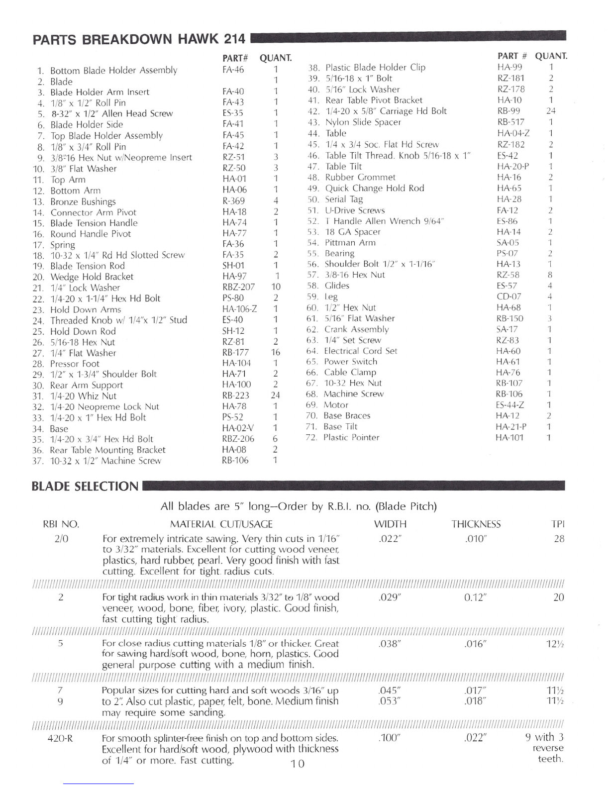
PARTS BREAKDOWN HAWK 214
PART QUANT. PART
#QUANT.
1. Bottom Blade Holder Assembly FA-46 138. Plastic Blade Holder Clip HA99 1
2. Blade 139. 5/16-18 x 1" Bolt RZ-181 2
3. Blade Holder Arm Insert FA-40 140. 5/16" Lock Washer RZ-178 2
4. 1/8" x 1/2" Roll Pin FA43 141. Rear Table Pivot Bracket HAlO 1
5. 8-32" x 1/2" Allen Head Screw ES-35 142. 1/4-20 x 5/8" Carriage Hd Bolt RB-99 24
6. Blade Holder Side FA-4l 143. Nylon Slide Spacer RB-517 1
7. Top Blade Holder Assembly FA-45 1 44. Table HA04-Z
1
8. 1/8" x 3/4" Roll Pin FA-42 145. 1/4 x 3/4 Sac. Flat Hd Screw RZ-182 2
9. 3/8"16 Hex ut w/ leoprerne Insert RZ-51 346. Table Tilt Thread. Knob 5/16-18 x 1" ES-42 1
10. 3/8" Flat Washer RZ-50 3 47. Table Tilt HA-20-P 1
11. Top Arm HA01 1-i8. Rubber Crornmet HA16 2
12. Bottom Arm HA-06 1 49. Quick Change Hold Rod HA-65 1
13. Bronze Bushings R-369 4-0. Serial Tag HA-28 1
14. Connector Arm Pivot HA-18 2 51. U-Drive Screws FA-12 2
15. Blade Tension Handle HA74 1 52.
r
Handle Allen Wrench 9/64" ES-86 1
16. Round Handle Pivot HA77 153. '18 CA Spacer HA-'14
2
17. Spring FA-36 154. Pittman Arm SA-05 1
18. 10-32 x 1/4" Rd Hd Slotted Screw FA35 255. Bearing PS-07 2
19. Blade Tension Rod SH-Ol 156. Shoulder Bolt 1/2" x 1-1/16" HA13 1
20. Wedge Hold Bracket HA-97 1 57. 3/8-16 Hex Nut RZ-58 8
21. 1/4" Lock Washer RBZ-207 10 58. Clides ES-57 4
22. 1/4-20 x 1-1/4" Hex Hd Bolt PS-80 259. Leg CD-07 4
23. Hold Down Arms HA-l06-Z 1 60. 1/2" Hex Nut HA68 1
24. Threaded Knob w/ 1/4"x 1/2" Stud ES-40 1 61. 5/16" Flat Washer RB-150 3
25. Hold Down Rod SH-12 1 62. Crank Assembly SA-17 1
26. 5/16-18 Hex ut RZ-81 2 63. 1/4" Set Screw RZ-83 1
27. 1/4" Flat Washer RB-l77 16 64. Electrical Cord Set HA60 1
28. Pressor Foot HA-l04 'I 65. Power Switch HA61 'I
29. 1/2" x 1-3/4" Shoulder Bolt HA7l 2 66. Cable Clamp HA76 1
30. Rear Arm Support HA-100 2 67. 10-32 Hex Nut RB-l07 'I
31. 1/4-20 Whiz Nut RB-223 24 68. Machine Screw RB-106 1
32. 1/4-20 Neopreme Lock Nut HA-78 169. Motor ES-44-Z 1
33. 1/4-20 x 1" Hex Hd Bolt PS-52 1 70. Base Braces HA-12 2
34. Base HA02-V 171. Base Tilt HA21-P 1
35. 1/4-20 x 3/4" Hex Hd Bolt RBZ-206 672. Plastic Pointer HA10l 1
36. Rear Table Mounting Bracket HA08 2
37. 10-32 x 1/2" Machine Screw RB-l06 1
BLADE SElECTION
All blades are 5" long-Order by R.B.I. no. (Blade Pitch)
MATERIAL CUT/USAGE WIDTH
For extremely intricate sawing. Very thin cuts in 1/16" .022"
to 3/32" materials. Excellent for cutting wood veneer,
plastics, hard rubber, pearl. Very good finish with fast
cutting. Excellent for tight radius cuts.
///
/
/
////
///
//
/
/
/
/
/
///
/
///
/
/
////
/
///
/
/
///
///
/
///
/
//
/
/
///
//
/
/
//
//
/
//
/
///
/
/
//
//
//
/
//
//
//
/
/
//
//
//
/
//
////
///
/
/
/
//
/
///
/
/////
/
//
//
//
//
/
/
/
//
//
/
///
//
/
//
/////
/
/
/
//
//
//
////
//
//
/
//
/
/
/
//
/
/
/
/
/
//
//
/
/
/
/
/
/
/
2 For tight radius work in thin materials 3/32" te 1/8" wood .029" 0.12" 20
veneer, wood, bone, fiber, ivory, plastic. Good finish,
fast cutting tight radius.
//////////////////////////////////////////////////////////////////////////////////////////////////////////////////////////////////////////////////////////////////////////////////////////////
5 For close radius cutting materials 1/8" or thicker. Creat .038" .016"
12Y2
for sawing hard/soft wood, bone, horn, plastics. Good
general purpose cutting with a medium finish.
//////////// /// ///I// //// //////////////////////////////////////////////// // /////// //////////////////////////////////////////////////// /////// ///IIIIIIII/IIIIIIIIIIIIIIIIIIIIIIIIIIII/II/III//
7 Popular sizes for cutting hard and soft woods 3/16" up .045" .017"
11}'2
9 to 2': Also cut plastic, paper, felt, bone. Medium finish .053" .018"
llY,
may require some sanding.
1111///1111/////11/11/111111111111/1111/111111/111111111111111111111111111111/111111111111111111111111/111111//1111/1111111111111111111/11111111111111/111111111111111111111111111111111111111
420-R For smooth splinter-free finish on top and bottom sides. .100"
.022" 9
with
3
Excellent for hard/soft wood, plywood with thickness reverse
of
1/4
or more. Fast cutting. 1
0
teeth.
RBI NO.
2/0
THICKNESS
.010"
TPI
28


SPECIFICATIONS HAWK 214 _
Length:
Width:
Height:
Weight:
Throat Depth:
Cutting Depth:
Length of Stroke:
Cutting Strokes
per minute:
26"
18"
44"
57 Ibs.
14"
2" hard and soft woods
13/16"
1,725
Motor Size:
Drive:
Work Table:
1/8 HP TEFC
Direct
10-1/2" round, polished aluminum. Tilts
45°Left or Right.
Sleeve
Optional
Bearing Type:
Dust Blower:
ACCESSORIES _
LIGHT
2LK
2MK
2RBK
STANDARD LIGHT
Heavy duty flexible arm, 16' long which usesa maxi-
mum 60 watt incandescent bulb with metal globe.
Allows light to be put close to the work and main-
tain this position. Comes complete with everything
to mount to your saw.
MAGNIFIERLIGHT
Flexible arm light with built-in 2 to 1 magnification
lens and scale to measure through the lens. Comes
with bracket to attach to a work bench edge. Uses
60 watt incandescent bulb, maximum.
RUBBERBELLOWSKIT
Kit comes with Rubber Bellows, mounting brackets,
hose and hardware to install on your Hawk 214 Saw.
The Bellows usesthe action of the arm to pump air
to keep an area around the blade free of sawdust.
6LE LEGEXTENSIONKIT
Bottom mounted LegExtension which increasesthe
height of your saw up to sixinches,with 2' increment
adjustments.
HA-81 FOOT SWITCH
Switch enables user to turn saw on and off by foot,
leaving the handsfree. Plugsdirectly into switch cord
and requires no wiring.
HA-85 BLADEALIGNMENT FIXTURE
Fixturethat holds bottom blade holder and alignsthe
blade to the center screw. Ensuresproper blade in-
stallation into the bottom holder.
HA-87 BLADE HOLDER RACK
Rack mounts to base and holds up to six bottom
blade holders with blades installed. Savestime when
changing blades.
HOW AND WHERE TO ORDER
REPLACEMENT PARTS AND ACCESSORIES _
TO SPEEDDELIVERYAND REDUCEERROROF REPLACE-
MENT PARTS,ALWAYSINCLUDETHE FOLLOWING INFOR-
MATION:
1. Give the complete identification of the machine.
A. Machine Name _
B. Model Number _
C. Serial Number _
2. Give the identification of the part.
A. Part Number _
B. Part Name _
You Can Reach Us
C. If necessary, return the old part as a sample.
3. Give us an address to return the part to.
Ship to: _
Your Name (Please Print)
Address _
Street P.O.Box Rural Route
City _
State Zip _
Country _
4. Send your order to:
ByPhone 1-620-562-3557
By
Fax
1-620-562-3557
By
Table of contents