Imerge IMerge AX-Platform User manual

Imerge
AX Platform
Service Manual

2
ENGLISH
Important
Servicing of this product in accordance with this service manual
should never be undertaken in the absence of proper tools, test
equipment and the most recent revision to this service manual which
is clearly and thoroughly understood.
This static control precaution symbol appears throughout this manual.
When this symbol appears next to a procedure in this manual, static
control precautions MUST be observed. Use a static control worksta-
tion to help ensure that static charges are safely conducted to ground
and not through static sensitive devices.
CAUTION
Technical Competence
The procedures described in this service manual should be performed by trained and
authorised personnel only. Maintenance should only be undertaken by competent
individuals who have a general knowledge of and experience with devices of this
nature. No repairs should ever be undertaken or attempted by anyone not having such
qualifications. Genuine replacement parts manufactured, sold or specified by Imerge
must be used for all repairs. Read completely through each step in every procedure
before starting the procedure; any exceptions may result in a failure to properly and
safely complete the attempted procedure.
Note: A note provides additional information to clarify a point in the text.
Important:
An Important statement is similar to a note, but is used for greater emphasis.
CAUTION:
A CAUTION statement is used when the possibility of damage to the equipment
exists.
WARNING:
A WARNING statement is used when the possibility of injury to service personnel
exists.
The information contained in this service manual pertains only to the AX platform
manufactured by Imerge as of the effective date of this manual or the latest revision
thereof. This service manual was prepared for exclusive use by appointed service
personnel in light of their training and experience as well as the availability to them of
parts, proper tools and test equipment. Consequently, we provide this service manual
for general information only without warranty of the results with respect to any applica-
tion of such information. Furthermore, because of the wide variety of circumstances
under which maintenance and repair activities may be performed and the unique nature
of each individual’s own experience, capacity, and qualifications, the fact that a cus-
tomer has received such information from us this does not imply in anyway that we
deem said individual to be qualified to perform any such maintenance or repair service.
Moreover, it should not be assumed that every acceptable test and safety procedure or
method, precaution, tool, equipment or device is referred to within, or that abnormal or
unusual circumstances, may not warrant or suggest different or additional procedures or
requirements.
This manual is subject to periodic review, update and revision. Customers are cautioned
to obtain and consult the latest revision before undertaking any service of the equip-
ment.

3
ENGLISH
Warnings
Disconnect the mains power to the unit during disassembly/assembly procedures. Do not perform any
service or maintenance with the power applied unless specifically told to do so in the procedure.
Use extreme care while performing service procedures with the cover removed or while working on the
unit with power connected. An electrical shock hazard does exist, and the power supply heatsinks can
deliver an electrical shock even when mains power is removed from the unit; be certain to observe all
standard safety precautions.
Special Tools and Equipment
The following tools (or their functional equivalents) are required to complete the recommended
service procedures.
Required Tools
No.1 Pozidriv Screwdriver (M3)
No.2 Pozidriv Screwdriver (M4)
Nutspinner M3 (5mm)
Flat nose Pliers
Anti-Static Workstation
Flat Nose Pliers
Pick Up Tool
Digital Multimeter
High grab adhesive (Please read the label for instructions of use)
Online Support
Use the World Wide Web (WWW) to view the latest version of this service manual, check for updates or
download files. The support area on our web site is password protected, please contact Imerge Support
for details.
Service manual address:
http://www.xiva.co.uk/support/servicemanual.html
The XiVA OEM Support Pages:
http://www.xiva.com/support
The XiVA Home Page:
http://www.xiva.com

4
ENGLISH
Table of Contents
Table of Contents
IMPORTANT ...................................................................................................................2
TECHNICAL COMPETENCE............................................................................................................. 2
WARNINGS ....................................................................................................................................... 3
SPECIAL TOOLS AND EQUIPMENT ................................................................................................ 3
ONLINE SUPPORT............................................................................................................................ 3
PAGE REFERENCES ........................................................................................................................ 5
CLEANING THE UNIT ....................................................................................................................... 6
TO CLEAN THE AUDIO CONNECTORS........................................................................................... 6
PACKAGING MATERIALS ................................................................................................................. 6
CLEANING & PACKAGING ...........................................................................................6
HANDLING ELECTROSTATIC DISCHARGE-SENSITIVE DEVICES ................................................ 7
DISASSEMBLY & ASSEMBLY.......................................................................................7
MOTHERBOARD (AX)....................................................................................................................... 8
REMOVING THE LID ....................................................................................................................... 10
FITTING THE LID ............................................................................................................................ 10
REMOVING THE CDROM DRAWER FRONT (METAL VERSION) ................................................. 12
FITTING THE CDROM DRAWER FRONT (METAL VERSION) ...................................................... 13
REMOVING THE CDROM DRAWER FRONT (PLASTIC VERSION).............................................. 14
FITTING THE CDROM DRAWER FRONT (PLASTIC VERSION) ................................................... 15
REPLACING THE CDROM DRIVE .................................................................................................. 16
REMOVING THE HARD DISK BRACKET ....................................................................................... 19
FITTING THE HARD DISK BRACKET............................................................................................. 20
REMOVING A HARD DISK DRIVE (HDD) ....................................................................................... 21
FITTING A HARD DISK DRIVE (HDD)............................................................................................. 22
REPLACING THE FAN .................................................................................................................... 23
REPLACING THE FRONT PANEL DISPLAY BOARD (FPDB) ........................................................ 25
REPLACING THE POWER SUPPLY UNIT (PSU) ........................................................................... 27
REPLACING THE MAINS INLET FILTER ........................................................................................ 28
REPLACING THE MEMORY MODULE ........................................................................................... 29
REMOVING THE DAUGHTER EXPANSION BOARD (IF APPLICABLE) ........................................ 30
FITTING THE DAUGHTER EXPANSION BOARD (IF APPLICABLE).............................................. 31
REMOVING THE MODEM ............................................................................................................... 32
FITTING THE MODEM .................................................................................................................... 33
REPLACING THE BATTERY ...........................................................................................................34
REPLACING THE CONTROLLER PORT ........................................................................................ 35

5
ENGLISH
Page References
*DA_REMOVE_LID*
*DA_FITTING_LID*
*DA_REMOVE_CDROM_FRONT*
*DA_FITING_CDROM_FRONT*
*DA_REMOVE_CDROM_DRIVE*
*DA_FITTING_CDROM_DRIVE*
*DA_REMOVE_MODEM_BRACKET_BOARD*
*DA_FITTING_MODEM_BRACKET_BOARD*
*DA_REMOVE_MODEM*
*DA_FITTING_MODEM*
*DA_REMOVE_HARDDISK_BRACKET*
*DA_FITTING_HARDDISK_BRACKET*
*DA_MOTHERBOARD_LAYOUT*
REPLACING THE AX MOTHERBOARD.......................................................................................... 35
PARTS LIST .................................................................................................................39
IMPORTANT .................................................................................................................................... 40
TESTING.......................................................................................................................41
INTRODUCTION.............................................................................................................................. 44
ESSENTIAL PREPARATION............................................................................................................ 44
TROUBLESHOOTING..................................................................................................44
QUESTIONS AND ANSWERS ........................................................................................................ 45
POWER CHECK .............................................................................................................................. 51
MOTHERBOARD CHECK ...............................................................................................................52
EXPANSION BOARD CHECK (IF APPLICABLE) ............................................................................ 54
MODEM PROBLEMS....................................................................................................................... 54

6
ENGLISH
Cleaning the unit
Regular dusting with a dry soft, non-abrasive cloth will generally keep the finish of the front panel and
chassis cover looking like new. Avoid the use of domestic cleaning products.
Dust or finger marks can be removed from the front panel using a soft, slightly damp cloth. Disconnect the
power cord before cleaning the unit. Ensure that no water is allowed to enter the case and do not reconnect
the power cord until you are certain that the unit is completely dry.
At no time should you allow any liquid to enter the unit; it may run into the electronic circuitry and cause
damage that will not be covered under the product warranty.
Note: Do not use abrasive cleaners on any part of the unit.
To clean the audio connectors
The audio sockets on the back of the unit are gold-plated and need no cleaning if gold-plated Phono plugs
are used. Otherwise, it is recommended that the end-user unplugs and reconnects the plugs at least once a
year.
Packaging Materials
We recommend that you retain all of the packing material and shipping boxes for the unit. They are custom
designed to reduce the likelihood of damage during shipping. We will accept no responsibility for any
damage occurring to the unit, or accessory, that is shipped in packing material other than the original
packing material.
Cleaning & Packaging

7
ENGLISH
Handling electrostatic discharge-sensitive devices
Any assembly or component part containing transistors or integrated circuits (ICs) should be considered
sensitive to electrostatic discharge (ESD). ESD damage can occur when there is a difference in charge
between objects.
Protect against ESD damage by equalising the charge so that the machine, the part, the work mat, and the
person handling the part are all at the same charge.
WHEN HANDLING ESD-SENSITIVE PARTS:
• Keep the parts in protective packages until they are inserted into the product.
• Avoid contact with other people.
• Wear a grounded wrist strap against your skin to eliminate static on your body.
• Prevent the part from touching your clothing. Most clothing is insulative and retains a charge even
when you are wearing a wrist strap.
• Use a grounded work mat to provide a static-free work surface.
Disassembly & Assembly

8
ENGLISH
Motherboard (AX)

9
ENGLISH
Whilst working inside the DH9300 we recommend that the PSU is covered with (?) to prevent contact with
the Power Supply Unit (PSU) which can cause an electric shock.
10
ENGLISH
Removing the Lid
TOOLS:
Pozi-driv No.1 screwdriver
PARTS USED:
MW00113-01 Cover (Black) MW00036-01 6x M3 (6mm) Black Screws
MW00105-01 4x Copper M3 (6mm) screws
PROCEDURE:
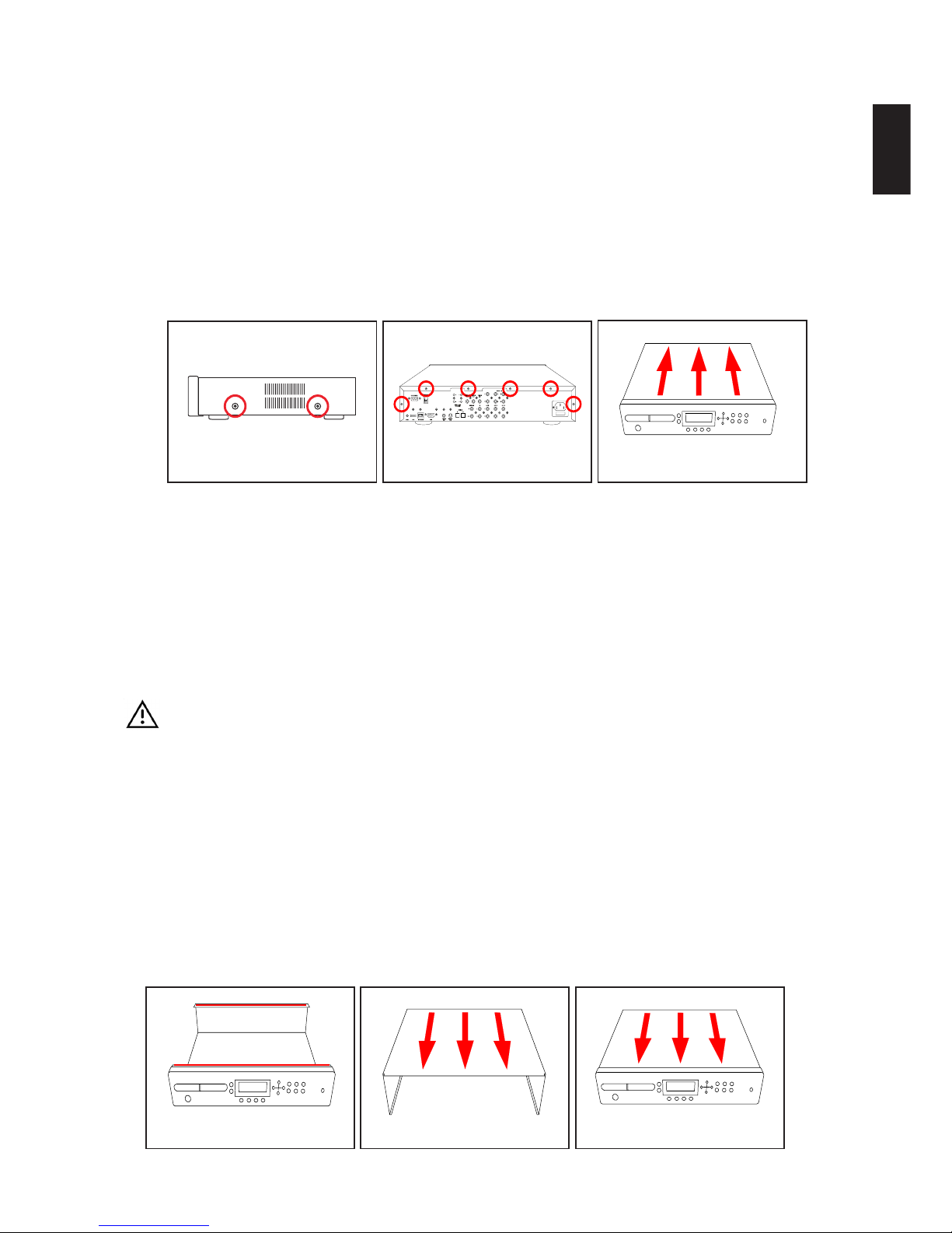
1. Remove the 4x M3 (Copper) screws from the left and right side of the unit. See figure 1.
2. Remove the 6x M3 (Black) screws from the rear of the unit. See figure 2.
3. Gently slide the lid towards the rear then lift up to remove, store in a safe place to prevent
damage. See figure 3.
Fitting the Lid
CAUTION:
EMC stripes are used along the top front and back edges of the chassis which can make the lid
difficult to fit. Do not try to force the screws into the holes as this can cause either damage to the
chassis or the screws thread which may prevent you from removing the lid again. Apply a little
downward pressure on the lid at the rear to help line up the holes.
TOOLS:
Pozi-driv No.1 screwdriver
PARTS USED:
MW00113-01 Cover (Black) MW00036-01 6x M3 (6mm) Black Screws
MW00105-01 4x Copper M3 (6mm) screws (if applicable)
PROCEDURE:
figure 1 figure 2 figure 3
figure 1 figure 2 figure 3

11
ENGLISH
1. EMC stripes are used along the top front and back edges of the chassis. See Caution and
Figure 1.
2. The lip on the lid fits neatly under the top of the front panel (See figure 2). Insert the lids’ lip into
the top of the front panel at a 35oangle and slowly sit the lid down at the rear (See figure 3).
3. You may have to apply a little downward pressure on the lid at the rear to align up the screw
holes.
4. Secure and tighten 6x M3 (Black) screws on the rear of the unit. See figure 4.
5. Secure and tighten 4x M3 (Bronze) screws on the left and right side of the unit. See figure 5.
figure 4 figure 5

12
ENGLISH
Removing the CDROM Drawer Front (Metal version)
CAUTION:
The CDROM drawer is likely to break if excessive force is applied during this procedure.
TOOLS:
Small flat bladed screwdriver Pin or Straighten out Paper clip (if necessary)
PARTS USED:
PL00010-01 CD Drawer Front
<P/NBR> 3M Double sided sticky pads
PROCEDURE:
This procedure covers the removal of the painted metal CDROM drawer front that is clipped to the
tray. See ‘Removing the CDROM Drawer Front (Plastic version)’ for the removal of the plastic
variant.
1. With the lid on and while the unit is powered, press the eject button to open the CD tray (See
figure 1).
In the unlikely event that you are unable to eject the CD tray, you can try the following methods.
Below the right hand corner of the CD drawer is a small manual eject pin hole, inserting a pin or
straightened out paper clip into this hole should open the drawer whilst the power is applied. If
this fails then you will need to remove the CDROM drive (See page
*DA_REMOVE_CDROM_DRIVE*) to gain access to the CD drawer front.
2. With the drawer still open (see figure 2), place the unit into standby and then remove the power.
3. The drawer front is attached to the drive’s plastic drawer front using 2x 3M double sided sticky
pads.
4. Using the flat bladed screwdriver, gently prise the metal drawer front from the CDROM’s
original drawer front. See figure 3.
5. After the metal drawer front has been removed, completely remove any traces for the double
sided sticky pads as new pads will need to be used to fit it again.
figure 1 figure 2 figure 3

13
ENGLISH
Fitting the CDROM Drawer Front (Metal version)
CAUTION:
The CDROM drawer is likely to break if excessive force is applied during this procedure.
TOOLS:
Pin or Straighten out Paper clip (For manual eject if necessary)
PARTS USED:
PL00010-01 CD Drawer Front
PROCEDURE:
This procedure covers the fitting of the painted metal CDROM drawer front that is clipped to the
tray. See ‘Removing the CDROM Drawer Front (Plastic version)’ for the removal of the plastic
variant.
1. With the lid on and while the unit is powered, press the eject button to open the CD tray (See
figure 1).
In the unlikely event that you are unable to eject the CD tray, you can try the following methods.
Below the right hand corner of the CD drawer is a small manual eject pin hole, inserting a pin or
straightened out paper clip into this hole should open the drawer whilst the power is applied. If
this fails then you will need to remove the CDROM drive (See page
*DA_REMOVE_CDROM_DRIVE*) to gain access to the CD drawer front.
2. With the drawer still open (see figure 2), place the unit into standby and then remove the power.
3. The drawer front is fitted to the CDROM drive with 2x 3M double sided sticky pads on the rear
side of the metal drawer. If the drawer front has been used before then remove all traces of the
double sided sticky pads before proceeding.
4. Place one at each end at about 1cm from the edge.
5. Centrally align the metal drawer front with the CDROM drawer front and carefully apply pres-
sure so that the pads to stick.
figure 1 figure 2 figure 3
14
ENGLISH
Removing the CDROM Drawer Front (Plastic version)
CAUTION:
The CDROM drawer is likely to break if excessive force is applied during this procedure. The
drawer front must be removed before the drive can be taken out of the unit.
TOOLS:
Small flat bladed screwdriver Pin or Straighten out Paper clip (if necessary)
PARTS USED:
PL00010-01 CD Drawer Front
PROCEDURE:
This procedure covers the removal of the plastic CDROM drawer front that is clipped to the tray.
See ‘Removing the CDROM Drawer Front (Metal version)’ for the removal of the painted metal
variant.
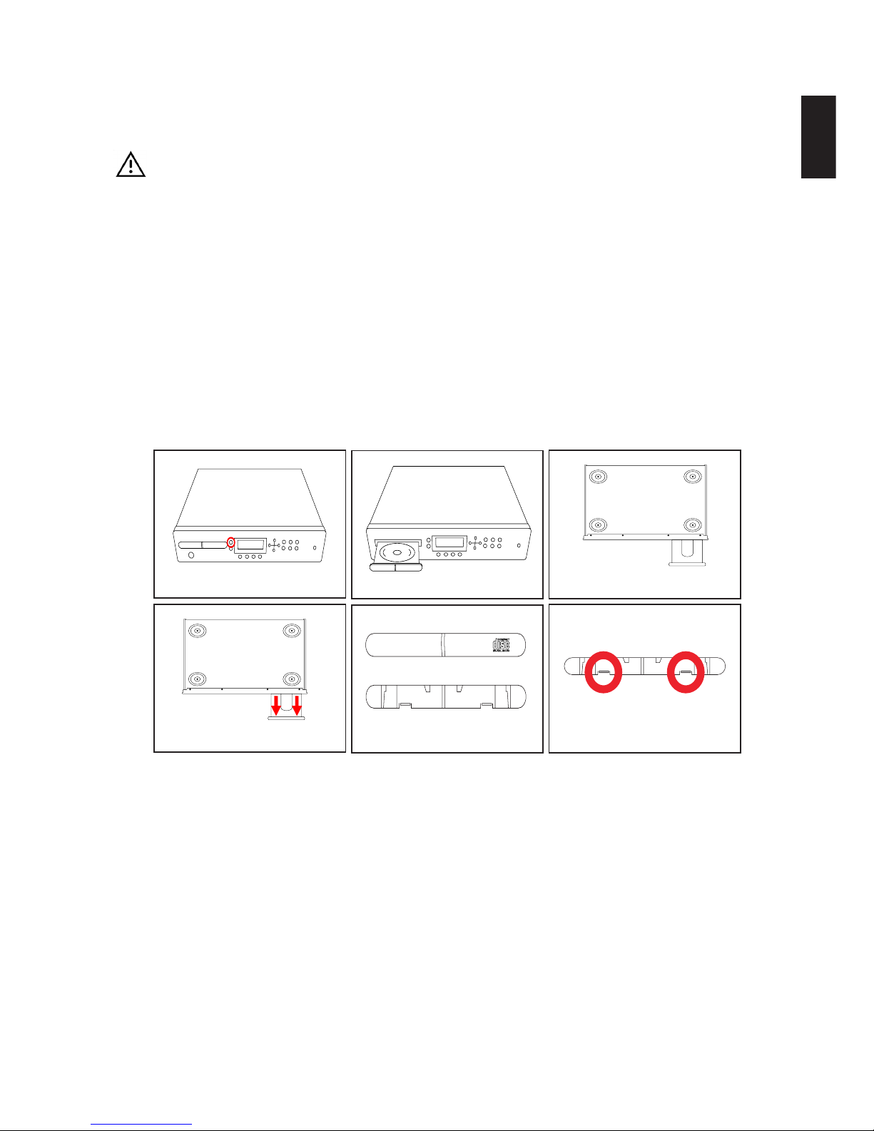
1. With the lid on and while the unit is powered, press the eject button to open the CD tray (See
figure 1).
In the unlikely event that you are unable to eject the CD tray, you can try the following methods.
Below the right hand corner of the CD drawer is a small manual eject pin hole, inserting a pin or
straightened out paper clip into this hole should open the drawer whilst the power is applied. If
this fails then you will need to remove the Front Panel (See page
*DA_REMOVE_FRONTPANEL*) to gain access to the CD drawer front.
2. With the drawer still open (see figure 2), place the unit into standby and then remove the power.
3. Turn the unit upside down for easier access (see figure 3).
4. On the underside of the CD drawer front you will see two clips (see figure 4).
5. Figure 5 shows the front (top) and back (bottom) of the drawer front.
6. Gently prise off the drawer front by carefully releasing the two clips (see figure 6) on the under-
side with a small flat bladed screwdriver.
7. Turn the unit upright.
8. Applying power to the CDROM drive will automatically close the drawer (if required).
figure 1 figure 2 figure 3
figure 4 figure 5 figure 6
15
ENGLISH
Fitting the CDROM Drawer Front (Plastic version)
CAUTION:
The CDROM drawer is likely to break if excessive force is applied during this procedure.
TOOLS:
Pin or Straighten out Paper clip (For manual eject if necessary)
PARTS USED:
PL00010-01 CD Drawer Front
PROCEDURE:
This procedure covers the fitting of the plastic CDROM drawer front that is clipped to the tray. See
‘Removing the CDROM Drawer Front (Metal version)’ for the removal of the painted metal variant.
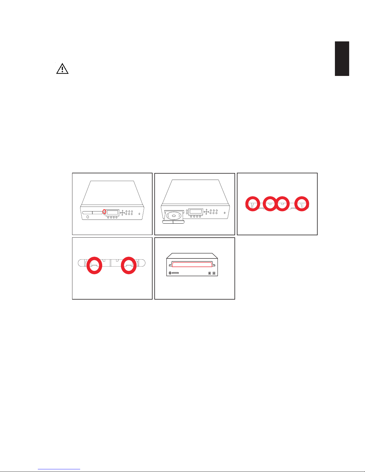
1. While the unit is powered on, press the eject button to open the CD tray. See figure 1
In the unlikely event that you are unable to eject the CD tray, you can try the following methods.
Below the right hand corner of the CD drawer is a small manual eject pin hole, inserting a pin or
straightened out paper clip into this hole should open the drawer whilst the power is applied. If
this fails then you will need to remove the Front Panel (See page
*DA_REMOVE_FRONTPANEL*) to gain access to the CD drawer front.
2. With the drawer still open, place the unit into standby and then remove the power.
3. On the top of the drawer front are two prongs (see figure 3) and two clips at the bottom (see
figure 4).
4. There is a ridge at the front of the drawer where the part is fitted (see figure 5). Clip the drawer
front on the top first then gently lift the prongs over the bottom ridge of CD drawer.
5. Applying power to the unit will automatically close the CD drawer.
figure 1 figure 2 figure 3
figure 4 figure 5
16
ENGLISH
Replacing the CDROM drive
WARNING:
There is a risk of electrical shock, the power supply can deliver an electrical shock even when the
mains power is removed from the unit; be certain to observe all standard safety precautions.
CAUTION:
The motherboard front panel display socket carries additional power, do not under any circum-
stances attempt to connect a cable plugged in this socket into the hard disk drives or CDROM drive.
This will short circuit the attached device and/or motherboard rendering it inoperable.
TOOLS:
Pozi-driv No.1screwdriver Small flat bladed screwdriver
High Grab Adhesive PSU (Power Supply Unit) or another unit
PARTS USED:
MW00036-01 4x M3 (6mm) Black MW00038-01 4x M3 (6mm) Black
IC00097-01 CD-ROM ASUS CD-S520 MW00114-01 CD Support Bracket
MW00043-01 4x M3 Shakeproof Washers (Black)
PROCEDURE:
Disassembly
1. Remove the Lid. (See page *DA_REMOVE_LID*)
2. Remove the CDROM drawer front (See page *DA_REMOVE_CDROM_FRONT*)
3. Carefully peel off the EMC tape from the CDROM which is fixed between the drive and chassis
front panel, try not to damage the tape as it can be reapplied again.
4. Using a Pozi-driv No.1 screwdriver, remove 2x M3 screws from each bracket that mount the
drive and brackets to the chassis. You may need to move the front panel and hard disks cables
aside for easier access.
5. Lift the drive up slightly at the rear to release the power cable from the cable retaining bunny
clip. Carefully remove the IDE ribbon (black connectors), Power and Audio cables from the rear
figure 1 figure 2 figure 3
figure 4 figure 5 figure 6

17
ENGLISH
of the drive. Be careful not to touch the power supply unit as it may still hold charge or break
any of the attached cables.
6. Gently lift the CDROM along with the bracket out of the unit.
7. Remove 4x M3 screws securing the CDROM drive to the bracket.
8. The CDROM is glued to the mounting brackets with a high grab adhesive to prevent it from
slipping forwards or backwards whilst in transit. The brackets can be removed by carefully
prising them away from the drive using a thin flat bladed screwdriver.
Preparing a new CDROM drive
1. Brand new CDROM drives are supplied with their facia fitted, in order to use the drive this must
be removed first.
2. To remove the CDROM facia you must open the CDROM’s drawer to take off the drawer front.
This can be achieved by applying power to the unit and by pressing the eject button (See figure
1). The power can be supplied by either temporarily connecting the drive to the unit and turning
the unit on or by connecting the drive to an external PSU (Power Supply Unit). Make sure that
the power is disconnect after the drawer is opened and before proceeding to the next step.
3. The original CDRom drawer front is clipped on to the drawer in much the same way as it’s
replacement (See page *DA_REMOVE_CDROM_FRONT*) if using the plastic version. It can
be easily removed without the use any tools, simply lift the bottom of drawer front to release the
clips and gently slide it up, Please note: The CDROM drawer is likely to break if excessive force
is applied during this procedure.
4. Figure 3 shows the location of plastic tabs that fix the facia to the drive. You will need a flat-
bladed screwdriver to carefully prise the facia off
5. If the unit is going to be fitted with a metal CD drawer front then fit the original drawer front back
on again.
figure 1 figure 2 figure 3
18
ENGLISH
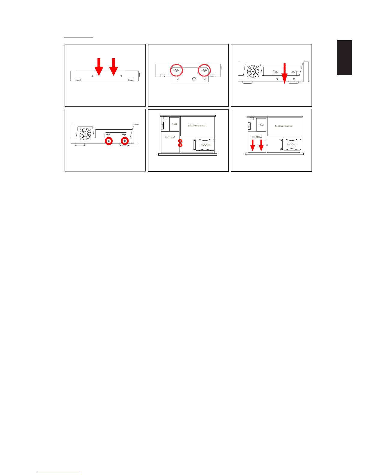
Assembly
1. Ensure that the CDROM’s facia has been removed, if not then carefully prise off the facia with a
small flat bladed screwdriver (See ‘Preparing a new CDROM drive’ before this section).
2. Set the jumper on the rear of the drive to master, a diagram of the jumper settings can either be
found on a rear or top label.
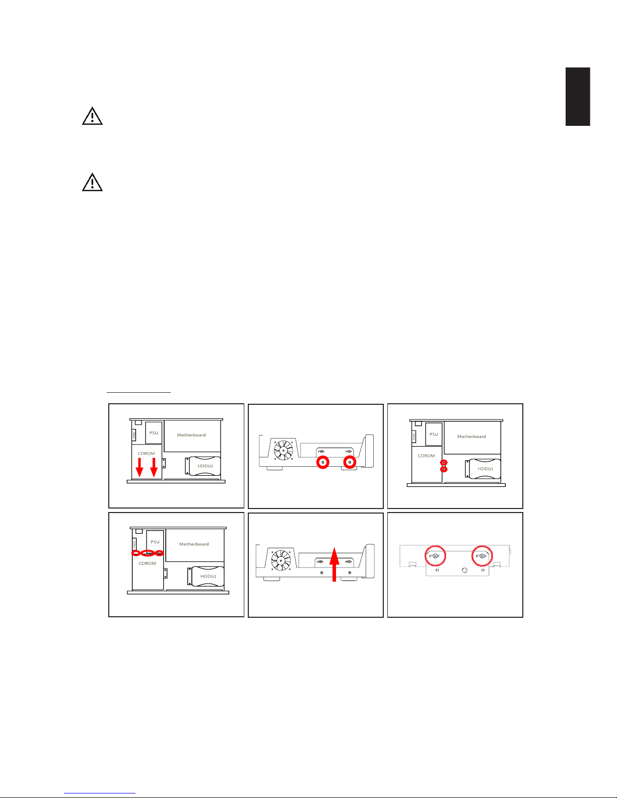
3. In order to make sure the CDROM drive does not move from it’s position in transit, put two
small beads (3mm in diameter) of high grab adhesive in between the drives mounting holes
(perform on each side). See figure 1.
4. The CDROM bracket is not symmetrical, the flat edge fits to the front left hand side of the
chassis and the angled part is secured to the two mounting pillars opposite within the chassis.
Mount each side of the CDROM drive to the bracket using 2x M3 screws. See figure 2.
5. Gently place the drive into the chassis making sure that the foam EMC gasket (between the
front panel and CDROM drive) does not obscure the CDROM’s play and eject buttons. Not
correctly positioning the drive can also result in the EMC gasket pushing the front of the drive
up, mis-aligning the CDRom drawer front. See figure 3.
6 Align the drive holes with those on the bracket, making sure its flush against the front panel
metalwork then insert and tighten the 4x M4 screws. See figures 3 & 4.
7. Clean any excess adhesive that may have smeared above the bracket with a damp cloth.
8. Connect the IDE cable from Secondary IDE socket (marked PL9) on the motherboard to the
CDROM drive. Do not plug the IDE cable in to the socket marked ‘Front Panel’ as this will
damage the drive. (See page *DA_MOTHERBOARD_LAYOUT* for motherboard layout)
9. Connect the Power cable and Audio lead to the drive and ensure the power cable is neatly
retained by the bunny clips.
10. Replace / Fix the EMC tape from the front panel to the top of the CDROM drive See figure 6.
11. Finally, fit the CDROM drawer front, if required (See page *DA_FITTING_CDROM_FRONT*)
figure 1 figure 2 figure 3
figure 4 figure 5 figure 6

19
ENGLISH
Removing the Hard Disk Bracket
CAUTION:
The motherboard front panel display socket carries additional power, do not under any circum-
stances attempt to connect a cable plugged in this socket into the hard disk drives or CDROM drive.
This will short circuit the attached device and/or motherboard rendering it inoperable.
TOOLS:
Pozi-driv No.2 screwdriver
PARTS USED::
<P/NBR> 2x M4 6mm MW00109-01 M4 Shakeproof Washers Zinc
<P/NBR> 2x M3 6mm MW00043-01 M3 Shakeproof Washers Black
PROCEDURE:
1. Remove Lid (See page *DA_REMOVE_LID*)
2. Remove the Power cables and IDE ribbon (black connectors) if connected from the hard
disk(s). See figures 2 and 3.
3. Locate and remove the two M4 screws beneath the hard disk cable end that fix the metal
bracket to the bottom of chassis. See figure 4.
4. On the front right side of the chassis you will find a second pair of M4 screws to remove. See
figures 5 and 6.
5. Carefully lift the hard disk and bracket assembly from the unit.
figure 4 figure 5 figure 6
figure 1 figure 2 figure 3

20
ENGLISH
Fitting the Hard Disk Bracket
CAUTION:
The motherboard front panel display socket carries additional power, do not under any circum-
stances attempt to connect a cable plugged in this socket into the hard disk drives or CDROM drive.
This will short circuit the attached device and/or motherboard rendering it inoperable.
TOOLS:
Pozi-driv No.2 screwdriver
PARTS USED::
<P/NBR> 2x M4 6mm
<P/NBR> 2x M3 6mm
PROCEDURE:
1. The hard disk drive bracket is fitted in the front right hand corner of the unit (figure 1), one side
is secured against the front right side of the chassis.
2. Position the bracket over the screw holes ensuring the up folded metal is flush against the front
right side (figures 2 & 3) of the unit.
3. Insert and tighten the two M4 screws beneath the hard disk cable end (figure 4) and then the
pair of M3 screws that secure the bracket to the front right side of the unit (figure 3).
4. Fit the IDE ribbon (black connectors) into the hard disk(s) (figure 6) and motherboard socket
marked PL8.
5. Fit the Power cable(s) to the hard disk(s) (figure 6) and motherboard socket marked PL12.
figure 4 figure 5 figure 6
figure 1 figure 2 figure 3
Table of contents


