1
Scheda tecnica STEKCDG2TP_IT
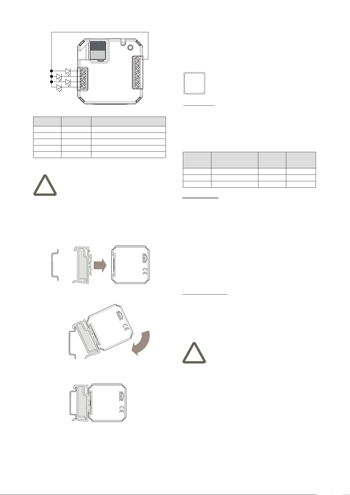
Warning! The outputs of the device are dedicated
exclusively to the connection of low-consumption
LEDs. Connecting other devices or using them as
generic outputs is not allowed.
!
Description
The ekinex®universal interface is a KNX S-mode device
that can be used as input or output. Depending on the
version, the device is provided with:
- inputs to connect to the bus devices with free-potential
contacts or NTC passive temperature sensors;
- output to control low-consumption LEDs.
The device is provided with an integrated bus commu-
nication module and is realized in a compact design for
installation in ush-mounting wall boxes. The device is
powered by the KNX bus line with a SELV voltage 30 Vdc
and does not require auxiliary power. The scanning volta-
ge for the input channels is produced by the device.
Versions
Code Inputs
Outputs
(low-con-
sumption
LEDs)
EK-CC2-TP 2 for potential-free contacts 2
EK-CD2-TP 4 for potential-free contacts 4
EK-CG2-TP
4 congurables Individually for
potential-free contacts or NTC
temperature sensors
4
Functionalities
Each input channel of the device can be programmed as
[DI] to carry out the function of:
• on/o switching of single loads or group of loads;
• detecting the state of signaling contacts (from safety
devices, alarms, etc.);
• recalling and saving of scenes;
• sending values on the bus (temperature, brightness,
etc.);
• switching to forced operating mode (lock);
• counting of impulses and switching cycles.
Main characteristics
• Housing in plastic material
• Wall installation in ush mounting box or, with a
mounting support, on 35 mm rail (according to EN
60715)
• Protection degree IP20 (installed device)
• Classication climatic 3K5 and mechanical 3M2 (ac-
cording to EN 50491-2)
• Pollution degree 2 (according to IEC 60664-1)
• Weight 20 g
• Dimensions 43 x 43 x 16 mm (WxHxD)
Technical data
• Power supply 30 Vdc from KNX bus line
• Current consumption < 10 mA
Environmental conditions
• Operating temperature: - 5 ... + 45°C
• Storage temperature: - 25 ... + 55°C
• Transport temperature: - 25 ... + 70°C
• Relative humidity: 95% not condensing
Accessories
Rail-mounting support
The device can be mounted on 35 mm rail (according to
EN 60715) with the support EK-SMG-35 to be ordered
separately.
EK-SMG-35
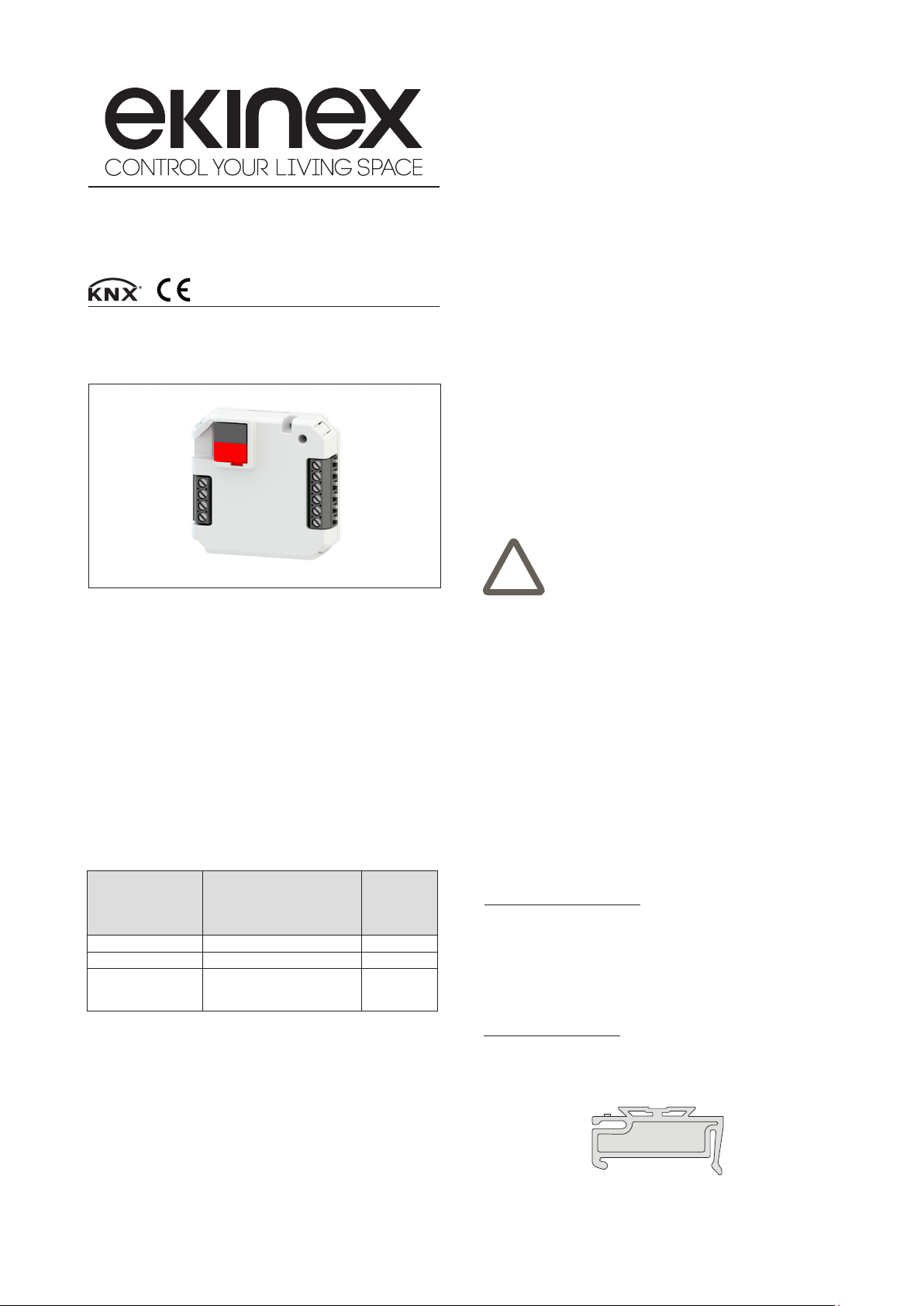
Universal interface
Codici: EK-CC2-TP (2 IN, 2 OUT)
EK-CD2-TP (4 IN, 4 OUT )
EK-CG2-TP (4 IN congurables, 4 OUT)
KNX bus device for connecting conventional (not KNX) switches,
sensors or NTC temperature sensors (to the inputs) and/or low-
consumption LEDs (to the outputs). It has to be used in KNX
installations for control of homes and buildings.
A couple of input channels can be programmed to carry
out the function of:
• dimming of lighting devices;
• controlling drives for shading devices (such as shut-
ters, blinds, curtains, etc.).
Each output channel of the device can be programmed
as [DO] for:
• controlling low-consumption LEDs to be used as sta-
tus feedback, orientation nightlights, etc.
As an alternative to programming it as [DI], each input
channel of the EK-CG2-TP version can be programmed
as [AI] for:
• measuring of the air mass temperature with a NTC pas-
sive temperature sensor (NTC 10 kΩ at 25 °C) to be
connected to the input with possibility of sending the
value on the bus
• 2 points (ON / OFF) or proportional (PWM or con-
tinuous) room temperature regulation. The device
is provided with 2 conduction modes (heating and
cooling) with switching via bus and 4 operating modes
(comfort, standby, economy and building protection)
with separate setpoints for heating and cooling.
Automatic switching function of the operating mode
depending on presence or opening windows. The re-
gulation may work with a weighted average of the two
temperature values
REAEKCDG2TP