IMET Spa BS300/60 AFI-E User manual

TRADUCTION OF THE ORIGINAL INSTRUCTIONS FOR USE
BS 300/60 AFI-E ED.2010 rev.00
1/61
IMET Spa
Loc. Tre Fontane - Cisano Bergamasco
Tel. 035/4387911 - Fax. 035/787066
Web site: www.imetsaws.com
E-mail: imet@imetsaws.com
Automatic, hydraulic bandsaw BS300/60 AFI-E
USER’S INSTRUCTIONS

TRADUCTION OF THE ORIGINAL INSTRUCTIONS FOR USE
BS 300/60 AFI-E ED.2010 rev.00
1/61
1
We recommend to read carefully the information here included in order to install, use and maintain correctly
and safely this machine.
Please refer always to this instruction manual in case of assistance service need and keep it carefully for all
the machine life. The reference numbers in Italy are +39 035 4387918 and +39 035 4397828.
A consequence of the continuous improvement of the product is that some images/descriptions here included
could not correspond to the improved features of the machines.
Your kind collaboration would help us in intevening asap.
In the enclosed Compliance Declaration you will find the Safety and Reference Norms applied during the
planning and construction of this machine.
The choice and the use of the parts have been made by considering the conditions of use and the long
machine life.
The identification plate, with the serial number, is fixed on the front right angle of the base or on a side of
control box.
1.1 - ATTACHED DOCUMENT FOR E.M.C. ( INDUSTRIAL ENVIRONMENT)
The user is responsible for installation and use of this machine in compliancewith the
manifacturer's instructions shown in this manual. This plant meets the protection requirements in
accordance with the Directives 2006/42/EEC and 2004/108/EEC,
as for electromagnetic compatibility (EMC).
In particular, it follow the technical instructions of the Rules EN55011,EN50082-2 and it has been
realized for industrial and not for household use.
In the event that should be electromagnetic interferences the user is responsible for solving the
problem together with the technical assistance of the manifacturer.
Before installing the machine the user must take into account possible electromagnetic problems
of the working area. In particular, we suggest installing the plant away from:
-signalling, control and telephone cables; -radiotelevision transmitters and receivers;
-computers or controlling and measuring instrument; -safety and protection devices.
The electric supply cable must be kept as short as possible, well right and without wires.
The covers, the door and the frame must be suitably closed when the plant is operating.
Under no circumstances the plant must be modified except for adjusting and changing established
by the manifacturer.
Follow the maintenance schedule.
TRADUCTION OF THE ORIGINAL INSTRUCTIONS FOR USE
BS 300/60 AFI-E ED.2010 rev.00
2/61
===========================================================================
CE DECLARATION OF CONFORMITY (encl. II A DIR 2006/42/CE) / 01
===========================================================================
THE MANUFACTURER : IMET S.p.A
Località Tre Fontane
24034 - CISANO BERGAMASCO –BG- ITALIA
HEREBY DECLARES THAT
in designing and manufacturing the machine described here below , we have considered the most important
requirements of safety and health dictated by the European Directives of the Machine Security. Remember
that this declaration loses its validity if machine is modified without our agreement.
Trade name BAND SAWING MACHINE FOR METALS
Code / Model / Type
Manufacturing year
Serial number
IT IS IN COMPLIANCE WITH THE DIRECTIVES
DIRECTIVE 2006/42/CE OF THE EUROPEAN PARLIAMENT AND OF THE COUNCIL OF THE
17TH/05/2006 REGARDING THE MACHINES AND THAT MODIFIES THE DIRECTIVE 95/16/CE;
DIRECTIVE 2004/108/CE OF THE EUROPEAN PARLIAMENT AND OF THE COUNCIL OF THE
15/12/04 REGARDING THE ELECTROMAGNETIC COMPATIBILITY -EMC-
DIRECTIVE 2006/95/CE OF THE EUROPEAN PARLIAMENT AND OF THE COUNCIL OF THE
12/12/06 REGARDING ELECTRICAL EQUIPMENT FOR USE OF LOW VOLTAGE -LVD-
HARMONIZED STANDARDS REFERENCE EN.12100-01; EN 55011, EN50082-2, EN 13898, EN
60204 LEGISLATIVE DECREE N.17 OF THE 27TH OF JANUARY 2010.
AND AUTHORIZING THE PERSON LISTED BELOW TO ISSUE THE TECHNICAL FILE.
Date : 01.01.2010
The signatory identification The manager
Angelo Meroni
--------------------------------------------------------------------------------------------------------------------------
File : Machine no. Delivery note no Dated
…………………….
………………..
………………..

TRADUCTION OF THE ORIGINAL INSTRUCTIONS FOR USE
BS 300/60 AFI-E ED.2010 rev.00
3/61
---------------------------------------------------------------------------------------------------------------------------

TRADUCTION OF THE ORIGINAL INSTRUCTIONS FOR USE
BS 300/60 AFI-E ED.2010 rev.00
4/61
3 - MACHINE NOISE
The decibel pointed out in the workplace in the conditions under described is appointed to the simoultaneous
working of some machine parts in motion ( it depends on the detailed cycle ) added to that one of the tool
when is cutting the workpiece.
In several moments the decibel are pointed out to note the different using conditions.
The phon-meter is placed at about 1 meter near the machine and at about 1,60 m from the floor.
The results of each test is in dBA and they mean the average of 3 tests made from the: left side,
opposite side, right side.
For any machines the using conditions are the following :
When running at the highest blade speed without cutting: dBA 63
When cutting a steel solid (St12=~C20 diameter 100mm) at a suited blade speed: dBA 75
( the measuring is = + - 2dB ).
In the standard production the test is made by a same machine of above mentioned one, in compliance with
E.C. safety norms 2006/42/CE . Usefull is the reference Guide 2003/10/EEC.
The use of the machine in bad conditions or the use of the wrong tools cause also sensitive alterations of
these tests and it is prejudicial for the health of the staff and for the good results of the work .
Most of all the noice depends on the cutting material, on its sizes and on the locking system.
By expecting that above mentioned decibels could be exceeded, we recommend the operator the using of the
personal means of protection ( head phones, plugs etc. ) in case of working a long time at highest
levelspositioning/clamping in the vice, taking into account other possible machinery running nearby
and the characteristics of the working place
3.1 - ADDITIONAL HEALTH AND SAFETY REQUIREMENTS
This type of machine, manually controlled during some working operations, must respond to further health
and safety requirements as specified by article 2.2 of the Annexed I of the European Directive2006/42/EEC .
In particular, the level of vibrations emitted by the machine while in use must be clearly specified in the
instructions.
This machine does not emit vibrations of a level higher than 2,5 m/s 2
The measurement procedure used conforms to the general norms applied to this type of machine.
Usefull is the reference Guide 2002/44/EEC.
As in the preceding paragraph, using the machine in unsuitable conditions or using the wrong tools
can cause changes affecting this value, endangering the health of the work force as well as the
quality of production.
Vibrations emitted during cutting may be amplified by the material, by its dimensions and its
positioning/clamping in the vice.
TRADUCTION OF THE ORIGINAL INSTRUCTIONS FOR USE
BS 300/60 AFI-E ED.2010 rev.00
5/61
4 - GUARANTEE NORMS
I.ME.T. offers a wide range of sawing machines and accessories, destined to who buys/uses them as part of
a commercial or professional activity.
The manufacturer grants that this product has been strongly controlled and that there are no defects in the
used and working materials for a period of 12 months from the date of the delivery note.
The italian law D.L. n° 24 issued on 02/02/2002 and valid since 23/03/2002 (which carries out the European
Directive 1999/44/CE) indicates different terms only for convenience products for private use.
If the user points out some defects to the manufacturer during the warranty time, the manufacturer will
replace the components that are considered defected.
In case of reparation of the machine during the warranty time the shipment will be accepted only if the
delivery is Free Destiny (that is the freight costs are supported by the owner of the machine), and the return
of the machine to the customer is considered EX WORKS.
If the manufaturer is not able to remplace a component within an acceptable time, both companies
(manufacturer and user) will reach an agreement for satisfying completely the needs of the user.
The a.m. warranty is not valid in case of accidental damages, or defects provoked by a wrong use of the
machine or maintenance, by variations made on the machine, or by the use of the machine in a place not
corresponding to the indicated enviromental specifications.
4.1 - The manufacturer does not offer further warranties, written or spoken, explicit or implicit of its products
and does not offer implicit warranties on saleability or adequacy for particular uses not foreseen by the
agreement.
The a.m. limitations and exclusions can also be not applicable in Countries, where there are no implicit limits
of warranty time on the products. Anyway each implicit warranty is limited to a time of 12 months from the
date of the delivery note.
4.2 - The date of manufacture, deducible from the serial number placed on the machine, is a very necessary
reference for the warranty, for the assistance after-sale and for the identification of the product.
Each tampering on the products, expecially the installation of safety devices, will relieve the manufacturer of
any kind of responsability.
The parts most subject to rapid and continuous wear are not included in the warranty (for example:
transmission belts, gaskets, oils, blades, and so on).
For the electrical, electronic and hydraulic equipments and for the other equipments having its own
individuality (of which there is the possibility to know the name of the constructor), the manufacturer gives to
the user the same warranty received by the primary constructor of these parts.
4.3 - The components replaced during the assistance operated by the manufacturer have a warranty of 6
months from the installation date indicated on the Technical Service paper, one copy of which is given to the
owner.

TRADUCTION OF THE ORIGINAL INSTRUCTIONS FOR USE
BS 300/60 AFI-E ED.2010 rev.00
6/61
5 - SUMMARY pag.
1- PREMESSA 2
2 –CONFORMITY DECLARATION 3
3 –AIR NOISE 4
4 –GUARANTEE NORMS 5
5 –Index 6
6 –Technical characteristics 7
7 –Installation –minimum requirements 9
8 –Moving and transit 9
9 –Fittings/optionals 11
10 –Blade choice 12
11 –Foreseen use and controindications 14
12 –Machine description 17
13 –Work preparation 18
14 –Band tensioning 19
15 –Functioning 20
16 –Regulations 25
17 –Maintenance –for the user 27
18 –Band running-in 28
19 –Machine running-in 28
20 –Draining of used/produced substances 29
21 –Trouble-shooting 29
22 –Machine demolition 31
23 –Spare parts 32
24 –Maintenance –for qualified technicians 33
Electrical drawings
Hydraulic diagram
Spare Parts drawings
TRADUCTION OF THE ORIGINAL INSTRUCTIONS FOR USE
BS 300/60 AFI-E ED.2010 rev.00
7/61
6 –TECHNICAL DETAILS
Automatic electronic bandsaw with numeric control and hydraulic working , suitable for cutting metal profiles
and solids from 0 to 45 deg. left in automatic cycle, from 0 to 60 deg. left in semiautomatic cycle Material
feeder equipped with recirculating-ball screw. In compliance with E.C. - CSA - UL Safety Norms and with the
Norms of Electromagnetic Compatibility (EMC
STANDARD MODEL EQUIPPED WITH:
2 SPEED Three-phase motor, - with band speed 35/70 m/min. - electrical components complying with E.C.
Norm EN60204-1, EN55011, EN50082-2
- low voltage (24V), main switch with interlocking attachment and minimum tension coil, thermo-magnetic
overload motor protections, emergency stop
- easy to use CNC control; all operating functions of the machine are programmed from the control panel,
Showing of the operating conditions, band speed, piece counter and number of pieces still to cut on an
alphanumeric display, , - autodiagnostics circuit displaying error CODES wholly controlling the machine
actuators - front fixed screw vice with hydraulic action, jaws height 130 mm - quick and positive location at 0
feeder equipped with recirculating-ball screw, 300 mm maximum opening, 4 mm minimum stroke, 210 mm
minimum scrap-end,.- feeder vices fitted to a floating plate, sliding by ball-bushing on chromium-plated and
tempered guides- monobloc floor stand predisposed for handling with lift truck Connection for loading roller
tables - unloading chute -removable chip tray and tank, coolant pump and washing spray gun, hydraulic unit
with oil. New band-cleaning device by means of a brush, , - bi-metal band, wrenches and manual of
instructions, maintenance and spare parts.
WIDE RANGE OF ACCESSORIES: Two pressure reducers for hydraulic vices with gauges, upper rollers for
cutting more pieces side by side (max dimensions 300x100 mm, only for straight cut) , RTS = modular
loading roller tables, 400 mm wide and 2 m long.
If not differently indicated, all data reported in this manual refer to the standard version,
suitable for working at 400 V / 50 Hz THREEPHASE .
= cutting capacity ( max. dimensions on PROFILES & TUBES)
= BLADE DIMENSIONS = WEIGHT =VICE OPENING
= motor choice and blade speeds (at 50 Hz);
mm.
Kw
Mt/min
mm.
Kg.
mm.
mm.
mm.
2765 +-10
X27X0,9
1,5
3~
18 to
110
300
635
255
230
300x180
210
190
200X160
1,5/1,8
35/70
300
630
135
110
130X100
N.B. If the device of MINIMAL LUBRICATION is placed on the machine, the cutting capacity is reduced about
10 mm due to the spray nozzles on the anterior band guide.
Dimensions
(mm)
B
width
L
lenght
H
height
H min.
worktable
In use
1800
1850
1880
870
For transport
1800
1750
1600

TRADUCTION OF THE ORIGINAL INSTRUCTIONS FOR USE
BS 300/60 AFI-E ED.2010 rev.00
8/61
7 - INSTALLATION
The machine can work according to the parameters provided by the manufacturer if it is rightly installed and
the minimum requirements are observed, as follows :
- Machine must be used indoor and with temperatures from +5 to + 40 ° C.
- The relative humidity of the environment must not go over 95%.
- The nominal value of the voltage of electric energy must be between + - 10 and the frequency of the
nominal value must be between + - 2%.
The floor must have good characteristiques of capacity and level.
Floor space, operator position and working area are indicated in the included drawing that concerns the
machine only without fittings as optional.
Work table must be leveled: by using the screws and nuts (NOT SUPPLIED) put in the little feet holes fix the
machine to the floor .
The included electrical schemes reproduces the necessary details to arrange the connections, to be
predisposed for 5KW power request.
Grounding of all electric parts thanks to a GREEN/YELLOW wire, linked via a TN system to the power supply
cable. A supplementary grounding point –marked “PE” – can possibly be located on the metallic structure of
the machine.
7.1 - DIFFERENTIAL PROTECTION
For the connection of the differential protection on the power supply line it is necessary to use
switches with a threshold of interference on the power dissipation of not less than 300 mA (size 0.3
A or higher is recommended), having possibly time adjustment availability (0>1.5 sec).
E.M.C. Electromagnetic noise
This machine has been foreseen for industrial and not for household use. In the event that should be
electromagnetic interferences the user is responsable for solving the problem together with the technical
assistance of the manufacturer. Before installing the machine the user must take into account possible
electromagnetic problems of the working area. In particular we suggest to install the plant away from:
- signalling, control and telephone cables;
- radiotelevision transmitters and receivers;
- computers or controlling and measuring instruments;
- safety and protection devices.
8 –TRANSPORT & LIFTING
For the transport of the machine only the methods indicated below are possible. However, be sure that the
means of transport snd lifting are able to stand the machine's weight and its packing (about 1000 Kg):
WARNING
The personnel in charge of loading, unloading and moving the machines should use protective gloves.
WARNING
When lifting or moving the machine, or a part of it, take care of clearing the operations area of the people,
considering also an appropriate safety area around it, so as to avoid any risks of injuring people or damaging
things located nearly.
Special packings –wooden crate , wooden case –may be predisposed on request, by charge.
ALL THE OPERATIONS THAT INVOLVE MOVING THE MACHINE MUST BE CONDUCTED WHILE
RESPECTING THE FOLLOWING BASIC RULES:

TRADUCTION OF THE ORIGINAL INSTRUCTIONS FOR USE
BS 300/60 AFI-E ED.2010 rev.00
9/61
+ When moving the machine, an appropriate means has to be used, with a loading capacity higher than
the weight to lift, which is indicated on the machine.
+ When choosing and then using equipment such as ropes, chains or lifting belts, be careful about their
geometry during the lifting and about the consequent actual loading capacity.
+ The machine is structured so as to offer lifting points, which are appropriately indicated and will have to
be used for lifting it.
+ In case the lifting belts touch parts of the machine, nylon belts are required; ropes or chains wrapped
with jute or clean covering can also be used. A great care is necessary while slinging and moving the
machine in order to hinder damages.
+ All operations have to be conducted with graduality, so as to avoid jolts and dangerous situations.
+ The person in charge of the operations has to make sure that all the national, local and company norms
in reference to injury prevention and work safety are respected.
+ Onr or more areas for material storage have to be identified.
Transport with machine at sight
This type of transport is usually chosen for deliveries by covered truck, in case of short trips. The machine is
wrapped with thermoplastic material in order to assure a suited protection of all its parts; the machine is then
loaded on a truck and should be wrapped with ropes that tie it up . To lift it, use a forklift from front side of
machine, with forks length 1.5 m or more.
Warning: if machine is delivered by open trucks, please cover it !
Transport with wooden crate or wooden case. ( BY REQUEST , ON CHARGE )
The machine is wrapped with thermoplastic material in order to assure a suited protection of all its parts; then
it is packed into a wooden crate or cage to protect it from collisions, inclement weather and so on.
To lift it, use a forklift from front side of machine, with forks length 1.5 m or more (see picture ).
You need to follow the indications you find on the packing before proceeding to moving or opening it.
WARNING
The size of the packing varies according to the machine ordered and its configuration.
WARNING
The machine is fixed to the packing by means of screws, so as to hinder that it can move during the transport
(see drawing in the following page)

TRADUCTION OF THE ORIGINAL INSTRUCTIONS FOR USE
BS 300/60 AFI-E ED.2010 rev.00
10/61
FITTINGS ASSEMBLING
The installation informations are supplied together to the same fitting, but we include herebelow a little
working description.
Loading roller table- To rightly install the loading roller table, first of all it is necessary to level and to
adhere the machine.
Therefore level the loading roller table to the same level of the work table and the back supporting jaws by
beginning to that nearest the machine. For very long workpieces adhere the pedestals on the floor and
recycle the coolant transported by the workpieces that have to be cut .

TRADUCTION OF THE ORIGINAL INSTRUCTIONS FOR USE
BS 300/60 AFI-E ED.2010 rev.00
11/61
Upper roller for simultaneous cutting of several bars- it is an optional - together with the vertical vice, it
allows to move and to lock a group of bars suitably prepared, or tubulars placed side by side ( not one on the
other ) . The maximum dimensions that can be reached are : width 280 mm., height .100. mm., 20 mm.
minimum.
Additional supporting roller for the feeding - it increases the support of the material to cut ( when the bar
is almost finished ). You can assemble it and dismantle with great ease.
Hydraulic vertical vices for cutting bundles, connected to the standard vices. They allow to clamp and feed a
bundle of bars –maximum breadth 250mm, minimum breadth 110mm, maximum height 120 mm.
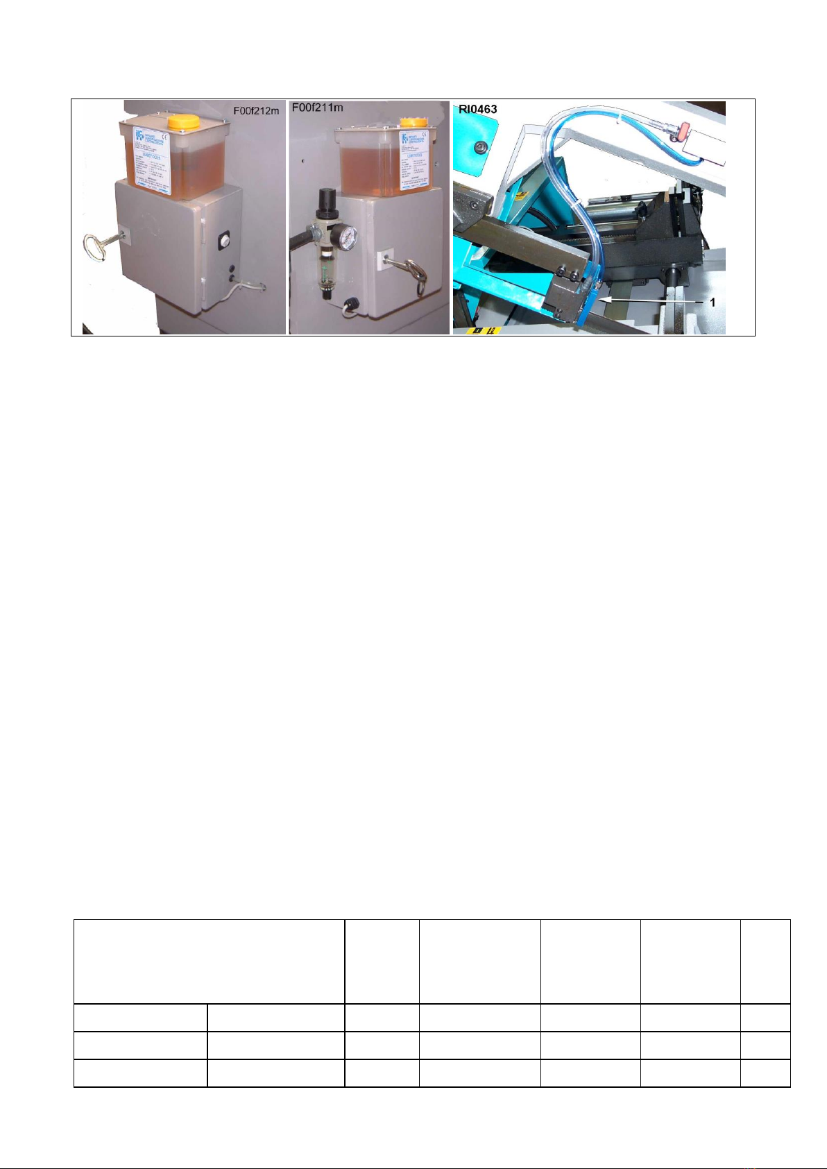
Minimal lubrication system –This device, applied to the saw, allows to eliminate almost completely the
traditional coolant system, keeps the material much cleaner and avoids to waste cutting oil and water. It
works only during the cut.
It is comprised of a nozzle - 1/RI0463 - with 3 micro-holes, a tank with devices to adjust the quantity of oil and
the air pressure. The switch of the electric system - 3/RI0462 - working with low tension 24V AC allows to turn
it off at any moment and use the normal coolant system. . Remove the nozzle 1/RI0463 to obtain the maximal
cutting capacity.
TRADUCTION OF THE ORIGINAL INSTRUCTIONS FOR USE
BS 300/60 AFI-E ED.2010 rev.00
12/61
Voltage transformer - place it between the electric supply of the premises and the electric supply of the
machine. It allows to work with a different voltage than the standard one (that is 400V / 50 Hz). Available
voltages: 230V, 460V, 500V, 575V.
BAND CHOICE
In this paragraph we recommend the type of cutting band in accordance with the material to use . To get the
best performance from this machine it is necessary to undestand the right use of the used tools and what
you have not to do with them.
The band you have to use must have the following sizes ( in mm. ) :
maximum lenght = 2770
minimum lenght = 2750
total height = 27
thickness = 0,90
Blades with a different thickness can be utilized by changing appropriately the width of the blade guides (see
the paragraph ADJUSTMENTS ) and the band tension.
The blade material is also important; generally the bi-metal blade is used, with different levels of HARDNESS,
named M42 or SVGLB (for general purpose: tube, solids and profiles, available in all pitches), M51 or
SHL (preferred for big solids of hardened steel, INOX material too, available in 3/4 and 2/3 pitch).
The teeth hardness increases - and the fragility too - by going from the material M2 to the M51.
To make a good cut it’s crucial to choose the right pitch (t) or NUMBER OF TEETH PER INCH (z). The
blade must generally have the toothing as follows:
- small teeth when cutting thin materials, tubular and profiles.
- big teeth when cutting solids or pieces with a long cutting section (for example the central part of a U
profile), or in case of softer materials such as aluminium, copper, soft bronze.
By choosing the suited pitch you can avoid a lot of mistakes and you can get a good blade penetration and
the necessary room for the chips. If you cut more pieces at the same time, you must consider them as a
single piece (that is, you have to consider the total size). The enclosed chart gives the necessary
information for a correct choice. It can however be updated or modified by the user according to his
personal experiences.
Even if there are blades with constant pitch, most bandsaws allow the use of blades with variable pitch, that
is, groups of teeth having different pitch one from each other, which reduce vibrations and noise and improve
the quality of the cut and the cutting performance.
SUGGESTED PITCH
SOLIDS
Outer
Diameter
(mm)
BIG
PROFILES
Wall
Thickness
(mm)
PROFILES
Wall
Thickness
(mm)
BUNDLE
Lenght
to Cut
(mm)
REF.
VARIABLE
CONSTANT
14 M42
-
-
1,5 max
-
10/14 M42
10 M42
-
-
1 a 2
-

TRADUCTION OF THE ORIGINAL INSTRUCTIONS FOR USE
BS 300/60 AFI-E ED.2010 rev.00
13/61
8/12 M42
8 M42
20 max
-
2 a 4
-
6/10 M42
6 M42
40 max
-
4 a 8
-
5/8 or 5/7 M42
5 M42
30 a 80
6 a 12
-
50 a 100
4/6 M42
4 M42
40 a 90
10 a 20
-
70 a 120
3 / 4 M42 o M51
3 M42 o M51
70 a 150
15 a 25
-
100 a 200
2 / 3 M42 o M51
2 M42 o M51
120 a 230
Oltre 25
120 a 300
These cutting recommendations refer to 100 mm. diameter solid bars and a standard saw of our
product range. For 2-speed machines we suggest the motor speed to use; when it’s into a bracket ( ) it is
recommended to use a machine with ESC, which grants a continuous blade speed variation.
If the size of the material decreases, the indicated figures can be increased, considering also the
machine model and its performance and/or some accessories, for example the ESC (Electronic Speed
Control):
If the material size increases, it is necessary to decrease the indicated values, considering also the
machine model and its performance and/or some accessories, such as the ESC (Electronic Speed Control):
Using manually a saw often means a significant variation of the cutting times, because of the inconsistent
down-feed speed.
MATERIAL
GROUP
i.e. DIN
denomination
DIN N°
Maximum
BLADE
SPEED
m/min
Minimum
BLADE
SPEED
m/min
MOTOR
SPEED
(1or2)
FEED
FORCE
COOL
ratio
1)STRUCTURAL
STEEL
St37 St42
10037-10042
60
40
1.
LOW
10%.
St50 St60
10050-10060
50
35
1
LOW
10%
HARDENING
STEEL
C10 C15
10301 10401
45
35
1
LOW
15%
16MnCr5 20CrMo5
17131
17264
40
30
1
Low/Me
d
10%
AUTOMATIC
STEEL
9S20 10SPb28
10711
70
50
1 2
LOW
15%
BEARING STEEL
100Cr6
13505
40
25
1
Med/Hig
5%
SPRING
STEEL
65Si7
15028
40
30
1
Med/Hig
5%
2)TOOL STEEL
UNALLOYED
C80W1
C125W
11525
11663
40
30
(1)
HIGH
5%
ALLOYED
210Cr12 X155CrVMo
12080 12379
30
20
(1)
HIGH
dry
X40CrMoV51
12344
35
20
(1)
HIGH
5%
HIGH SPEED
STEEL
S-6-5-2-2
13243
30
20
(1)
HIGH
5%
INOX STEEL
X5CrNi18 X10Cr1810
14305
30
20
(1)
HIGH
5%
3)SPECIAL
ALLOYS
NiCr19NbMo
(Inconel)
24668
20
15
--
HIGH
20%
NiMo30
(Hastelloy)
24810
20
15
--
HIGH
15%
NiCr13Mo6Ti3
(Nimonic)
24662
20
15
--
HIGH
15%
TITANIUM
Ti1
37025
30
20
(1)
HIGH
10%
G-TiAl6V4
37164
35
20
(1)
HIGH
10%
4)CAST IRON
GG15 GG30
--
50
30
1
Med/Lo
w
dry

TRADUCTION OF THE ORIGINAL INSTRUCTIONS FOR USE
BS 300/60 AFI-E ED.2010 rev.00
14/61
5)NOT-FERROUS
ALUMINIUM
AL99.5 GalSi15Mg
--
300
50
2
Med/Lo
w
2%
BRONZE
CuSn6 CuSn6Zn
--
120
40
2 1
Med/Hig
2%
COPPER
G.Cu Ke.Cu
--
200
50
2
LOW
2%
3. INSTRUCTIONS FOR USE AND WARNINGS
This machine can make automatic work cycles, however at the end of each one the operator has to remove
the material that has been cut and possibly change the cutting conditions. Therefore the saw sometimes
must be manually adjusted and then it works in automatic cycle (so the operator is not indispensable).
The working cycle ends when the machine stops; in order to begin a new cycle, the starting procedure will
have to be repeated.
This machine is designed and manufactured so as to be safely used by the operator, provided that it is
properly operated . No protections will ever suffice if the operator does not work with due caution, does not
make sure that the machine is in top operating conditions and does not follow the instructions below.
You must remember that the machine is designed to CUT METALS with a sharp tool, and you are
responsible to see that it is operated in a SAFE and CORRECT manner.
1. make sure that the machine is properly installed and electrical installation is proper.
2. be sure you are familiar with all operating, safety, and applications information before running this saw.
3. see that all who operate this machine are properly trained and fully aware of all safety practices.
4. do not expose yourself or other people to any risk.
5. insist on proper personal protective equipment and practices.
6. maintain all factory-installed SAFETY DEVICES and make sure that these are never removed or altered or
restricted in any way.
7. the operator must have a safe and organized work area with suitable light and operating room.
8. the whole equipment has to be correctly and constantly maintained and inspected on a regular basis.
9. never use tools with different features from those for which the machine is designed for.
10.never use this machine to cut material bigger than the cutting capacity.
11. keep the cutting area clear of tools or other loose objects.
12. never operate the saw unless all protections are in place.
13. NEVER WEAR loose clothing, long sleeves, large gloves, jewelry, or any other items that may be trapped
into a part of the equipment. Confine long hair.
14. always disconnect the power at source when performing maintenance or making adjustments.
15. never insert hands or arms into or near the cutting area while machine is running.
16. properly clamp the material in the vice and never hold it with your hands.
17. support suitably the bar on both sides of the machine to prevent falling.
We recommend to connect an unloading table in case the cutting length of the material is longer than the
distance between the blade and the right edge of the saw.
18. when cutting very short pieces, make sure they do not jam into the blade.
19. if the blade becomes jammed, turn immediately off the emergency locking button, then move the cutting
unit to the CUTTING START position. If this is not possible, open the vice and move the piece, check that the
blade or teeth are not broken, if so replace it.
20. never change the working conditions when cutting, with exception of those specifically allowed (for
example, changing speed with the Inverter).
21. do not move the saw while cutting and avoid its instability.
22. wear personal safety equipment, if required for a safe operation.
ALWAYS OPERATE THE MACHINE SAFELY,
USING COMMON SENSE AND ALERTNESS
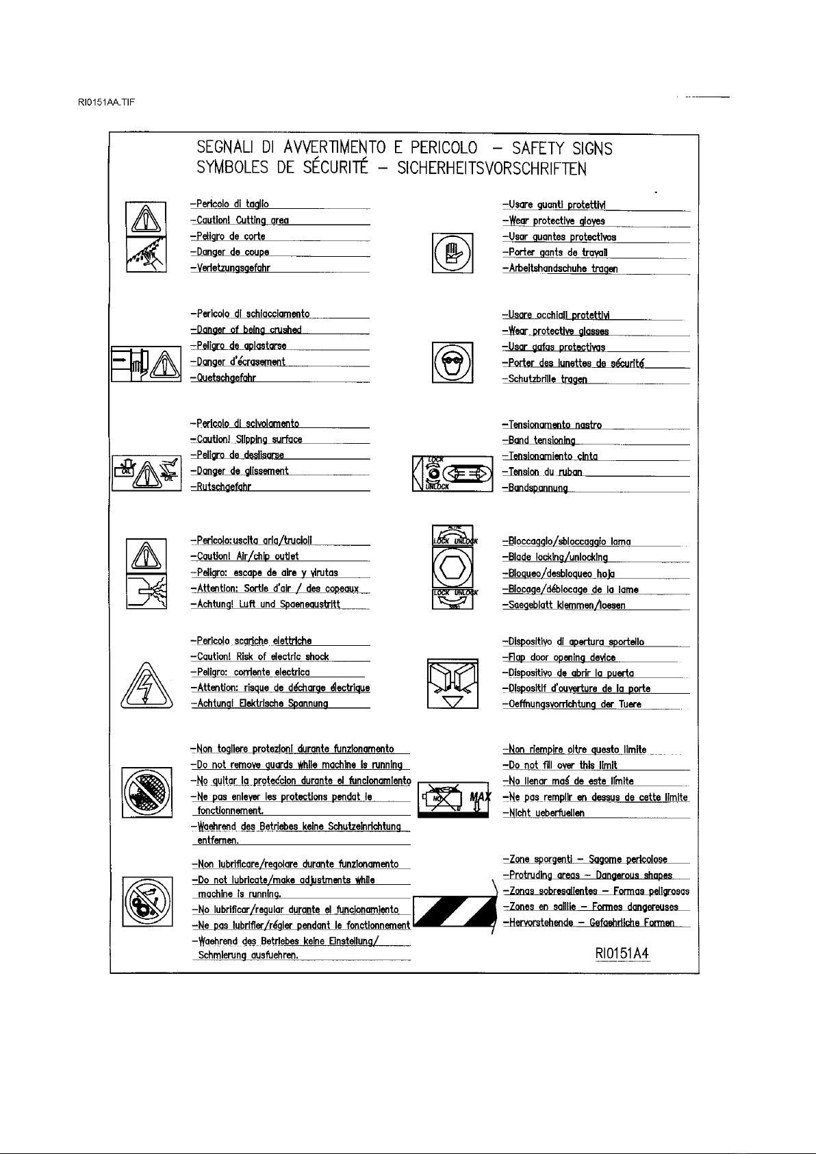
On some parts of the machine there are some stickers which warn about the safety measures that have to be
taken by the operator who runs it. Their meaning (easy to understand) is indicated in the following chart
TRADUCTION OF THE ORIGINAL INSTRUCTIONS FOR USE
BS 300/60 AFI-E ED.2010 rev.00
15/61

TRADUCTION OF THE ORIGINAL INSTRUCTIONS FOR USE
BS 300/60 AFI-E ED.2010 rev.00
16/61
OPERATOR’S SAFETY
This section illustrates the safety protections applied on the saw, according to the current legislation in the
field of safety.
3.2.1. ELECTRIC EQUIPMENT –Norm EN 60204-01
. Electric board closed with screws - general switch
. Marking of the electric components used, according to the indications on the electric scheme
. Control circuit with 24V tension –Control transformer with fuses on input and output
. Earthing of all electric parts with a dedicated GREEN/YELLOW wire, connected with a TN system to the
supply cable. A supplementary earthing point –indicated with PE –can be located on the metallic structure of
the machine.
. Minimum tension coil that prevents accidental restarting after a lack of tension.
. Protection from overloads and high temperature thanks to bimetal thermo-protectors placed directly in the
blade motor
. Emergency button for interrupting immediately all the movements of the machine. In order to restore all the
functions, rotate the button half a turn.
. Sensor of the blade tension: in case the blade breaks or the tension strength diminishes, the machine stops
immediately
. Sensor of the closing of the blade protection: if it opens during the working, the machine stops.
. The stops caused by one of the aforementioned devices needs a complete restoring of the working cycle
3.2.2 –PROTECTION AGAINST ACCIDENTAL CONTACTS
. Complete metallic protection of the blade and the pulleys, the blade-cleaning brush and the back blade-
driving pads
. Forward metallic moving guard, fixed to the forward blade-driving pad. It assures the coverage of the blade
in every position, except for the stretch of blade which makes the cut. Joint to the blade-driving pad, it can be
opened only after the opening of the main protection
. Positioning of the saw blade thanks to 2 buttons located on the control board, in order to limit the width of
the danger area to the stretch of blade strictly necessary for the cut.
. During the cycle an automatic approaching device stops the saw blade near the material, in order to start
the cut.
. Clamping vice with a maximum stroke of 7 mm, according to the norms on automatic closing
. Guard extended to both sides which retains the coolant used during the cut, preventing its spilling on the
floor
. Parts of the machine with suitably chamfered or rounded angles
3.2.5. LIGHTING OF THE WORKING AREA
An inadequate lighting can cause accidents to the operator, who consequently needs a suited lighting in the
working area. In case of a lack of precise indications (for example, norm ISO 8995) for special areas, we
advise to supply a lighting equal to 750 LUX.
MACHINE DESCRIPTION, E.C. SAFETY NORMS
Automatic electronic band sawing machine with hydraulic movement . The head swivels from 0 deg. to 60
deg. left of metal profiles and solids.
TRADUCTION OF THE ORIGINAL INSTRUCTIONS FOR USE
BS 300/60 AFI-E ED.2010 rev.00
17/61
It is not suitable for cutting wood or similar materials ( cfr.D.M. 2006/42/CE ).
It automatically makes a working cycle usually consisting of :
Locking material, approaching and cutting , tool return, unlocking material and its displacement for a new cut.
The operator has to adjust the cutting parameters , to adjust the saw frame swiveling to make the inclined
cuts , to program the strokes quantity , the lenght and the quantity of pieces, and the cycle starting .
In designing and manufacturing this machine, we have considered the requirements of the Machine Directive
(2006/42/ EEC and so on..), important document valid in all E.E.C. Countries. Furthermore we have
considered the norms as type A and B in the case that specifications of type C are not available.
The choice and the use of the parts have been made by considering the conditions of use and the long
machine life.
From the position of the work, in front of the frontal vice, the operator has the possibility to actuate the
controls and to control the good working of the machine.
In the other paragraphs you will find any informations to use the machine in the best way and for a very long
time.
Hereunder described you will find the recapitulation of the informations for the machine marking, its
identification plate is fixed on the right front angle.
The keyboard of the electronic control has a further register number placed on the back shield.
1.1 - APPENDIX FOR E.M.C.
The structure of this machine complies to the protection requirements of the EEC Directives 2004/108/EEC,
2006/95/EEC in terms of Electromagnetic Compatibility (E.M.C.) and LVD.
It especially abides by the technical prescriptions of the norms EN 55011 and EN 50082-2, and it is fit to be
used in industrial environments and not in residential ones.

TRADUCTION OF THE ORIGINAL INSTRUCTIONS FOR USE
BS 300/60 AFI-E ED.2010 rev.00
18/61
- MACHINE SETTING FOR STARTING
Verify that machine has not clear damages or faults and check upon the standard equipment that includes
the tools, fittings to do some adjustments, using and maintenance handbook .
In case the machine is supplied with additional equipment make sure that it is adaptable to the machine.
Point in good time the possible damages or faults to the reseller or to the service staff before starting
machine.
Remove the locking shaft between sawframe and base, tighten the small threaded handle placed in the hole
of the shaft base - 4/RI0461 –in order to prevent the blade guide from moving.
-. Remove the protective substances from the surfaces, used to keep the machine during the moving and
transit, by cleaning them with a non-filamentous cloth or paper and please check that there is no rust in the
metallic parts.
In case of using compressed air jet always wear proper eye protection.
Take the chip pan tank out -pos.5/dr.RI0439- by unhooking it from the guides then remove the possible dirty
that can obstruct the passage of the coolant.
The parts in motion ( band guides, trolleys, pivots, bearing support, bearing disc and so on ) are already
lubricated, the reducer gear holds the exact quantity of oil necessary to the operation.
Hydraulic system is ready to start.
If not tensioned : stretch the springs.-6/RI0439 - placed at the back side of the machine to balance the saw
frame : loosen the fixing springs of the sliding plate - and, by a lever , place it about the half of the slots.
Hardly lock the screws immediately. It is necessary to do these operations with the saw frame completely up.
8.1 - COOLING SYSTEM
Prepare the cooling by mixing the cutting oil and water ( the tank holds about 40. litres ) in proportion 1/10,
1/15 or according to the instructions of product supplier .Pour out the cooling in the tank - you can approach
it by the rear side of the floor stand - or directly on the work table - pos.4/dr.RI01..-. In this case keep attention
that the chip pan tank is correctly placed .
8.2 - ELECTRICAL CONNECTION
Verify that voltage and power frequency are compatible with numbers reported in the technical data plate (
placed on the right side of the floor stand ) difference over 10% causes some working unevenness more or
less manifested. This operation must be made by authorized , operators ( for ex. by an electrician ) .
The pashing performed by the manufacturer allows to get a right rotation of all motors by connecting the
wires in the following order L1=R, L2=S, L3=T, anyhow check as follows : ( rightly close the coverband
protections ) .

TRADUCTION OF THE ORIGINAL INSTRUCTIONS FOR USE
BS 300/60 AFI-E ED.2010 rev.00
19/61
a) If the EMERGENCY-.. - button is on , press it off and turn it 1/4 of turning in the marked direction.
b) press the button ON of the main switch- , placed on the right side of the column ; some leds of the control
panel of the control are flashing-pos. and the display shows some numbers and/or figures.
c) be sure that the manometer of the hydraulic installation-pos.4/drawing RI0426 , accessible from the door
, shows a pressure of about 12/14 BAR.
d) if it does not happen in the first 10 seconds turnf off the machine by switching off the main switch and
check the connection with the line .( Disconnect the feeding plug , reverse the connection of two of the wires
of line connection , excluding the green / yellow cable of grounding and start again from point a) .
e) Be sure that coolant is sucked in by the tank and arrives in the cutting area. ( with the taps open, by
pressing the button -pos.23/dr.RI0055- the recycling pump brings into action ).
f) Stop the working by pressing the main switch.
8.3 - BAND TENSIONING
The machine is equipped with a tensioned band and the starting of the motor is impossible if right force of
tension has not been opened up before. If it is not so:open the hinge of the cover band protection and remove
it from the supports -pos.1/dr.RI0054 - to be sure that the band ( " or blade " ) is against the pulley and it is
correctly put in the band guides head -pos.3/dr.RI0054-.
If necessary loosen a little the screw of the band stretcher-pos.4/dr.RI0054, to place again the band , then
assemble again the protection guard by being sure that the safety stroke end -pos.3dr.RI01..- is rightly
pressed.
The drawing shows the operation without the cover band protection, to only better illustrate the working area.
But it is not possible to work like this.
Press the main switch , wait for some seconds that the panel drawing RI0055 - stabilizes its workings, then
press many times the pushbutton MODE -pos.10/dr.RI0055- until the LED light marked with the "band"
symbol -pos.6/dr.RI0055- is on.
If the LED flashes , it means that the band is not tensioned : screw the frontal grub screw -pos.4/dr.RI0054-
by using the proper spanner-pos.5/dr.RI0054- , until the LED will be continuinghly flashing.
The procedure to change the blade after a change of pitch, wear and tear and break is the same one of the
above described procedure .In this case it will be necessary a careful cleaning of all points of connection with
the band.
In the following paragraph you will find the full controls list .
Table of contents
Other IMET Spa Saw manuals


Popular Saw manuals by other brands


Dake
Dake SE-5X6 RCT instruction manual

Bosch
Bosch PKS 18 LI Original instructions

Extol Industrial
Extol Industrial SHARE 20V user manual

Hafco Metalmaster
Hafco Metalmaster VB-300 instruction manual

Craftsman
Craftsman 137.407530 Operator's manual

Berner
Berner BSS1000 Instruction manual/safety instructions


