IMET Spa VELOX 350 AF-E Guide
28/11/02-\\SERVER\TECNICO\-SNZ\0Sit\hVelox350afe.doc-Scheda Identificazione Codice Padre (mac.sott.etc...)-1
di 76 pagine.
Pagina n°-
1
VELOXAFE.DOC
63A VERSION O
MI/O/03-97/0
---------------------------------------------------------------------------------------------------------------------------------------
INSTRUCTION MANUAL, MAINTENANCE AND SPARE-PARTS
(read carefully all information contained in this manual)
---------------------------------------------------------------------------------------------------------------------------------------
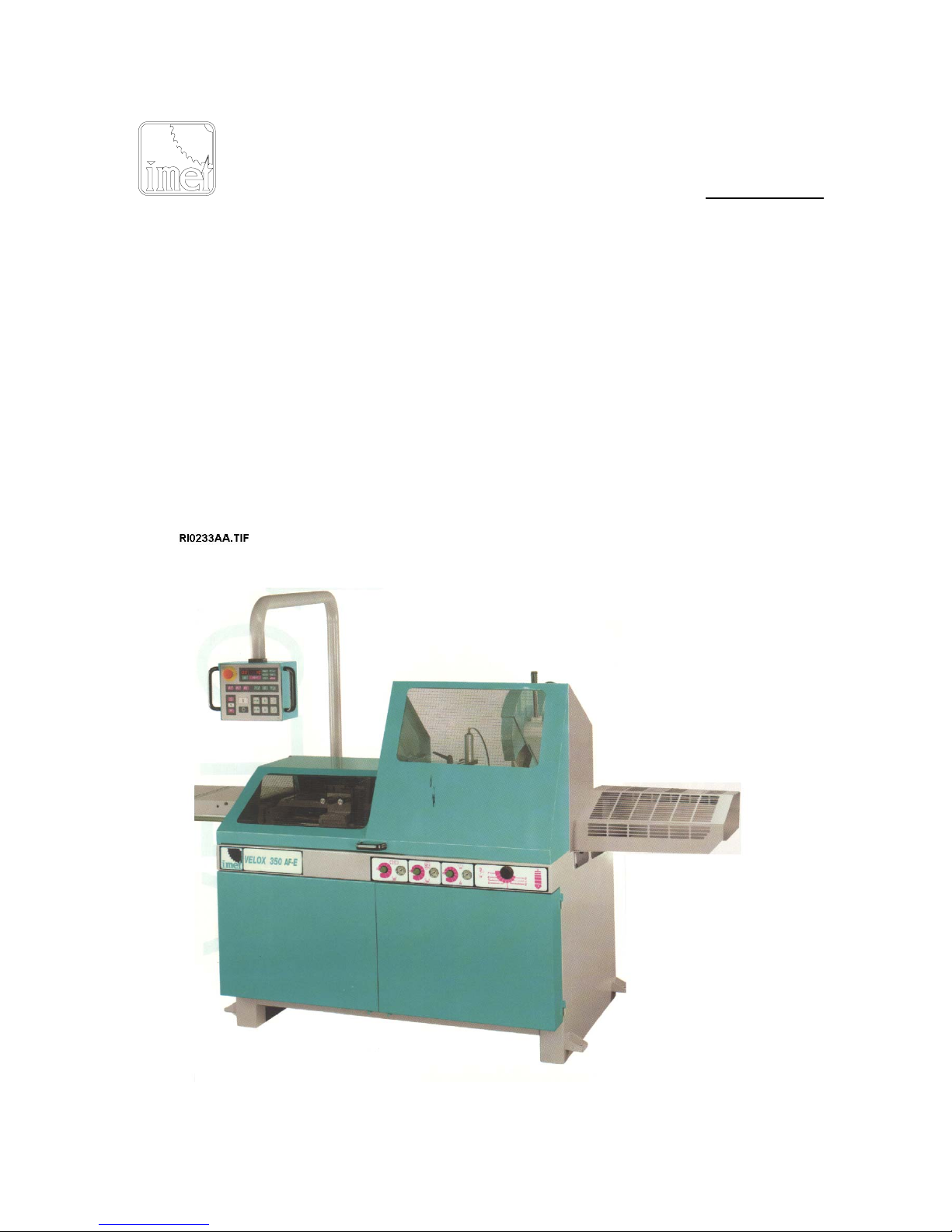
CIRCULAR CUT OFF SAWING MACHINE, RECOMMENDED FOR CUTTING ALUMINIUMN
MODEL : VELOX
VERSION : 350 AF-E (automatic-electronic)
(summery of all information foreseen for the marking: see page 3)
---------------------------------------------------------------------------------------------------------------------------------------
IMET S.p.A
Località Tre Fontane - 24034 CISANO BERGAMASCO (BG)
Tel. 035 / 787833, Fax. 035 / 787066
---------------------------------------------------------------------------------------------------------------------------------------

28/11/02-\\SERVER\TECNICO\-SNZ\0Sit\hVelox350afe.doc-Scheda Identificazione Codice Padre (mac.sott.etc...)-2
di 76 pagine.
Pagina n°-
2
63BCU
We recommend to read carefully the information here included in order to install, use and maintain correctly
and safely this machine.
Please refer always to this instruction manual in case of assistance service need and keep it carefully for all
the machine life. The reference number is shown on the cover.
A consequence of the continuous improvement of the product is that some images/descriptions here
included could not correspond to the improved features of the machines.
Your kind collaboration would help us in intevening asap.
GENERAL INDEX PAR. PAGE
1 - Machine description - applied norms - marking 63DO
2 - Technical specifications 63E1
3 - Foreseen use and controindications 63FA
4 - Moving and transit 63GD
5 - Installation - minimum requirements - 63HF
6 - Fittings assembling 63IG
7 - Blade choice 63ISF
8 - Machine setting for starting 63LH
8.1.1 - Cooling system / blade assembling SIRIO 350 AF-NC "
8.1.2 - Cooling system / blade assembling VELOX 350 AF-NC "
8.2 - Pneumatic connection "
8.3 - Electrical connection "
9 - SYSTEM STARTING
9.1 - Keyboard 63MW
9.2 - Setting of the cutting limits "
9.3 - Information on display / errors table "
9.4 - Description of the commands 63MI
9.5 - Preparation for the semiautomatic cycle "
9.6 - Semiautomatic cycle "
9.7 - Locking / Emergency locking "
9.8 - Unlocking blade (for SIRIO 350 AF-E only) "
9.9 - Head rotation for oblique cutting "
9.10 - Head inclination (for VELOX 350 AF-E only) "
9.11 - Speed mechanical gear (for SIRIO 350 AF-E only) "
9.12 - Preparation to the automatic cycle "
9.13 - Automatic cycle "
9.14 - Overload protections "
10 - Adjustments 63NP
10.1 - Air pressure for cutting unit "
10.2 - Air pressure for vices "
10.3 - General working pressure "
10.4 - Cutting speed "
10.5 - Jaws for feeder vices "
10.6 - Positioning of the hanging command "
10.7-Vice 63NQ
10.8 - Cutting head "
11 - MAINTENANCE - for the user "
11.1 - Recurrent controls "
11.2 - Blade running-in 63NRC
11.3 - Machine running-in 63NRO
12 - Defects identification 63NDO
12.1 - Caused by the machine "
12.2 - Caused by the blade "
13 - Machine noise 63PF
14 - Draining of used / produced substances 63RB
28/11/02-\\SERVER\TECNICO\-SNZ\0Sit\hVelox350afe.doc-Scheda Identificazione Codice Padre (mac.sott.etc...)-3
di 76 pagine.
Pagina n°-
3
15 - Machine demolition 63SA
16 - Guarantee norms
17 - SPARE PARTS 630A
17.1 - Norms to request the spare-parts "
17.2 - OILS AND LUBRICANTS RIO108
18 - MAINTENANCE - for qualified technicians -
18.1 - Electrical scheme (2 and 4 speeds) QE0093A4
18.2 - Hydropneumatic circuit QE0095A5
18.3 - Parts drawings RI0154A3
19 - Enclosed (EMC / CE) 63TA / 41

28/11/02-\\SERVER\TECNICO\-SNZ\0Sit\hVelox350afe.doc-Scheda Identificazione Codice Padre (mac.sott.etc...)-4
di 76 pagine.
Pagina n°-
4
63 DO
1 - MACHINE DESCRIPTION, E.C. SAFETY NORMS, SUGGESTIONS FOR THE USE
Automatic circular cut off sawing machine with pneumatic motion and hydraulic brake of the blade lowering
speed. The head swivels from 45 deg. left to 45 deg. right. It is suitable for cutting metal profiles and solids in
aluminium and light metals.
The cutting unit moves till 45 deg. from the vertical.
This machine is not suitable for cutting wooden materials or similars (cfr. D.M. 89/392, enclosure I, par. 2,3).
The cutting unit makes automatically one working cycle that consists of:
material locking, approaching and cutting, tool return, material unlocking and bar displacement for a new cut.
The operator must adjust the cutting parameters, the rotation of the head for making inclined cuts, the setting
of the lenght and quantity of pieces, the cycle start and the displacement of a new cutting bar at the end of
the one already cut.
In the enclosed declaration of Conformity you can find the Reference Directives and the Norms applied
during the designing and manufacturing of the machine.
From the working position, in front of the frontal vice, the operator has the possibility to actuate the
commands and to control the good working of the machine.
In the following paragraphs you will find all information necessary for using the machine in the best way and
for a very long time.
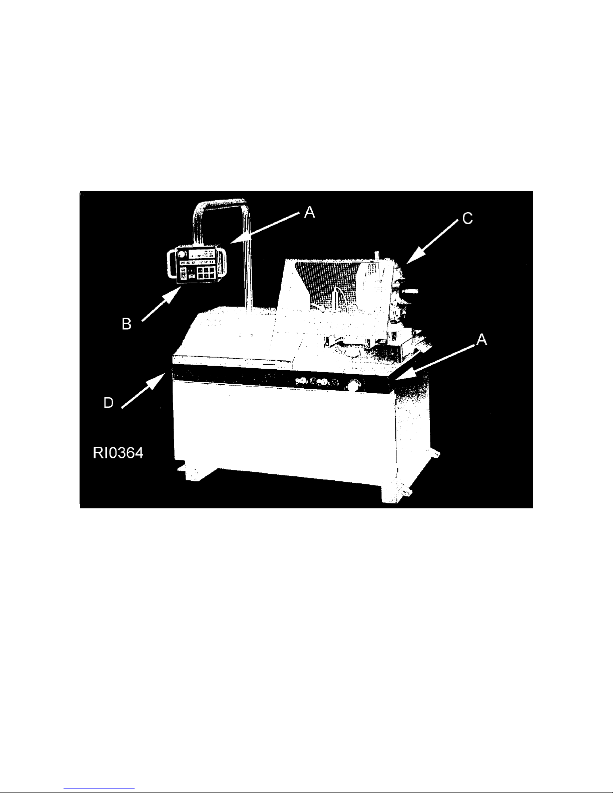
The picture no. RIO165 here enclosed sums up all indications necessary for the machine marking:
- identification plate, with the serial number, is fixed on the front right angle - pos. A ;
- the keyboard of the electronic control has a further register number placed on the back shield - pos. B ;
- each motor - pos. C, has its own serial number.
1.1 - APPENDIX FOR E.M.C.
The structure of this machine is complying to the protection requirements of the EEC Directives 89/336/EEC,
92/31/EEC and 93/68/EEC in terms of Electromagnetic Compatibility (E.M.C.).
In particular it respects the technical prescriptions of the norms EN 55011 and EN 50082-2, and it is
foreseen to be used in industrial enviroments and in residential ones.

28/11/02-\\SERVER\TECNICO\-SNZ\0Sit\hVelox350afe.doc-Scheda Identificazione Codice Padre (mac.sott.etc...)-5
di 76 pagine.
Pagina n°-
5
63 EC
The technical specifications that you will find in the following tables serve to have a general evaluation of the
machine and its performances.
If not differently indicated, all data reported in this manual refer to the standard version, suitable for
working at 400 V / 50 Hz if THREEPHASE.
From the top to the food the tables illustrate :
1) cutting capacity ( maximum possible sizes )
2) foreseen tool type
3) Type of motors to be used and tool speed.
4) exterior sizes and weight of the machine only without fittings .

28/11/02-\\SERVER\TECNICO\-SNZ\0Sit\hVelox350afe.doc-Scheda Identificazione Codice Padre (mac.sott.etc...)-6
di 76 pagine.
Pagina n°-
6
63 FA
3 - INSTRUCTIONS FOR USE - SUGGESTIONS FOR THE OWNER AND THE OPERATOR
- AUTOMATIC MACHINES -
This machine is designed and manufactured so as to be safely used by the operator, provided that it
is properly operated. No protections will ever suffice if the operator does not work with due caution,
if the machine is not kept in top operating conditions and if the instructions here below are not
respected.
The machine is foreseen to make automatic working cycles after programming/adjusting the
necessary working parameters. As a result of the adjustments you made, the machine works without
further changing till the working process is finished (unless the raw material, you have to work, is at
the end). So that there are moments in which the machine works manually, and moments in which it
works automatically (in this case the presence of the operator is not necessary or consists only of
watching the machine).
You must remember that the machine is designed to cut metals with a sharp tool, and you are
responsible to control that it is operated in a SAFE and CORRECT way. You must :
1. Make sure that the machine is properly installed and right connected to the external sources of energy.
2. Be sure you are familiar with all operating, safety, and application information before operating this
machine.
3. Do not expose yourself or other people to any risk, for example use eye glasses and gloves during the
cleaning and moving of material.
4. Use proper personal protective equipments where required.
5. Keep and do not modify all safety devices installed by the factory, and make sure that these are never
removed or altered or restricted in any way.
6. Make a regular maintenance of the machine and check often its complete working efficiency.
7. Never use tools with different dimensions than the minimum ones indicated.
8. Never cut materials with bigger dimensions than the ones indicated.
9. Keep cutting area free from tools or from other unnecessary objects.
10. Make sure that all guards are rightly placed before starting the machine on.
11. Use always clothes that cannot bring problems: Avoid wearing large sleeves, necklaces, chains, ties, too
big
gloves and any other objects that may get caught in the machine. Gather up long hair.
12. Disconnect always the plug from the supply socket during performing maintenances or adjustment
operations.
13. Never approach or insert hands or body pats into or near cutting area when the band is running.
14. Check if the workpiece is rightly locked when you are using the automatic vice closing, and if the
clamping
pressure is right.
15. Support correctly the material by both cutting sides for evoiding the fall down and / or for driving into the
discharge box.
16. If you cut very short pieces, make sure that they are not dragged by the blade and / or they do not jam
with
the blade.
17. If the blade becomes jammed, turn off power immediately by starting the emergency stop, then bring the
cutting unit to the position CUT START. If it is not possible open the vice, remove the workpiece from the
blade, check if the band or the teeth are broken, and replace it if necessary.
18. Do not change the working conditions during the cutting except for the conditions indicated in this
instruction
book (for example speed changing with ESC)
19. Do not move the machine while cutting.
20. Wear personal means of noise protection (head phones, plugs, an so on ) during the use of the
machine.
ALWAYS OPERATE MACHINE SAFELY, USING COMMON SENSE AND ALERTNESS .
28/11/02-\\SERVER\TECNICO\-SNZ\0Sit\hVelox350afe.doc-Scheda Identificazione Codice Padre (mac.sott.etc...)-7
di 76 pagine.
Pagina n°-
7

28/11/02-\\SERVER\TECNICO\-SNZ\0Sit\hVelox350afe.doc-Scheda Identificazione Codice Padre (mac.sott.etc...)-8
di 76 pagine.
Pagina n°-
8
63GD
4 - MOVING AND TRANSIT
If the machine is contained in a protection cage, after taking away the packing material, control the machine
entireness.
The weight is written on the packing outside and it is in the technical data of this instruction manual too, in
the paragraph 2.
The monobloc floor stand also allows to make the displacement with a lift truck placed at the front side (from
the position of the operator).
In this case the " forks " of the lift truck must have a length equal or superior than 1 meter.
In some versions there are some plates fixed on the 4 angles of the floor stand; hook on these plates the
end of the tools, suitable for lifting up the machine.
Make sure that lifting tools are proper for the weight and that the moving is correctly made without
unbalancing the machine.
DO NOT USE THE MOVABLE ARM WITH THE CONTROL PANEL AS LIFTING UP POINT.
In case of newt manipulations, the machine should be displaced with the saw frame (or gear head)
completely down and the feeding carriage should be placed nearly to the cutting unit (minimum stroke).
The movable arm with control panel should be blocked by the proper spacer and by the handles, which must
hinder the rotation.

28/11/02-\\SERVER\TECNICO\-SNZ\0Sit\hVelox350afe.doc-Scheda Identificazione Codice Padre (mac.sott.etc...)-9
di 76 pagine.
Pagina n°-
9

28/11/02-\\SERVER\TECNICO\-SNZ\0Sit\hVelox350afe.doc-Scheda Identificazione Codice Padre (mac.sott.etc...)-10
di 76 pagine.
Pagina n°-
10
63HF
5 - INSTALLATION
The machine can work in accordance with the parameters programmed by the manufacturer if it is rightly
installed and the minimum following requirements are observed :
- The machine must be only used in sheltered place and with a temperature from 5 ° to 40° C.
- Relative ambient moisture not over 95 % .
- Electric energy with voltage included between + - 10% of nominal value and the frequency included
between +
2% of nominal value.
- The floor must have good characteristics and must be in plane.
Overall dimensions on the floor, distances to observe and the located entry of the sources of energy are
indicated in the included drawings: RI0159 for AF-E machines or RI0319 for AF-NC machines..
The working table must be levelled: by using some screws + nuts applied into the holes of the base of
machine it is also possible to adhere the machine on the floor if necessary (for example if there are some
optionals, as RTD for ex.).
The included electric and pneumatic schemes.report the necessary data to predispose the connections that
have to tolerate a power of 4 Kw.
It is necessary to install at the supply cable a sectionalising switch specially if machine is equipped
with the outer VOLTAGE TRANSFORMER.
DIFFERENTIAL PROTECTION for models equipped with electronic variable-speed drive unit (ESC)
For the connection of the differential protection on the power supply line it is necessary to use
switches with a threshold of interference on the power dissipation of not less than 300 mA (size 0.3
A or higher is recommended), having possibly time adjustment availability ( from 0 to 1.5 sec ab.).
This machine has been foreseen for industrial and not for household use.
In the event that should be electromagnetic interferences the user is responsable for solving the problem
together with the technical assistance of the manufacturer. Before installing the machine the user must take
into account possible electromagnetic problems of the working area. In particular we suggest to install the
plant away from:
- signalling, control and telephone cables; - radiotelevision transmitters and receivers;
- computers or controlling and measuring instruments; - safety and protection devices.
-----------------------------------------------------------------------------------------------------------------------------------------------
-----
The VELOX automatic models are delivered with the movable control arm fixed inside the machine; to
position it in the normal user’s position it is necessary to unlock the cutting unit and turn it at 0° cut position,
unscrew and keep out the handle at the base of the movable control arm, turn this control arm anticlockwise
(till the user’s position), screw the handle again to fix the required position.
N.B. All the VELOX models are already supplied with a conveyor that during the cutting catches a
considerable quantity of chips / powders made by the cutting.
The tool ventilation effect is agreed with the air flow direction that a suction plant (supplied as optional, for
the models VELOX only) can produce. Anyhow the installation of a connection tube is helped by a circular
nipple placed on the back side of the machine.
For using the machine without connection tube you must consider where the machine is placed, so that you
can reduce the danger due to the thown out little pieces or dusty on the walking areas .
-----------------------------------------------------------------------------------------------------------------------------------------------
-----

28/11/02-\\SERVER\TECNICO\-SNZ\0Sit\hVelox350afe.doc-Scheda Identificazione Codice Padre (mac.sott.etc...)-11
di 76 pagine.
Pagina n°-
11
63II
- 6 - FITTINGS ASSEMBLING
The information necessary for the installation are given together with the fittings. Anyway you can find here
following a short description of the product.
Supporting roller tables: for installing these accessories in the right way it is necessary first of all to level
and fix the machine. These can be connected on both sides (loading / unloading).
For very long workpieces adhere the pedestals on the floor and recycle the coolant transported by the
workpieces that have to be cut.
Take as reference point the worktable and the support back jaw in order to aligne the roller tables starting
from the one that is nearest to the machine. If you need very long pieces fix the legs of the roller tables on
the ground and recycle the coolant transported by the workpieces that have to be cut.
If your working process require it, on the unloading side you can choose to use the roller table with manual
measuring system (RTM); the one with digital measuring system (RTD) or only the roller table(RTS) also.
Additional pneumatic front vice - It is connected to the same line that feeds the front vice, it allows the
locking of the piece from both sides only during the cutting at 0 deg.
The VELOX 350 models are standard supplied with this additional vice that can also be used for mitre cuts.
Chip suction plant - for VELOX 350 machines only - It is possible to connect it to the machine so that it
works in synchronism with the cutting movements. See the electric scheme to make such work, which
should be done by specialized persons (electricians). It is provided with a switch for the electric energy and
with a 3 mt flexible tube for the union to the coverblade carter; it’s better to reduce the tube lenght after the
choice of position has made.
" V " jaws - necessary to rightly lock the pipes until 85 mm. of diameter by avoiding the deformation. They
allow to increase the penetration speed by reducing the working time . They can only make you cuts at 0°.
Make the holes if necessary, by using the template included in the assembling kit ; assemble them by
following the instructions and place them into line by using for example a straight round, to guarantee a right
passage of the bars. During the cut they are progressively shaped by the blade: if your working process
don’t require a
complete cut, leave them attached one to the other.
Blade speed variator ESC - this electronic device is an inverter that change continuously the revolution
speed of blade motor and allows to cut a lot of different materials, from light alloys to hardened and inox
steel.
You can adjust the required speed by the pushbuttons of -1 or +2 speed on the control box. This device can
save the blade from breakage, encreasing its life because stops motor immediately when electrical
absorbtion exceeds the rated value. This optional has to be specified when you ordering the machine.
If requested electric current is more than the inverter is setted it stops immediatly, saving gear head
transmission and belt inside: usually it is caused by the extreme cutting strain, by the too high speed start-up
and so on .
Switch the main switch off, wait for about 1 minute before starting it again.
Voltage transformer - set it between the electric equipment of the building and the electric supply of the
machine. It allows to work with a different voltage than the standard one (that is 400V ).

28/11/02-\\SERVER\TECNICO\-SNZ\0Sit\hVelox350afe.doc-Scheda Identificazione Codice Padre (mac.sott.etc...)-12
di 76 pagine.
Pagina n°-
12
63 ISF
7 - BLADE CHOICE
In this paragraph we suggest the type of blade to use for cutting and the material that must be worked. To
get the best performance from this machine it is necessary to understand the right applications of the used
tools and what you have not to do with them.
The blade to be used must have the following dimensions (in mm.):
external diameter = 350 max./300 min.
hole diameter = 32 or 22 mm.
thickness = 2,5 or 3 mm. (blade in HSS steel)
thickness = from 3,2 to 4,2 mm. (blade with hard metal teeth)
Please note that the you can get the maximum cutting sizes by using the blade of maximum
diameter.
For making a right cut it is also necessary to establish the pitch ( t ) or the suitable number of teeth ( z ). The
blade must generally have the toothing as follows:
- close toothing for cutting thin materials, tubular and profiles (for example 108 teeth with a negative
inclination for reducing the noise too !;)
- thin toothing for cutting solid materials or pieces that need a long piece of blade (for example 72 or 84
teeths
with positive inclination for a better penetration inside the cutting piece);
By choosing the right one you can avoid a lot of working errors and you can get a good blade penetration
and the necessary space for the chips.
If you cut more pieces at the same time, you must consider them as one piece (that is you have to consider
the global size).
These general indications are necessary for a right choice. It can also be updated or changed by the user
according to his personal experiences.

28/11/02-\\SERVER\TECNICO\-SNZ\0Sit\hVelox350afe.doc-Scheda Identificazione Codice Padre (mac.sott.etc...)-13
di 76 pagine.
Pagina n°-
13
63LH
8 - MACHINE SETTING FOR STARTING
Check that the machine has not clear damages or faults and control the standard equipment that includes
the tools, fittings to carry out some adjustments, use and maintenance handbook.
In case the machine is supplied with additional equipment make sure that it is adaptable to the machine.
Inform immediately the reseller or the service staff about possible damages or faults before starting the
machine.
Remove the lifting plates (if present), the locking plate between the cutting unit and the floor stand, the
spacer between the movable arm and the base of the machine. Place them again inside the floor stand. For
opening the doors you have to loosen the lower hooks indicated in the picture- pos. 1 - dr. RI0345 and
RI0165-. Remove the protective substances placed on the surfaces during the moving and transit by using
cleaned and non-filamentous clorth or paper, and please check that there is no rust on the metallic parts.
In case of using compressed air jet always wear proper eye protection glasses.
Take out the chip tray from the right side of the floor stand and remove the possible objects that can obstruct
the passage of the coolant.
The parts in motion (band guides, trolleys, pivots, bearing support, bearing disc etc. ) are already lubricated,
the reducer gear of the SIRIO 370 has the exact quantity of oil necessary for working.
The pneumatic equipment, ready to start, includes an automatic lubricator capable to regulate the quantity of
oil put in the circuit -dr.RI0344-.
Then go on as follows:
8.1.1. - COOLING SYSTEM and BLADE ASSEMBLING SIRIO 370 AF-E
Prepare the cooling by mixing the cutting oil with water (the tank contains about 15 litres) in proportion of
1/10, 1/15 or according to the instructions of the supplier of the product. Pour out the obtained fluid in the
tank from the back side of the floor stand - or directly between the work table and the base -pos.17/dr.
Ri0345-.
In this case check that the chip tray and the tank are rightly placed.
Choose the blade caracteristiques following the indications of the previous table
Unscrewing the little screw and remove the transparent part of the coverblade guard -pos.2/dr.RI0329- and
the front sliding guard -pos.1/dr.RI0329 after.
Unscrew the screw -pos.1/dr.RI0062 with right thread, remove the parts-pos. 2 and 3/dr.RI0062 and keep
that the support surfaces are clean.
Move back the nozzle of coolant -pos2/dr.RI0326- and the blade brush -pos.1/dr.RI0326 by unscrewing
their screws;
to make it easy, probably you have to slide up/down the gear head by the pushbuttons of control panel: by
this, mount the blade after the electrical and pneumatic connections are made
Put the blade -pos.4/dr.RI0062- by guiding the teeth in the rotation direction shown by the PRINTED
ARROW -pos.5/dr.RI0326- on the coverblade guard and make the blade holes agree with the holes of the
fixed flange -pos. 5/dr.RI0062-.
Reassemble the closing flange -pos.3/dr.RI0062, the spring -pos.2/dr.RI0062 and the screw po-
pos.1/dr.RI0062-. Before tighting the screw, please wheel the blade forward ( in the clockwise sense ) to
cancel the being shake between the driving pin and the holes
Adjust the position of the nozzle and of the blade brush, then lock their screws, see dr. RI0327.
Replace in its place the transparent protective part and the frontal sliding guard.
8.1.2. - COOLING SYSTEM and BLADE ASSEMBLING VELOX 350 AF-E
If necessary, by following the instructions of the supplier, prepare the coolant suitable for the cutting material
because in some cases we suggest to cut by dry method. Fill the tank as above described for the model
SIRIO 370 AF-E.
Choose the blade following the instructions indicated in the previous paragraph. Rotate backsides the
movable carter -pos.1/dr.RI0069- (inside of the fixed carter - pos.2/dr.RI0069) by loosing the outside arm-
pos.3/dr.RI0069. Through the hole of the carter, with the tube spanner of 22 mm., unscrew the screw -
pos.1/dr.RI0070 of the left thread, take out the parts pos.2 and 3 dr.RI0070- and keep clean the supporting
surfaces. Insert the blade on the spindle - pos.5/dr.RI0070 - by guiding the teeth towards the PRINTED
ARROW - pos.2/dr.RI0069- placed on the carter.

28/11/02-\\SERVER\TECNICO\-SNZ\0Sit\hVelox350afe.doc-Scheda Identificazione Codice Padre (mac.sott.etc...)-14
di 76 pagine.
Pagina n°-
14
Mount again the closing flange - pos.3/dr.RI0070, the washer - pos.2/dr.RI0070, and the screw-
pos.1/dr.RI0070-. To tighten strongly this screw it is necessary to slip in a little pin (for example one of
the supplied allen spanner ) in the hole placed under the spindle so that the blade holder shaft cannot
rotate.
Replace the movable carter - pos.1/dr.RI0069 - in the initial position and fix it with the outside arm -
pos.3/dr.RI0069.
8.2 - PNEUMATIC CONNECTION
The machine is supplied with the air treatment unit -dr. RI0344-, but it isbetter to connect it to a system
provided at least with condensate discharger, with pipes correctly setted, at least with a pressure of 7/8 BAR.
The consumption of air is about .6.Nl max. for each automatic full stroke cycle.
The air filter-pos.4/dr.RI0344- has an automatic valve that cleans itself each time the air is
connected/disconnected; the lubricator -ops.4/dr.RI0344- has a little screw that by a screwdriver can be
adjusted to mix the right ratio of oil into air ( ab.one oil drop each 10/15 working cycle). To refill it, see OIL &
LUBRICANT chart to find the right one.
8.3 - ELECTRICAL CONNECTION
Verify that the voltage and the power frequency are compatible with the numbers reported on the plate with
technical data (it is placed on the right side of the floor stand); a difference over 10% causes some working
irregularities more or less manifested.
Connect the switch to a suitable socket CEE or replace it with that of normal use. We suggest you to
let do this work to specialized persons (for example to electricians). The phasing performed by the
manufacturer allows to get a right rotation of all motors by connecting the wires in the following
order L1=R, L2=S, L3=T, anyway check as follows: (compressed air inserted, pressure not lower than
2 BAR, feeder-guard-pos. 3 / dr.RI0092- rightly closed )
a) if the EMERGENCY BUTTON is off, turn it on by rotating it 1/4 of turning in the indicated direction -
pos-3 / dr.RI0345.
b) push the button ON of the main switch placed on the side of the electric control, on the back side of the
machine - pos. 2 / dr.RI0346 - (some lights turn on and the display -pos.4/dr. RI0345- shows numbers
c) Verify that the selector - pos. 1/ dr. RI0346 - placed under tha main switch is on position “MARCIA” (for
model
SIRIO 370 AF-E only)
d) Choose the motor speed by pushing the button -1 - pos. 11/dr. RI0055 -.
e) Turn on O the cutting speed regulator - pos. 2 / dr. RI0345 or RI0165 -.
f) Close completely the vice of the cutting unit and open for half turn again.
g) Push the white button I of CYCLE START - pos. 20 / dr. RI0055 - and control that the spindle rotates in
the
direction of the PRINTED ARROW placed on the coverblade.
If case the vice is not closed, you can read on the display the message of error ER0028 (see the following
paragraph 9.3) and the spindle does not rotate.
For safety take out the blade and the flanges - pos. 1, 2, 3, 4, 5 / dr. RI0070 - from the spindle of
model VELOX 350 AF-E before pushing the button I (START).
In case the blade is rotating in the opposite direction, turn the machine off by pushing the general switch -
pos.2/dr. RI0346 -, disconnect the feeder plug, invert the connection of two of the wires of the line
connection, except for the green / yellow grounding cable and start again from point b).
h) Be sure that the cooling is sucked in by the tank and that it reaches the cutting area (by turned on tap and
only if the coolant pump is started).
h) Stop the working by pushing the black button (0) - pos.21 / dr.RI0055 -.
If the EXTERNAL VOLTAGE TRANSFORMER is supplied too, place it in carefully and safely, far from
the loading/unloading areas.
In the following paragraph you will find the list of all controls.

28/11/02-\\SERVER\TECNICO\-SNZ\0Sit\hVelox350afe.doc-Scheda Identificazione Codice Padre (mac.sott.etc...)-15
di 76 pagine.
Pagina n°-
15

28/11/02-\\SERVER\TECNICO\-SNZ\0Sit\hVelox350afe.doc-Scheda Identificazione Codice Padre (mac.sott.etc...)-16
di 76 pagine.
Pagina n°-
16
63 MW
9 - SYSTEM STARTING
By turning on the system, the display shows the release software code (example 3.5) during the loading of
the set up data from the permanent memory "Eeprom". Then, for a time of about 2 seconds, it shows the
identification code of the machine (for example 28A, SIL, or something else).
For going on it is necessary to push the button - pos. 19 / dr. RIOO55 - (=CLOSE THE VICE) that
activates the oil pump - in the hydraulic models - or that allows the flux of compressed air- in the
hydropneumatic models-.
Please note that in some previous models the starting can be activated by pushing any other button.
If you push other buttons the display shows the error message: ER0034.
If you do not push any other button within 10 minutes, the electronic control deactivates the oil pump - in
hydralic models -, or it stops the compressed air - in the hydropneumatic models-. For starting up the system
push again the button -pos..19/dr.RI0055- (=Close the vice) the display shows for an instant a series of led
lights-.
After this operation the system is ready to work.
The led lights appearing on the keyboard show the operative functions of the machine.
Sometimes, after starting the machine or following to some “caused anomalies” (for ex. the blade is not
tensioned during the moving), the keyboard shows diagnostic error codes. In that case, please, refer to the
enclosed errors table (paragraph 9.3.2) for the identfication of the kind of error.
Push any button to cancel such errors, after removing the anomaly.
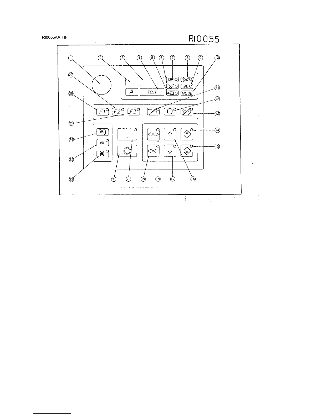
9.1 - KEYBOARD / Description and use of the buttons - See drawing RI0055
Pushing the FEED-BACK buttons made with polyester support and IP65 protection, you can program all
machine operations, including the positioning of the cutting unit :
BACKWARD (16): to remove the cutting unit from the workpiece up to the maximum programmed point. The
led light shows that the tool is moving. By pushing TEST + 16 you can get the barfeed forward.
For automatic machine only, if you press it within the TEST button -pos.4/dr.RI0055- it move the feeder
backward.
FORWARD (17): to move the cutting unit in the direction of the workpiece up to the minimum programmed
point. The corresponding led light shows that the tool is moving. By pushing TEST + 17 you can get the
barfeed return.
For automatic machine only, if you press it within the TEST button -pos.4/dr.RI0055- it move the feeder
forward.
CUT START SETTING (14): after positioning the tool by buttons 16 and 17 in the right point of start of the
controlled feed (end of fast feed/cutting start) keep the button 14 pushed for about 3 seconds, in order to
memorize the changing point from the rapid approach speed to the slow cutting speed (cutting start).
The confirmation that the memorization has been done, is shown by the symbol P¯ followed by some
numbers appearing on the display - pos. 2 / dr. RI0055.
If the led light flashes, it means that the inserted point of cutting start is not operative anymore: lighty move
the head up and memorize it again
When the led light in on, the cutting unit is on the programmed position. On the contrary, when this light is
off, the cutting unit is under the programmed position.
CUT END SETTING (15): after positioning the tool by buttons 16 and 17 in the point of end of the controlled
feed (end cut) push the button 15 for about 3 seconds, in order to memorize the changing point of: speed
end of controlled speed and cutting unit return.
The confirmation that the memorization has been done, is shown by the symbol P_ followed by some
numbers appearing on the display - pos. 2 / dr. RI0055.
If the led light flashes, it means that the inserted point of cutting start is not operative anymore: lighty move
the head down and memorize it again
When the led light is off, the cutting unit is over the programmed position. On the contrary, when this light is
on, the cutting unit is under the programmed position.
OPEN VICE (18): push it to open the machine vice. The led light on indicates that the command has been
set ( ex. when the cycle starts by open vice, the vice will open again at the end of the working cycle).
For automatic machine only, if you press it within the TEST button -pos.4/dr.RI0055- it open the feeder vice
CLOSE VICE (19): push it to close the machine vice. The same as for the open vice (see above).

28/11/02-\\SERVER\TECNICO\-SNZ\0Sit\hVelox350afe.doc-Scheda Identificazione Codice Padre (mac.sott.etc...)-17
di 76 pagine.
Pagina n°-
17
For automatic machine only, if you press it within the TEST button -pos.4/dr.RI0055- it close the feeder vice
CYCLE START(20): it allows to start a semiautomatic cutting cycle (when the led light of the function F3 is
not flashing - pos. 25 / dr. RI0055).
On request we can also programme the machine so that this button is not operative (for ex. by
connecting the command to the pedal), in order to avoid unwanted startings (ask it to Service
Assistance).
The corresponding led light indicates that the machine is working.
CYCLE STOP (21): it allows to stop the semiautomatic or automatic cutting cycle in each moment and to
push other buttons of the manual commands.
FUNCTION 1 = F1 (26): If the led light is on, the returning stroke can be done with the tool in movement; if it
is off with the tool stopped.
FUNCTION 2 = F2 (27): it allows only the slow cutting stroke, if the led light is on (short cycle); it allows the
approaching + slow cutting stroke if the led light is off (normal cycle).
FUNCTION 3 = F3 (25): if led light is on, it stops the semiautomatic cutting cycle on the returning point (at
the end of the cut).
TOOL SPEED -1 (11): by pushing this button when the machine is not working you can pre-select the lowest
cutting speed (only for 2 speed machines); if pushed when the tool is in movement there is a speed
decrease (only in machines with ESC). If the led is on, it means that the preselection has been made.
TOOL SPEED 0 (12): by pushing it when the machine is not working you can pre-select cutting speed 0. For
safety the function is not operative when machine is working. The led light on indicates that pre-selection has
been made.
TOOL SPEED+2 (13): by pushing it when the machine is not working you can pre-select the highest speed
(only for 2 speed machines); if pushed when the tool is moving, it determins a speed increase (only in
machines equipped with inverter = ESC). The led light on indicates that pre-selection has been made.
COOLANT ON IN SEMIAUTOMATIC CYCLE (24): by led light on the coolant pump is operative only in the
semiautomatic cutting cycle.
It is better if the working cycle time is longer than 15 seconds.
COOLANT ON (23): by led light on, the coolant pump is always operative.
Use only if the working cycle time is shorter than 15 seconds.
If the machine is not working you can use the cleaning gun by pushing this button.
COOLANT OFF (22): by led light on, the coolant pump is always off, for example by dry cuttings or by
setting up the machine.
Please note that these three keys can command the function of the chip conveyor in our machines for
aluminium ( VELOX) if the connection of this OPTIONAL is done according to the electrical scheme
enclosed in the instructions.
TEST (4) = Special functions for diagnostic
MODE (10) = Special functions for programming
9.2 - SETTING OF THE CUTTING LIMITS
The feed movement of the tool is limited by four programmable positions, two of which are memorized by the
manufacturer, in order to grant a correct and safe use of the machine:
1 - "MAXIMUM POINT OF RETURN” selected in the factory by pushing the key (10) + (16) together and
then
memorized by pushing the key (4) + (14) together for 3 seconds.
2 - “CUT START POSITION” according to worker choice: push the buttons (16) or (17) for moving the
cutting unit and then the button (14) for memorizing the position.
3 - “CUT END POSITION” according to worker choice: push the buttons (16) or (17) for moving the
cutting unit and then the button (15) for memorizing the position.
4 - “MAXIMUM FORWARD STROKE” selected in the factory by pushing the key (10) + (17) together and
then
memorized by pushing the key (4) + (15) together for 3 seconds.

28/11/02-\\SERVER\TECNICO\-SNZ\0Sit\hVelox350afe.doc-Scheda Identificazione Codice Padre (mac.sott.etc...)-18
di 76 pagine.
Pagina n°-
18
These limits are memorized according to the logical order (MAXIMUM POINT OF RETURN > CUT
START > CUT END > MAXIMUM FORWARD STROKE).
The position 1 selected by the manufacturer corresponds normally to the 80% of the maximum
cutting height allowed (because the machine is fast never used at 100%).
If you have to change the positio (1) do as follow: push the button (16) and at the same time the button (10);
when you reach the maximum position allowed, memorize by pushing for 3 sec. about the buttons TEST+
(14).
In the same way you can change the position (4) too (by pushing the buttons 17 + 10 an afterTEST + 15).
In case of eventual errors you can read on the display the word “bAd”instead of the confirmation of
the datum that should be memorized. It is necessary to move the cutting unit till you are in the point of
DOWN FEED / RETURN and then repeat the memorizing process; when you are in this point le
corresponding led light lights on.
It is possible to make a cutting cycle excluding the rapid approach and the cutting end and without changing
the selected points of CUT START / CUT END, as follows:
a) Push the button (14) till the corresponding led light flashes
b) Push the button (15) till the corresponding led light flashes
c) Start a cycle: the cycle starts slowly from MAXIMUM POINT OF RETURN to MINIMUM POINT OF DOWN
FEED. You can stop the cycle in each point by pushing the button (21).
You have to repeat these operations if you want to make again another cutting cycle without limits.
9.3.1 - INFORMATION ON DISPLAY /1 = functioning parameters
The key MODE (10) allows to display a series of data concerning the functioning of the machine. If you push
this button for an instant, a led light, corresponding to one of the five parameters of the machine, lights on
and you can read automatically on the display a value. If you push again MODE the following led lights,
corresponding to the other paramets, light on clockwise. The parameters are the following:
MACHINE CYCLE TIME = by led light (5) on. The display is in seconds "S" (more often), in minutes "n" or in
hours " ". Please note that the indicator adapts itself automatically to the passed time.
FUNCTIONING TIME OF THE MOTOR BLADE = by led light (6) on. Display as in “MACHINE CYCLE
TIME”. The usual case is “ “ (on hours).
For band sawing machines this led light flashing indicates that there is a wrong or insufficient tension of
the band.
NUMBER OF CUT PIECES = by led light (7) on. Progressive display of numbers from 1 to 9999, and
following appearance of the points next to the numbers, that is from 1. to 9.9.9.9.
CUTTING SPEED PREVIOUSLY SET = by led light (8) on. In meters/minutes for bands (optional in
feet/minutes); in r.p.m. for circular blades and discs.
ELECTRICAL ABSORPTION = by led light (9) on. Maximum current load in Ampere pointed out in each
cutting cycle.
Each one of these parameters can be zero-set by pushing the keys TEST + MODE together for about
2 seconds, while the corresponding light is on.
The display (2) indicates constantly the electric motor absorption in Ampere, and by reading it together with
the display (3), you can get ERROR MESSAGES.
9.3.2. - INFORMATION ON DISPLAY / 2 = Errors table (SELF-DIAGNOSTICS)
The machine is equipped with self-diagnostics function, that allows to find out the working anomalies of the
machine and to inform the worker giving the code numbersindicated here below (the ones printed in bold
type are the most frequent):

28/11/02-\\SERVER\TECNICO\-SNZ\0Sit\hVelox350afe.doc-Scheda Identificazione Codice Padre (mac.sott.etc...)-19
di 76 pagine.
Pagina n°-
19
DISPLAY ANOMALIES
ER0001 error in the configuration EEPROM
ER0002 error in the data checksum in EEPROM 1 1st. block
ER0003 error in the data checksum in EEPROM 2 2nd. block
ER0004 error in the data checksum in EEPROM 3 3rd. block
ER0005 error in the saved data in the permanent memory
ER0020 emergency active (emergency pushed?)
ER0021 motor overload protections (overheated motor?)
ER0022 open carter
ER0023 broken band
ER0024 FREE
ER0025 blocked inverter (motor under stress?)
ER0026 too high motor absorption
ER0027 not correct position of the tool for starting the cutting cycle (blade locked in the workpiece?)
ER0028 vice pressure problem (vice too open/oil pressure?)
ER0029 blade unblocking -for SIRIO models only-
ER0030 bar end - in automatic cycle - (end of the material?)
ER0031 carriage not in correct position - for starting the automatic cycle -
ER0032 feeder vice (vice too open/closed?)
ER0033 piece counter selection on 0 (for automatic cycle)
ER0034 OIL PUMP DEACTIVATED - for hydraulic models - or DISCONNECTED AIR - for hydropneumatic
models
ER9999 overflow in the machine timer (it is necessary to switch the system off and then on).
Remove the causes of the anomaly and push any other key to cancel the display code.
9.3.3. - SPECIAL FUNCTIONS of the key MODE (for qualified technicians or assistance staff only)
If you keep pushed the button MODE (10) for more than 3 seconds, you can enter a diagnostics menu
used for the technical assistance.
In this function all LED lights corresponding to the key MODE are on.
If you want to get out from this situation you have to push again the button MODE for 3 seconds.
The parameters consultation is always made by pushing for an instant the button MODE; the display shows:
P1 - historical piece counter of the machine
P2 - hour counter of the band motor functioning
P3 - current position of the blade
P4 - maximum point of the blade’s return (UP)
P5 - maximum point of the blade’s apprach (DOWN)
P6 - point of cutting start
P7 - point of cutting end
9.3.4. - SPECIAL FUNCTIONS of the key TEST (for qualified technicians or assistance staff only)
If you push the key TEST (10) together with the button COOLANT ON (23) you can enter a menu used
by the technical assistance (the display shows: IN, DAC, .., and so on in case you push any bottons).
If you want to get out you can switch the machine off and then on, or you can push again TEST +
COOLANT ON.
28/11/02-\\SERVER\TECNICO\-SNZ\0Sit\hVelox350afe.doc-Scheda Identificazione Codice Padre (mac.sott.etc...)-20
di 76 pagine.
Pagina n°-
20
Table of contents
Other IMET Spa Saw manuals


Popular Saw manuals by other brands

ICS
ICS 603GC Operator's manual

Chicago Pneumatic
Chicago Pneumatic RP9882 instruction manual

Husqvarna
Husqvarna MC 18 9H Spare parts & operator's manual

Black & Decker
Black & Decker Firestorm FS1300CS instruction manual

Greenlee
Greenlee Fairmont H4645 Operation, service and parts manual

Milwaukee
Milwaukee M18 FBS85-0C Original instructions

Milwaukee
Milwaukee M18 FUEL 2830-20 Operator's manual

Scantool
Scantool SC 125V user manual

Wen
Wen 3705 Operator's manual

EINHELL
EINHELL TE-TS 2025 UF/S operating instructions

Black & Decker
Black & Decker BD 227 operating instructions

Parkside
Parkside PGHSA 20-Li A1 Translation of the original instructions


