IMET Spa BS 300 PLUS SH User manual
TRADUCTION OF THE ORIGINAL INSTRUCTIONS FOR USE
BS300 Plus SH ED.2010 rev.00 1/53
IMET Spa
Loc. Tre Fontane - Cisano Bergamasco
Tel. 035/4387911 - Fax. 035/787066
Web site: www.imetsaws.com
E-mail: imet@imetsaws.com
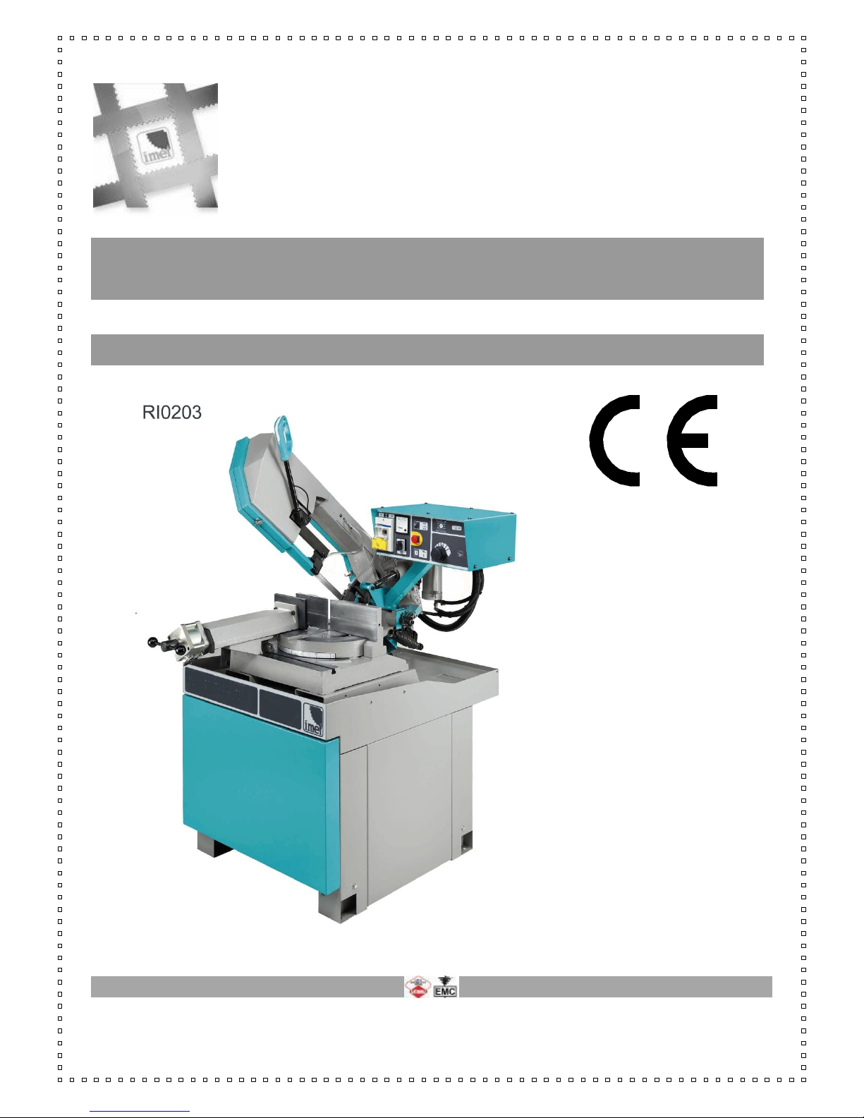
Bandsaw BS 300 PLUS SH
Semiautomatic - Pneumatic
INSTRUCTIONS FOR USE
INSTRUCTIONS FOR USE
BS300 Plus SH ED.2010 rev.00 2/53
We recommend to read carefully the information here included in order to install, use and maintain correctly
and safely this machine.
Please refer always to this instruction manual in case of assistance service need and keep it carefully for all
the machine life. The reference number is shown on the cover.
A consequence of the continuous improvement of the product is that some images/descriptions here included
could not correspond to the improved features of the machines. Your kind help would allow us to offer a
prompt assistance.
In the enclosed Compliance Declaration you will find the Safety and Reference Norms applied during the
planning and construction of this machine. The choice and the use of the parts have been made considering
the conditions of use and the long machine life.
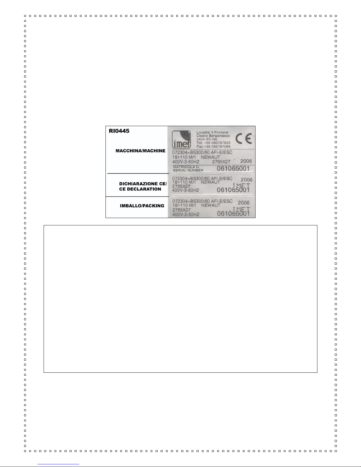
The identification plate, with the serial number, is placed on the side of the machine or on the control panel
1.1 - ATTACHED DOCUMENT FOR E.M.C. ( INDUSTRIAL ENVIRONMENT)
The user is responsible for the installation and use of this machine in compliance with the manufacturer's
instructions shown in this manual. This equipment meets the protection requirements in accordance with the
Directives 2006/42/EEC, 2004/108/CE for Electromagnetic Compatibility (EMC). In particular, it follows the
technical guidelines of the Directives EN55011, EN50082-2 and it has been made for industrial and not for
household use.
In the event of electromagnetic interferences the user is responsible for solving the problem with the help of
the technical assistance by the manufacturer. Before installing the machine the user must take into account
possible electromagnetic problems of the working area. In particular, we suggest to install the machine away
from:
-signalling, control and telephone cables;
-radio-television transmitters and receivers;
-computers or controlling and measuring instrument;
-safety and protection devices.
The electric supply cable must be kept as short as possible, without any twists.
Covers, doors and the frame must be suitably closed when the saw is operating.
Under no circumstances the machine must be modified except for adjustments and changes specifically
approved by the manufacturer. Follow the maintenance schedule.

INSTRUCTIONS FOR USE
BS300 Plus SH ED.2010 rev.00 3/53
===========================================================================
CE DECLARATION OF CONFORMITY (encl. II A DIR 2006/42/CE) / 01
===========================================================================
THE MANUFACTURER : IMET S.p.A
Località Tre Fontane
24034 - CISANO BERGAMASCO –BG- ITALIA
HEREBY DECLARES THAT
in designing and manufacturing the machine described here below , we have considered the most important
requirements of safety and health dictated by the European Directives of the Machine Security. Remember
that this declaration loses its validity if machine is modified without our agreement.
Trade name BAND SAWING MACHINE FOR METALS
Code / Model / Type
Manufacturing year
Serial number
IT IS IN COMPLIANCE WITH THE DIRECTIVES
DIRECTIVE 2006/42/CE OF THE EUROPEAN PARLIAMENT AND OF THE COUNCIL OF THE
17TH/05/2006 REGARDING THE MACHINES AND THAT MODIFIES THE DIRECTIVE 95/16/CE;
DIRECTIVE 2004/108/CE OF THE EUROPEAN PARLIAMENT AND OF THE COUNCIL OF THE
15/12/04 REGARDING THE ELECTROMAGNETIC COMPATIBILITY -EMC-
DIRECTIVE 2006/95/CE OF THE EUROPEAN PARLIAMENT AND OF THE COUNCIL OF THE
12/12/06 REGARDING ELECTRICAL EQUIPMENT FOR USE OF LOW VOLTAGE -LVD-
HARMONIZED STANDARDS REFERENCE EN.12100-01; EN 55011, EN50082-2, EN 13898, EN
60204 LEGISLATIVE DECREE N.17 OF THE 27TH OF JANUARY 2010.
AND AUTHORIZING THE PERSON LISTED BELOW TO ISSUE THE TECHNICAL FILE.
Date : 01.01.2010
The signatory identification The manager
Angelo Meroni
--------------------------------------------------------------------------------------------------------------------------
File : Machine no. Delivery note no Dated
…………………….
………………..
………………..

INSTRUCTIONS FOR USE
BS300 Plus SH ED.2010 rev.00 4/53
---------------------------------------------------------------------------------------------------------------------------

INSTRUCTIONS FOR USE
BS300 Plus SH ED.2010 rev.00 5/53
3 - MACHINE NOISE
The noise level of the working area - given the conditions described below - is determined by the
simultaneous working of several parts of the machine in motion (according to the working cycle), in addition
to the tool when cutting the material.
The noise level is detected in different moments, corresponding to different working phases. The proper
device is placed about 1 meter near the machine and about 1,60 m above the floor. The results of
each test is in dBA and they are the average of 3 tests made from the left side, opposite side and
right side.
For any machines the working conditions are the following:
When idle, at the maximum blade speed: dBA 63
During the cut, at a suited blade speed, cutting solid steel (St12=≈C20, 80mm diameter): dBA 75
(tolerance ± 2dB).
In the standard production the test is made on a machine like this, in compliance with E.C. safety norms
2006/42/CE and EN13898. Using the saw in bad conditions or using wrong tools causes significant
alterations of these tests and it jeopardizes the health of the staff and the good results of the work. Useful is
the European Guideline 2003/10/CE.
The noise depends mostly on the cutting material, on its size and on the clamping. Considering that the
above mentioned decibels could be exceeded, we recommend the operator to use personal protections
(headsets, plugs, and so on) when working for a long time with high noise levels.
3.1 - ADDITIONAL HEALTH AND SAFETY REQUIREMENTS
The machines manually controlled by an operator during all work phases must comply to further health and
safety requirements as specified by article 2.2 of the Annexed I of the European Directive 2006/42/CE and
following integrations. In particular, the level of the machine vibrations when working must be clearly specified
in the instructions.
This machine does not produce vibrations higher than 2.5 m/s2
The measurement procedure is in compliance with the general norms applied to this type of machinery.
As in the previous paragraph, using the machine in unsuitable conditions or using the wrong tools
can cause changes affecting this value, causing a risk to the health of the working staff as well as the
quality of the production. Useful is the European Guideline 2002/44/CE.
Vibrations produced during the cut may be amplified by the material, by its dimensions and its
positioning/clamping in the vice.

INSTRUCTIONS FOR USE
BS300 Plus SH ED.2010 rev.00 6/53
4 - GUARANTEE NORMS
I.ME.T. offers a wide range of sawing machines and accessories, destined to who buys/uses them as part of
a commercial or professional activity.
The manufacturer grants that this product has been strongly controlled and that there are no defects in the
used and working materials for a period of 12 months from the date of the delivery note.
The Italian law D.L. n° 24 issued on 02/02/2002 and valid since 23/03/2002 (which carries out the European
Directive 1999/44/CE) indicates different terms only for convenience products for private use.
If the user points out some defects to the manufacturer during the warranty time, the manufacturer will
replace the components that are considered faulty.
In case of reparation of the machine during the warranty time the shipment will be accepted only if the
delivery is Free Destiny (that is the freight costs are supported by the owner of the machine), and the return
of the machine to the customer is considered EX WORKS.
If the manufacturer is not able to replace a component within an acceptable time, both companies
(manufacturer and user) will reach an agreement to satisfy completely the needs of the user.
The a.m. warranty is not valid in case of accidental damages, or defects provoked by a wrong use or
maintenance of the machine, by variations made on the equipment, or by the use of the machine in a place
not corresponding to the indicated environmental specifications.
4.1 - The manufacturer does not offer further warranties, written or spoken, explicit or implicit of its products
and does not offer implicit warranties on suitability for particular uses not foreseen by the agreement or on
chances of selling them.
The a.m. limitations and exclusions can also be not applicable in Countries, where there are no implicit limits
of warranty time on the products. Anyway each implicit warranty is limited to a time of 12 months from the
date of the delivery note.
4.2 - The date of manufacture, which can be evinced from the serial number placed on the machine, is a
necessary reference for warranty, after-sale assistance and product identification.
Each modification of the products, especially the installation of safety devices, will relieve the manufacturer of
any kind of responsibility.
The parts most subject to rapid and continuous wear are not included in the warranty (for example:
transmission belts, gaskets, oil, blades, and so on).
For electrical, electronic and hydraulic equipments and for all other equipment having its own specifications
(whereas the name of the manufacturer is known), the manufacturer gives to the user the same warranty
received by the primary manufacturer of these parts.
4.3 - The components replaced during the assistance provided by the manufacturer have a warranty of 6
months from the installation date indicated on the Technical Service paper, one copy of which is given to the
owner.

INSTRUCTIONS FOR USE
BS300 Plus SH ED.2010 rev.00 7/53
GENERAL INDEX PAGE
1- INTRODUCTION 2
2 –CONFORMITY DECLARATION 3
3 –MACHINE NOISE 4
4 –GUARANTEE NORMS 5
5 –Index 6
6 –Technical characteristics 7
7 –Installation –minimum requirements 8
8 –Moving and shipping 8
9 –Fittings/Accessories 10
10 –Blade choice 12
11 –Instructions for use and warnings 14
12 –Machine description 17
13 –Machine Set-up 17
14 –Blade tension 18
15 –Drivers Description 19
16 –Adjustments 22
17 –Maintenance –for the user 24
18 –Blade run-in 26
19 –Machine run-in 26
20 –Draining of used/produced substances 26
21 –Trouble-shooting 27
22 –Machine demolition 30
24 –Maintenance –for qualified technicians 32
Electrical drawings
Spare Parts drawings
INSTRUCTIONS FOR USE
BS300 Plus SH ED.2010 rev.00 8/53
6 –TECHNICAL CHARACTERISTICS
Electro-pneumatic semiautomatic bandsaw, mitre cutting from 0° to 60° left and from 0° to 45° right.
- Pneumatic vice with adjustable guides, free to move alongside the worktable, with quick motion and
clamping.
- Easy stops at 0°, 45°, 60° left and 45° right; graduated plate to identify different angles
- Adjustment of the blade tension from the front side of the sawframe, checked by an end-stroke
- Blade tension 1700 kg/cm
- Blade guides with hard metal pads, additional bearing for blade alignment
- Cast-iron sawframe with tubular section, pulleys 320mm diameter
- New blade guard which allows an easy and quick replacement of the blade
- Mechanical device (position sensor) that allows the sawframe to lower quickly toward the material and
detect automatically the start-cut point
- Hydraulic control of the sawframe down-feed
- Selector for manual use in case the pneumatic supply is missing
- Adjustable length stop, bi-metal blade, blade-cleaning brush
- Main switch with minimum tension coil, emergency button, thermic and magnetic motor protection,
motor absorption device
- Floor stand with door and room in the back
- Coolant tank and electro-pump
- Tools and user’s book
- In compliance with CEE Safety and Electro-magnetic Compatibility Norms (EMC)
- Electrics according to the Norms EN60204-1, EN55011, EN50082-2
The technical specifications that you will find in the following charts are intended to have a general evaluation
of the machine and its performances.
If not differently indicated, all data reported in this manual refer to the standard version, suitable for
working at 400 V / 50 Hz if THREEPHASE (or 230.V / 50 Hz if SINGLEPHASE).
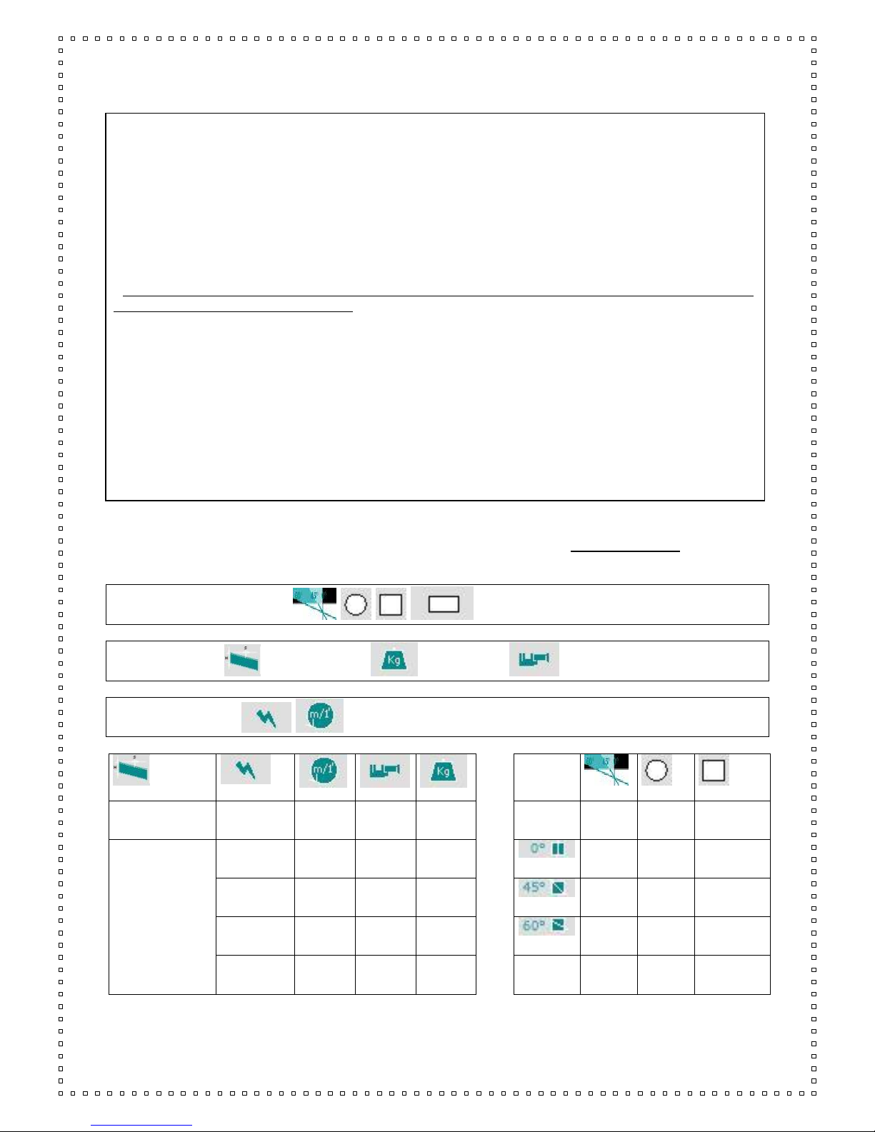
= cutting capacity
= blade size = weight = vice opening
=motor type with related blade speed (at 50 Hz);
mm.
Kw
M/min
mm
Kg
mm
mm
2765x27x0,9
1.5-1,8
3~
35-70
300
412
255
230
300x180
210
190
200x160
1.5
3~
18/110
(ESC)
300
417
135
110
130x100
45° Right
180
160
180x100

INSTRUCTIONS FOR USE
BS300 Plus SH ED.2010 rev.00 9/53
Dimensions
(mm)
B
Width
L
Length
H
Height
H
Worktable height
When working
900
1700
1860
950
Packed
1400
1400
1680
7 –INSTALLATION
This machine can work according to the parameters provided by the manufacturer if correctly installed and if
the minimum requirements are observed, as follows:
- It must be used indoor and with temperatures from +5 to + 40 ° C.
- The relative humidity of the environment must not be over 95%.
- The nominal value of the voltage must be between ± 10% and the frequency must be between ± 2% of the
nominal value.
The floor must have a proper loading capacity and be flat.
Floor space, operator position and working area are indicated in the included drawing that concerns only the
bandsaw, without optional accessories.
The worktable must be levelled by using the screws and nuts put in the little feet holes. The machine has to
be fixed to the floor (it is especially necessary with connected accessories).
The included electrical schemes reproduce the necessary details to arrange the connections, to be
suited for a 4 KW power request.
Earthing of all the electric parts with a dedicated GREEN/YELLOW wire, connected with a TN system
to the supply cable. A supplementary earthing point –indicated with PE –can be located on the
metallic structure of the machine.
At the origin of the power supply cables a device (such as fuses) to protect against overloading has
to be installed. On the models equipped with electronic variable-speed drive unit (ESC), in order to
connect the differential protection on the power supply line, switches with a threshold of interference
on the power dissipation of not less than 300 mA (size 0.3 A or higher is recommended) have to be
employed, having possibly time adjustment availability (0>1.5 sec).
E.M.C. - Electromagnetic noise
The user is responsible for installing and using this saw according to the manufacturer’s guidelines outlined in
this manual. This equipment complies with the protection requirements established by the Directives
2006/42/CE, 2004/108/CE, concerning Electromagnetic Compatibility (EMC). It is in compliance also with the
technical guidelines of the Norms EN 55011, EN 50082-2 and it is intended for industrial and not for
household use.
Before installing the machine the user must take into account possible electromagnetic problems of the
working area. In particular we suggest to install the equipment away from:
- signalling, control and telephone cables;
- radio-television transmitters and receivers;
The supply cable has to be as short as possible, with no twists. All doors, coverings and frame have to be
closed when the saw is running. Do not make any modifications to the machine except for adjustments and
replacements allowed/recommended by the manufacturer. Follow the maintenance schedule.

INSTRUCTIONS FOR USE
BS300 Plus SH ED.2010 rev.00 10/53
8 - MOVING AND SHIPPING
The packing of the machine guarantees protection even during shipments with normal means of transport.
Special packing can be supplied in case of particular requests by the user.
These models are supplied with a carton packing which allows to store them one above the other (1+1 max.)
and to move them for a short way.
After unpacking, remove the locks between base and floor stand, assemble them and place the unit the
working area.
The floor stand is not assembled when delivered, it must be fixed to the machine by means of screws on the
four corners. The rear side is punched. Use two lifting belts, placed below the front and back side of the base
and put the machine on the floor stand. The weight is shown on the packing and also written in the technical
data of the manual.
Make sure that the lifting tools are suited to the weight and that the operation is correctly made without
unbalancing the machine.
In case the bandsaw has to be moved again, fix always the machine to the floor stand.
For the transport of the machine only the methods indicated below are possible. However, be sure that the
means of transport snd lifting are able to stand the machine's weight and its packing (about 500 Kg):
WARNING
The personnel in charge of loading, unloading and moving the machines should use protective gloves.
WARNING
When lifting or moving the machine, or a part of it, take care of clearing the operations area of the people,
considering also an appropriate safety area around it, so as to avoid any risks of injuring people or damaging
things located nearly.
Special packings –wooden crate , wooden case –may be predisposed on request, by charge.
ALL THE OPERATIONS THAT INVOLVE MOVING THE MACHINE MUST BE CONDUCTED WHILE
RESPECTING THE FOLLOWING BASIC RULES:
+ When moving the machine, an appropriate means has to be used, with a loading capacity higher than
the weight to lift, which is indicated on the machine.
+ When choosing and then using equipment such as ropes, chains or lifting belts, be careful about their
geometry during the lifting and about the consequent actual loading capacity.
+ The machine is structured so as to offer lifting points, which are appropriately indicated and will have to
be used for lifting it.
+ In case the lifting belts touch parts of the machine, nylon belts are required; ropes or chains wrapped
with jute or clean covering can also be used. A great care is necessary while slinging and moving the
machine in order to hinder damages.
+ All operations have to be conducted with graduality, so as to avoid jolts and dangerous situations.
+ The person in charge of the operations has to make sure that all the national, local and company norms
in reference to injury prevention and work safety are respected.
+ Onr or more areas for material storage have to be identified.
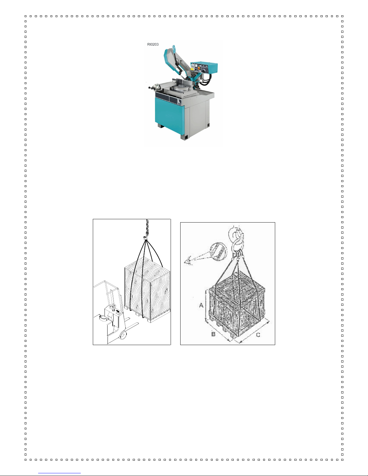
Transport with machine at sight
This type of transport is usually chosen for deliveries by covered truck, in case of short trips. The machine is
wrapped with thermoplastic material in order to assure a suited protection of all its parts; the machine is then
loaded on a truck and should be wrapped with ropes that tie it up . To lift it, use a forklift from front side of
machine, with forks length 1.5 m or more.
Warning: if machine is delivered by open trucks, please cover it !
INSTRUCTIONS FOR USE
BS300 Plus SH ED.2010 rev.00 11/53
Transport with wooden crate or wooden case. ( BY REQUEST , ON CHARGE )
The machine is wrapped with thermoplastic material in order to assure a suited protection of all its parts; then
it is packed into a wooden crate or cage to protect it from collisions, inclement weather and so on.
To lift it, use a forklift from front side of machine, with forks length 1.5 m or more (see picture ).
You need to follow the indications you find on the packing before proceeding to moving or opening it.
WARNING
The size of the packing varies according to the machine ordered and its configuration.
WARNING
The machine is fixed to the packing by means of screws, so as to hinder that it can move during the transport
(see drawing in the following page)
9 - FITTINGS / ACCESSORIES
The necessary information for the installation are given along with the related accessories. Anyway you can
find here short description of several products.
Electronic Inverter for blade speed (ESC) –it can be installed while manufacturing the machine, not later. It
allows to have variable blade speed. The Inverter box is fixed to the floor stand before placing the saw
on it. An handle placed on the control box allows to vary the blade speed, which is shown either in M/Min or
FPM. A green light on the control panel, when off, shows that the maximum power supply threshold has
been exceeded; thus the motor stops. This can happen for a number of reasons: excessive cutting pressure,
unsuited blade speed, and so on.
To start working again, turn off the machine, wait one minute and then turn it on again.
Adjustable Length Stop –standard device: Placed on the right side of the worktable, it is useful when
INSTRUCTIONS FOR USE
BS300 Plus SH ED.2010 rev.00 12/53
making several cuts with the same cutting length.
Loading roller table –To install them correctly, the saw must be fixed to the floor. The machine is equipped
with connection for loading table (left side). Remove the roller to connect the first element of the loading table
(type RTS). To connect the unloading table (right side, type RTS, RTM or RTD), the connection element
RAB2PS is required.
Start aligning the roller tables with the one which is nearest to the saw. In case of long bars, it is
recommended to fix the legs to the floor and recover the coolant left on the bars after the cut. On the
unloading side they can be equipped with a metric rod to check the cutting length (RTM) or with digital
measuring system (RTD). The RTD has to be completed with a device to synchronize the sawframe motion
and the automatic lift of the length stop at the start of the cut.
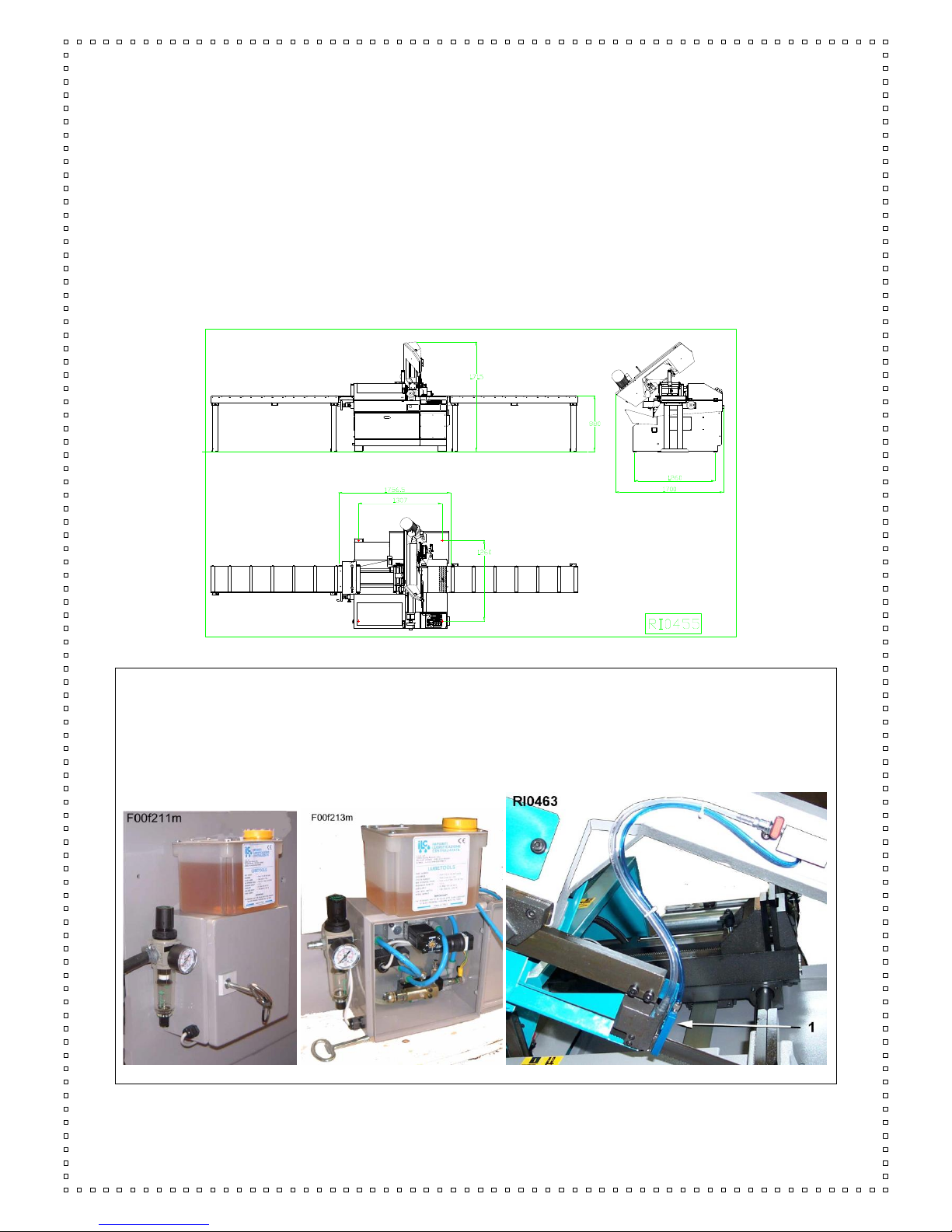
Minimal lubrication system –This device, applied to the saw, allows to eliminate almost completely the
traditional coolant system, keeps the material much cleaner and avoids to waste cutting oil and water. It
works only during the cut.
It is comprised of a nozzle - 1/RI0463 - with 5 micro-holes, a tank with devices to adjust the quantity of oil and
the air pressure. The switch of the electric system - 3/RI0462 - working with low tension 24V AC allows to turn
it off at any moment and use the normal coolant system

INSTRUCTIONS FOR USE
BS300 Plus SH ED.2010 rev.00 13/53
Foot control - supplied as optional. It is connected to the socket placed on the rear part of the panel. By
pushing it, the machine starts.
Supplementary pneumatic vice - connected to the standard vice, allows to lock workpiece on both sides of
the cuts (only for 90 degrees cuts)
Voltage transformer - set it between the electric equipment of the building and the electric supply of the
machine. It allows to work with a different voltage than the standard one (that is 400V / 50 Hz).
Available voltages: 230V, 460V, 500V, 575V.
10 - BAND CHOICE for BS 300 MODELS
In this paragraph we recommend the type of blade according to the material to cut. To get the best
performance from this machine it is necessary to understand how to use the tools and what you do not have
to do with them. The blade for this bandsaw must have the following size (mm) :
maximum length = 2770 minimum length = 2750 height = 27 thickness =0,9
The type of blade is also important, usually it’s a bi-metal blade with different HARDNESS, named M42 or
SVGLB ( for general purpose, tubes, profiles and solids, available in all pitch type), M51 or SHL
(preferred for big solids of hardening steel, INOX material too, available with 3/4 tooth pitch).
The durability of the teeth increases, and also the fragility, when going from the material M42 to M51.
To making a correct cut it’s essential to choose the pitch ( t ) or the number of the teeth per inch (z).
Usually the blade must have a pitch as follows :
- high pitch (small teeth), to cut thin materials, tubular and profiles.
- low pitch (big teeth), to cut solids or particular sections that require at times a big blade effort (for example,
the central part of a U profile), or softer materials as aluminium, copper, soft bronze.
By choosing the right one you can avoid a lot of working errors, get a good cut and the necessary room for
the chips. If you cut more bars at the same time, you must consider them as a single bar and consider
the total size. The following table provide the information for a correct choice, it can also be updated or
modified by the user according to his personal experiences.
Even if blades with constant pitch are available, most bandsaws allow to use blades with variable pitch -
groups of teeth with different pitch between them - which reduce vibrations and noise, improving the quality of
the cut and the performance.
SUGGESTED TOOTH PITCH
SOLIDS
Outside
Diameter
(mm)
BIG
PROFILE
S
Wall
Thickness
(mm)
PROFILES
Wall
Thickness
(mm)
BUNDLE
Length
to Cut
(mm)
VARIABLE
CONSTANT
14 M42
-
-
1,5 max
-
10/14 M42
10 M42
-
-
1 to 2
-
8/12 M42
8 M42
20 max
-
2 to 4
-
6/10 M42
6 M42
40 max
-
4 to 8
-
5/8 or 5/7 M42
5 M42
30 to 80
6 to 12
-
50 to 100
4/6 M42
4 M42
40 to 90
10 to 20
-
70 to 120
3 / 4 M42 or M51
3 M42 or M51
70 to 150
15 to 40
-
100 to 200
2/3 M42 or M51
2 M42 or M51
120 to
230
over 40
-
120 to280

INSTRUCTIONS FOR USE
BS300 Plus SH ED.2010 rev.00 14/53
The following chart refers to the cut of a solid with diameter 80mm, using a standard bandsaw.
If the material size changes, the corresponding parameters change as well, according to the type of
machine and to the possible accessories which have been installed. For example, in case the material size
increases, these parameters have to be reduced, and vice versa.
Using manually a saw often means a significant variation of the cutting times, because of the inconsistent
down-feed speed.
MATERIAL
GROUP
i.e. DIN
denomination
DIN N°
Maximum
BLADE
SPEED
m/min
Minimum
BLADE
SPEED
m/min
MOTOR
SPEED
(1or2)
FEED
FORCE
COOL
ratio
1)STRUCTURAL
STEEL
St37 St42
10037-10042
60
40
1.
LOW
10%.
St50 St60
10050-10060
50
35
1
LOW
10%
HARDENING
STEEL
C10 C15
10301 10401
45
35
1
LOW
15%
16MnCr5 20CrMo5
17131
17264
40
30
1
Low/Me
d
10%
AUTOMATIC
STEEL
9S20 10SPb28
10711
70
50
1 2
LOW
15%
BEARING STEEL
100Cr6
13505
40
25
1
Med/Hig
5%
SPRING
STEEL
65Si7
15028
40
30
1
Med/Hig
5%
2)TOOL STEEL
UNALLOYED
C80W1
C125W
11525
11663
40
30
(1)
HIGH
5%
ALLOYED
210Cr12 X155CrVMo
12080 12379
30
20
(1)
HIGH
dry
X40CrMoV51
12344
35
20
(1)
HIGH
5%
HIGH SPEED
STEEL
S-6-5-2-2
13243
30
20
(1)
HIGH
5%
INOX STEEL
X5CrNi18 X10Cr1810
14305
30
20
(1)
HIGH
5%
3)SPECIAL
ALLOYS
NiCr19NbMo
(Inconel)
24668
20
15
--
HIGH
20%
NiMo30
(Hastelloy)
24810
20
15
--
HIGH
15%
NiCr13Mo6Ti3
(Nimonic)
24662
20
15
--
HIGH
15%
TITANIUM
Ti1
37025
30
20
(1)
HIGH
10%
G-TiAl6V4
37164
35
20
(1)
HIGH
10%
4)CAST IRON
GG15 GG30
--
50
30
1
Med/Lo
w
dry
5)NOT-FERROUS
ALUMINIUM
AL99.5 GalSi15Mg
--
300
50
2
Med/Lo
w
2%
BRONZE
CuSn6 CuSn6Zn
--
120
40
2 1
Med/Hig
2%
COPPER
G.Cu Ke.Cu
--
200
50
2
LOW
2%

INSTRUCTIONS FOR USE
BS300 Plus SH ED.2010 rev.00 15/53
11 - INSTRUCTIONS FOR USE AND WARNINGS
This machine can make automatic work cycles, however at the end of each one the operator has to remove
the material that has been cut and possibly change the cutting conditions. Therefore the saw sometimes
must be manually adjusted and then it works in automatic cycle (so the operator is not indispensable).
The working cycle ends when the machine stops; in order to begin a new cycle, the starting procedure will
have to be repeated.
11.1 - This machine is designed and manufactured so as to be safely used by the operator, provided
that it is properly run. No protections will ever suffice if the operator does not work with caution, does not
make sure that the machine is in top working conditions and does not follow the instructions below.
Don’t forget that this bandsaw is designed to CUT METALS with a proper tool, and that you are responsible
for a SAFE and CORRECT use. You must :
1. check that the machine is properly installed and electric supply is suited.
2. be sure to learn all main features of the saw before running it.
3. do not expose yourself or any other people to any risk.
4. wear personal protective equipment
5. do not remove or modify the SAFETY DEVICES installed by the manufacturer, make sure that they are
always in a good condition, too.
6. follow a regular maintenance schedule and check regularly the efficiency of the saw.
7. never use tools with unsuited characteristics
8. do not try to cut material with a size bigger than the cutting capacity of the machine
9. Keep the cutting area clear of tools or other loose objects.
10. do not run the saw unless all guards and protections are in place
11. NEVER WEAR loose clothing, long sleeves, large gloves, jewellery, or any other items that may get
entrapped into the machine
12. Always disconnect the power supply when performing maintenance or making adjustments.
13. do not get close to the cutting area with your hands or any other part of your body when the saw is
running
14. Clamp properly the material in the vice and never hold it with your hands
15. Support appropriately the bar from both sides to prevent it from falling
We recommend to install a roller table on the unloading side in case the cutting length of the bar is bigger
than the distance between the blade and the right side of the basement
16. When cutting very short pieces, make sure they do not jam into the blade.
17. If the blade remains entangled with the material, stop the machine, open the vice and remove the
material, then check the condition of the blade and the teeth: if they are damaged or broken, change the
blade
18. Apply a constant pressure during the cut
19. Do not move the saw during the cut or cause instability
20. Wear personal safety equipment when running the machine
ALWAYS RUN THE SAW SAFELY, USING COMMON SENSE AND ALERTNESS

INSTRUCTIONS FOR USE
BS300 Plus SH ED.2010 rev.00 16/53
On some parts of the machine there are some stickers which warn about the safety measures that have to be
taken by the operator who runs it. Their meaning (easy to understand) is indicated in the following chart
INSTRUCTIONS FOR USE
BS300 Plus SH ED.2010 rev.00 17/53
11.2 - OPERATOR’S SAFETY
This section illustrates the safety protections applied on the saw, according to the current legislation in the
field of safety.
11.2.1. ELECTRIC EQUIPMENT –norm EN 60204-01
. . Electric board closed with screws - general switch
. Marking of the electric components used, according to the indications on the electric scheme
. Control circuit with 24V tension –Control transformer with fuses on input and output
. Earthing of all electric parts with a dedicated GREEN/YELLOW wire, connected with a TN system to the
supply cable. A supplementary earthing point –indicated with PE –can be located on the metallic structure of
the machine.
. Minimum tension coil that prevents accidental restarting after a lack of tension.
. Protection from overloads and high temperature thanks to bimetal thermo-protectors placed directly in the
blade motor
. Emergency button for interrupting immediately all the movements of the machine. In order to restore all the
functions, rotate the button half a turn.
. Sensor of the blade tension: in case the blade breaks or the tension strength diminishes, the machine stops
immediately
. Sensor of the closing of the blade protection: if it opens during the working, the machine stops..
. The stop caused by one of the aforementioned devices needs a complete restoring of the working cycle
11.2.2 –PROTECTION AGAINS ACCIDENTAL CONTACTS
. . Complete metallic protection of the blade and the pulleys, the blade-cleaning brush and the back blade-
driving pads
. Forward metallic moving guard, fixed to the forward blade-driving pad. It assures the coverage of the blade
in every position, except for the stretch of blade which makes the cut. Joint to the blade-driving pad, it can be
opened only after the opening of the main protection
. Self-positioning of the saw blade, in order to limit the width of the danger area to the stretch of blade strictly
necessary for the cut.
. During the cycle an automatic approaching device stops the saw blade near the material, in order to start
the cut.
. Clamping vice with a maximum stroke of 7 mm, according to the norms on automatic closing
. Guard extended to both sides which retains the coolant used during the cut, preventing its spilling on the
floor
. Parts of the machine with suitably chamfered or rounded angles
11.2.5. LIGHTING OF THE WORKING AREA
An inappropriate lighting can cause accidents to the operator, who consequently needs a suited lighting in the
working area. In case of a lack of precise indications (for example, norm ISO 8995) for special areas, we
recommend to supply a lighting equal to 750 LUX.
INSTRUCTIONS FOR USE
BS300 Plus SH ED.2010 rev.00 18/53
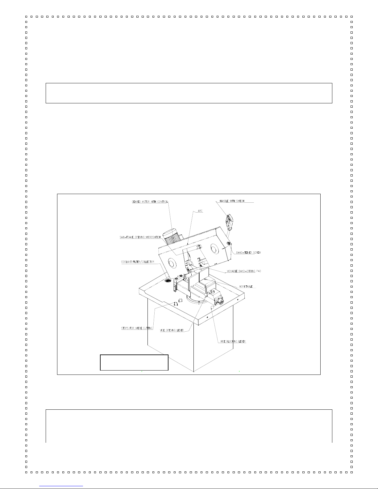
12 - MACHINE DESCRIPTION, E.C. SAFETY NORMS, PROPER USE
Bandsaw for mitre cutting from 45° right to 60° left of metal profiles and solids. The SH model allows to
perform semiautomatic cuts (without air supply is possible to use it as a manual machine). The
emergency RED/YELLOW switch allows to stop the saw at any time, especially when performing automatic
cuts.
It is not suited to cut wood and assimilated materials (see D.M. 2006/42/CE, enclosure I,
paragraph 2.3)
As a manual machine, the following operations have to be done manually: material clamping, sawframe drop
and cut, sawframe return, material unclamping and feeding for a new cut.
The blade start is controlled by the button inside the handle, which has a safety guard to prevent unintentional
starts.
The Machine Directives and the Norms applied when designing and manufacturing this bandsaw are
mentioned in the enclosed Declaration of Conformity.
From the working position, in front of the vice, the operator has the possibility to activate all drivers and check
the correct working of the machine, as well as to avoid risky areas.
In the following paragraphs you will find all information to use the machine in the best way and for a very long
time.
The choice and the use of the parts have been made by considering the conditions of use and the long
machine life.
1.1 - APPENDIX FOR E.M.C.
The structure of this machine is complying to the protection requirements of the EEC Directives 89/336/EEC,
92/31/EEC and 93/68/EEC in terms of Electromagnetic Compatibility (E.M.C.).
BS 300 PLUS SH

INSTRUCTIONS FOR USE
BS300 Plus SH ED.2010 rev.00 19/53
In particular it respects the technical prescriptions of the norms EN 55011 and EN 50082-2, and it is foreseen
to be used in industrial enviroments and not in residential ones.
13 - MACHINE SETTING FOR STARTING
Verify that the machine has not apparent damages or faults and check the standard equipment that includes
tools, fittings to carry out some adjustments, use and maintenance handbook. In case the machine is
supplied with additional equipment make sure that it is suited to the machine. Inform promptly the Imet dealer
about damages or faults before starting to work with the machine. Remove the locking shaft between
sawframe and base, fix in the handle-holder the plastic screw for band guide fixing –4/RI0461-.
The protective substances put on the surface to protect the saw during the transport must be cleaned by
means of a cloth or paper, please check that there is no rust on the metallic parts as well.
In case compressed air jets are used, always wear proper eye protection.
The parts in motion (band guides, trolleys, pivots, bearings, and so on) have already been lubricated, the
reducer contains the exact oil quantity necessary to work.
The pneumatic installation is ready to start.
COOLING SYSTEM
Prepare the cooling by mixing the cutting oil and water ( the tank holds about 12 litres ) in proportion of 1/10,
1/15 or according to the instructions of the supplier of the product. Lift the punched lid of the tank and pour
out some cooling in the tank or directly on the work table-pos.1/dr.RI0074.. In this case keep attention that
cooling does not come out of the holes placed on the two sides of the floor stand, near to the electropump.
PNEUMATIC CONNECTION
The machine is fitted out with the filter-reducer-lubricating unit for the air-dr.RI0340, but it is right to connect it
to a system provided at least with condensate discharger, with pipes correctly setted, at least with a pressure
of 7/8 BAR . The consumption of the air is about NL ..6. for each automatic cycle.
ELECTRICAL CONNECTION
Verify that the voltage and the power frequency are compatible with numbers reported in the technical data
plate ( it is placed on the right side of the floor stand ) a difference over 10 % causes some working
unevenness more or less manifested. Connect the switch to a suitable socket or replace it with that of normal
use. The phasing performed by the manufacturer allows to get a rotation of all motors by connecting the
wires in the following order L1=R, L2=S, L3=T, anyhow check as follows :( close the carter in the tight way,
connected air, pressure > 2 bar ).
a) in case of EMERGENCY, the button is on, turn it off and turn it 1/4 of turning in the marked direction.-
pos.2/dr.RI0077-.
b) turn "ON" the main switch-pos.1/dr.RI0077-, the line warning light -pos.6/dr.RI0077-of the close band
carter-pos.10/dr.RI0077, and the warning light of band tension -pos.9/dr.RI0077- mush flash.
c) choose the motor speed by pushing the button 1 or 2.-pos.3/dr.RI0077.
d) turn the cutting speed commutator on "0"-pos.8/dr.RI0077.
e) push the white button START-pos.6/dr.RI0077- of starting cycle
f) check that blade moves; the direction indicated by the ARROW PRINTED -pos.2/dr.RI0074 - on the carter
shows the right movement.
g) if not , it is necessary to tension the band according to the instructions of the following paragraph.

INSTRUCTIONS FOR USE
BS300 Plus SH ED.2010 rev.00 20/53
h) after this, repeat again form point a) check that blade moves in the right sense and if not, after turning the
general switch on "OFF" disconnect the feeding plug, reverse the connection of the both line connection wire,
excluding green/yellow cable of grounding and star again from point a).
Be sure that coolant is sucked in by the tank and it arrives in the cutting area.
i) stop the working by pushing the general switch-pos.1/dr.RI0077.
14 - BAND TENSION
This saw is equipped with a blade which is already tensioned, so as to allow the motor to start (the
saw doesn’t work if the blade does not have the correct tension).
It is recommended to verify, while the machine is off, that the blade is correctly placed: open the blade guard
and fix it with the back hook - 1/RI0456 –then make sure the blade is about 1-2 mm away from the edge of
the pulleys –2/RI0456 –and correctly placed in the guides –3/RI0456. if necessary, loosen the blade-
tensioning screw - 4/RI0456 –to be able to change the placement of the blade, then assemble the blade
guard again. Be sure that the end-stroke key is suitably placed into its location - 5/RI0456
With the compressed air connected, after turning on the main switch-pos.1/RI0077, the led light of band
tension -pos,9/dr.RI0077- unflashing means that the band must be tensioned.
It is necessary to screw the front screw-pos.4/dr.RI0461- by using the hexagonal spanner until the led will
be continuingly flashing; tighten for 1/4 of a round more to prevent future loosening.
Table of contents
Other IMET Spa Saw manuals


Popular Saw manuals by other brands


Makita
Makita JR3050T instruction manual

MK Diamond Products
MK Diamond Products MK CX-3 Owner's manual & operating instructions

Sealey
Sealey TS1098 instructions

Craftsman
Craftsman 315.212120 owner's manual

Parkside
Parkside PFS 710 D3 Translation of the original instructions

DeWalt
DeWalt DWS713 Original instructions

Holzmann
Holzmann KAP 305ECO user manual

MK Diamond Products
MK Diamond Products HD-101R Owner's manual operating instruction & parts list

DeWalt
DeWalt DWE7485 Original instructions

MK Diamond Products
MK Diamond Products MK-660 SERIES Owner's manual & operating instructions

Black & Decker
Black & Decker 7578 owner's manual

Evotools
Evotools COS 2300 EPTO user manual