IMI BUSCHJOST 82590G Series User manual
1
11/2018 1377006.0000.10011
Operation manual –
pre-controlled diaphragm valves
with forced lifting
Document No. 1377006.0000.10011 Revision 8
Translation of the original operating manual
Status as of November 2018
1 About this documentation
These mounting instructions guides you to
mount, operate and maintain pre-controlled
diaphragm valves with forced lifting safely.
This operation manual is intended for:
plant operators, installers, maintenance and
service technicians.
1.1 Documentation validity
This operation manual applies to the following
series
•82540, 82590 (G-Thread)
•82640, 84490 (NPT-Thread)
•for special products that are based on the
series mentioned above
in combination with these solenoid:
Series 9151
9154
9176 x
9191 x
9301
9304
9356 x
9326 x
9401
9404
82540 G •••
82590 G • •
82640 N •••
84490 N • •
Order No. Connection Connection
xxxx0xx G 1/4 1/4 NPT
xxxx1xx G 3/8 3/8 NPT
xxxx2xx G 1/2 1/2 NPT
xxxx3xx G 3/4 3/4 NPT
xxxx4xx G 1 1 NPT
xxxx5xx G 1 1/4 1 1/4 NPT
xxxx6xx G 1 1/2 1 1/2 NPT
xxxx7xx G 2 2 NPT
Series 82540,
82590
82640,
84490
1.2 Structure of safety instructions
Safety instructions warns against dangerous
situations and must be observed in particular.
Safety instructions are structured as follows:
SIGNAL WORD
Type of hazard
Consequences of non-observance
→Precautions necessary to avoid the hazard
1.3 Hazard classes (ANSI Z535.6)
!DANGER
Safety information indicates a hazardous situation
with high risk which, if not avoided, will certainly
result in death or (serious) injury.
!WARNING
Safety information indicates a hazardous situation
with moderate risk which, if not avoided, can cause
death or severe injury.
!CAUTION
Safety information indicates a hazardous situati-
on which, if not avoided, could result in minor or
moderate injury.
NOTICE
Information indicates a hazardous situation which,
if not avoided, could result damage to property.
Keep documentation for future use!
Contents
1 About this documentation 1
1.1 Documentation validity 1
1.2 Structure of safety instructions 1
1.3 Hazard classes (ANSI Z535.6) 1
1.4 Styles and symbols 2
1.5 Intended use 2
1.6 Improper use 2
1.7 Obligations of operator 2
1.8 Personnel qualification 2
1.9 Personal protection equipment 2
2 General safety instructions 2
3 Avoid damage to property 3
4 Identifying the valve 3
5 Transport and storage 3
6 Function 3
6.1 NC-valve (normally closed) 4
6.2 NO-valve (normally open) 4
6.3 Solenoid types AC/DC 4
7 Mounting 4
7.1 Valve dimensions in mm 5
7.2 Mounting accessories 5
7.3 Conditions of installation 5
7.4 Preparation 5
7.5 Mounting valve to pipeline 5
8 Connecting solenoid electrically 6
9 Operating conditions 7
10 Commissioning 7
10.1 Checking the switching function 7
10.2 Flooding the valve 7
11 Operation 7
12 Maintenance 7
12.1 Cleaning and visual inspection 7
12.2 Checking for tightness and strength 7
12.3 Preparing maintenance of internal parts 7
12.4 Checking valve parts 8
12.5 Cleaning valve parts and valve 8
12.6 Replacing spare parts 8
12.7 Tightening torque screws 8
12.8 Lubricating valve parts accordingly 8
12.9 Valve-specific disassembly/reassembly 8
13 Re-commissioning 14
14 Decommissioning 14
15 Replace complete valve 14
16 Trouble shooting 14
17 Return 14
18 Disposal 14
19 Directives and certificates 14
B1
82640 N
84490 N GG-Thread
NNPT-Thread
Series
82540 G
82590 G
2
11/2018 1377006.0000.10011
1.4 Styles and symbols
This documentation uses the following styles
and symbols:
• List
→Instruction
1.
2.
Preset order of instructions
701 Part number (according to part list)
1 Flexible part number (section)
qReplace spare part
!+ DANGER /WARNING /CAUTION;
NOTICE: embedded safety message
given limits or fixed value
1.5 Intended use
The valve is solely intended to control or stop
a fluid flow within approved operating limits.
The fluid must only flow through the valve in
the determined flow direction.
You may only operate the valve with fluids that
will not cause any chemical reaction with the
valve’ materials or lead to abrasive effects.
Under the following conditions, a valve with
nominal diameter > DN 25 is not approved as
the only shut-off valve at the end of a pressure
line:
•The contents of the pressure system must
not be released into the atmosphere.
•The contents of the pressure system must
not be transferred to a downstream system
with lower nominal pressure rating (PN).
1.6 Improper use
In the following cases it is prohibited to opera-
te the valve:
•The valve is not used for the designated
purpose.
•The permitted temperature and pressure
ranges are exceeded.
•Damages to the valve – e.g. cracks,
deformation – were detected but the valve
remains in operation.
•Malfunctions were detected but the valve
remains in operation.
•The valve has been modified without authori-
zation of the manufacturer.
•The safety instructions of this documentation
are not observed.
For damages caused by improper use, the
liability of the manufacturer is excluded.
Our guarantee expires in the
following cases:
•Undue intervention and altering are done to
the valve.
•This documentation or the operating limits
as shown in the particular datas heet are not
observed.
1.7 Obligations of operator
Product
→Over the entire life cycle of the valve all
applicable regulations must be observed.
The instructions of this operation manual
must be observed and followed.
→Initiate a risk assessment of the overall
installation, to detect potential dangers that
may occur in combination of the valve with
other components.
Persons
→Initiate the instruction of each person who
is working with the valve.
Applicable regulations about occupatio-
nal safety ad safety engineering must be
known and applied.
Documentation
→This documentation must be fully read and
understood.
→The instructions given in this operation
manual must be put into practice.
→This documentation must be available at
any time.
Markings at the operating site
→Ensure adequate warning of the risks linked
to the valve. Use in the area of the installed
valve the following warning and prohibition
sings in compliance with EN ISO 7010 und
BGV A8 (VBG125):
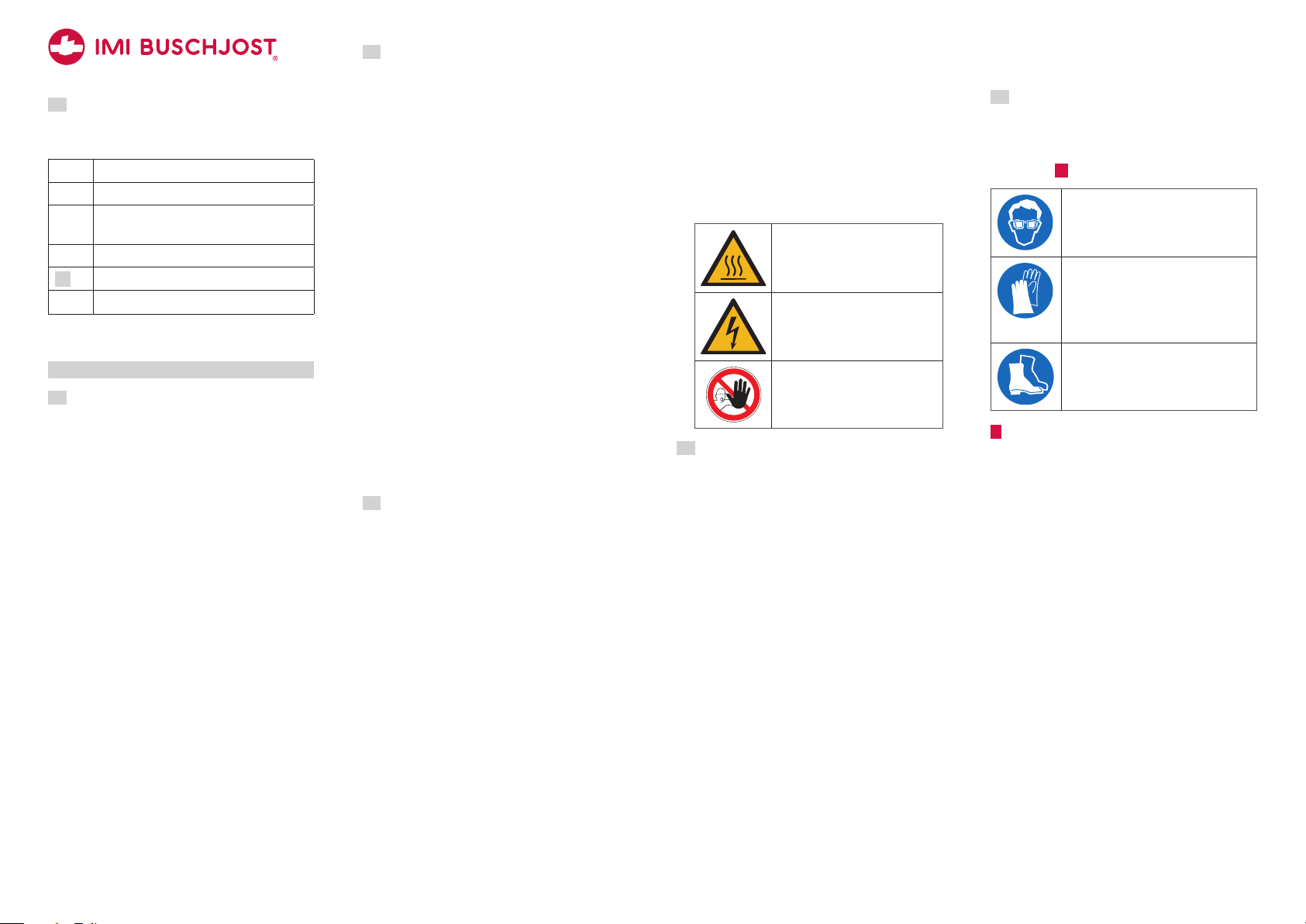
Warning sign to indicate risk of
burns at the solenoid
Warning sign to indicate elec-
trical hazards at the solenoid
Prohibition sign to
prevent people from entering
hazardous areas
1.8 Personnel qualification
→Ensure as operator that persons who work
on or with the valve are sufficient qualified
for this job.
→Comprehensively train the operating per-
sonnel in terms of safety.
→Only allow trained specialists to perform
electric connections, commissioning, main-
tenance and trouble shooting
Demands
Operating personnel must be instructed on
operational sequences and procedures.
Operating personnel must know its responsi-
bilities regarding the work to be performed.
Trained specialists must possess profound
knowledge in mechanical engineering, electri-
cal engineering, hydraulic und pneumatic.
Trained specialists must be authorized to
commission, ground and designate devices,
systems and power circuits according to the
standards of safety technology.
Trained specialists must possess profound
knowledge about design and principle of ope-
ration of the valves and the plant.
1.9 Personal protection equipment
→Wear appropriate protection equipment.
Observe the personal protection equip-
ment as requested in “residual risks” (see
chapter 2 ).
Protective eye glasses
to protect from escaping fluids or
exhausting compressed air
Protective gloves
resistance to cutting to protect
from sharp edges or ridges;
resistance to acids to protect from
hazardous fluids
Protective footwear
to protect from parts or tools falling
down
2 General safety instructions
These safety instructions are only related to
the single valve. In combination with other
plant components there may be other potential
dangers, which must be taken into account by
carrying out a risk analysis for the system.
→Compare the details on rating plate and
data sheet to the operating data. The limits
for the particular application (e.g. pressure,
temperature) must not be exceeded.
→Only perform assembly and maintenance
works when the pipe system is in depres-
surized state.
→Flood the valve slowly during commissio-
ning. Fast pressurizing will cause the valve
to open briefly.
→Strength tests with the valve seat open are
permitted maximum up to 1.5 times of the
nominal pressure rating (PN) at room tem-
perature. The valve must not be operated
during these tests.
B1

3
11/2018 1377006.0000.10011
!DANGER
Hazardous electrical voltage
(>25V AC; >60V DC)
There are risks from electrical
voltage during assembly and
maintenance.
→The electrical connection of the solenoid
must be carried out only by a qualified
electrician.
→You may only plug or remove the device
socket in de-energized state.
→Disconnect the power supply off the sole-
noid prior to assembly or disassembly.
!WARNING
Danger from pressurized
pipelines
Pressurized pipelines may burst
resulting in injuries.
→Depressurize pipe system and block the
fluid flow prior to opening or unmounting
the valve.
!CAUTION
Risk of burns at the solenoid
Solenoid is heating up during
operation. Touching the solenoid
leads to risk of burns.
→Let the solenoid to cool down before
working on the valve.
Residual risks
kg
Weight of the valve
Phases: transport, storage,
assembly, maintenance, disposal
Risk: falling off, tipping over
Personal protection equipment
(PPE): Protective footwear
Hazardous fluids
Phases: assembly, operation,
maintenance, disposal
Risk: skin contact, eye contact,
breathing vapors
PPE: protective gloves, protective eye
glasses, breathing protection
Potentially explosive atmosphere
Risk: danger of explosion
!WARNING: use solenoid an de-
vice socket with Ex-protection.
Sharp-edges and threads
Phases: transport, assembly,
maintenance, disposal
Risk: risk of cuts
PPE: protective gloves
3 Avoid damage to property
NOTICE
Deposits and dirt lead to malfunctions
If the control bores are clogged or the
core is blocked by soil the valve no longer
closes or opens.
→Install a strainer (mesh size ≤0.25mm) in
front of the valve inlet P if necessary.
Damages through accumulation of heat
The solenoid will overheat during conti-
nuous duty if the heat can not be radia-
ted. This shortens the service life of the
solenoid.
→You must not cover the solenoid with paint.
→You must not encase the solenoid in
atight housing or in a thermal insulation.
Residual risks
Pressure against valve outlet
The valve only firmly closes in flow
direction.
Fluid freezing
The valve is not designed to with-
stand the fluid freezing.
4 Identifying the valve
The rating plate is situated on the solenoid
body.
use -plug only
18VA/18W
0–10
XXXX
24 00
8254000.9151.02400
100%
Part no./Bestell-Nr.
VHz
PA bar
D-32545 Bad Oeynhausen
www.imi-precision.com
Buschjost GmbH
Made in Germany
6
2
3
7 *
1
5
4
8
Rating plate (example)
1 Order number
2 Operating voltage
3 Frequency of voltage
4 Power consumption inrush/holding
5 Operating pressure range
6 Date of manufacture (week/year)
7 * if this marking is shown on the rating plate:
use device socket with rectifier
8 Duty cycle
An additional marking is applied to the spring
clip of the c-solenoid 9151, 9154, 9176
and 9191.
G 1/4
0 - 10 bar DC only
8254000.9150
xxxx
xxxx 4
23
22
1
6
5
Marking of the spring clip (example)
1 Order number (without voltage/frequency)
2 Operating pressure range
3 Size of connection
4 DC only (only with DC coils)
5 Date of manufacture (week/year)
6 Serial number
5 Transport and storage
NOTICE
Damage of the valve
Valve may be damaged if foreign particles
get into the valve.
→Transport and store the valve dry and only
in the delivery packaging.
→Take valve out of the packaging immedia-
tely prior to assembly.
→Let the blanking plugs into valve connec-
tions.
Prolonged storage at −10 °C to +20 °C
Avoid during transport:
Mechanical loads: falling off, tipping over
Damages to the electrical terminal elements
Avoid during storage:
Thermal stress: permanently increased storage
temperatures; distance to heat sources < 1m
Chemical load: at the storing site through sol-
vents, chemicals, acids, fuels and similar
Weather conditions: at construction sites strong,
watertight containers are necessary
Unfavourable storing conditions may reduce
the service life of the sealing materials
6 Function
Design
2/2-way seat valve with diaphragm as sealing
device.
Operation
The valve is electromagnetic indirectly-control-
led with forced lifting.
B1
4
11/2018 1377006.0000.10011
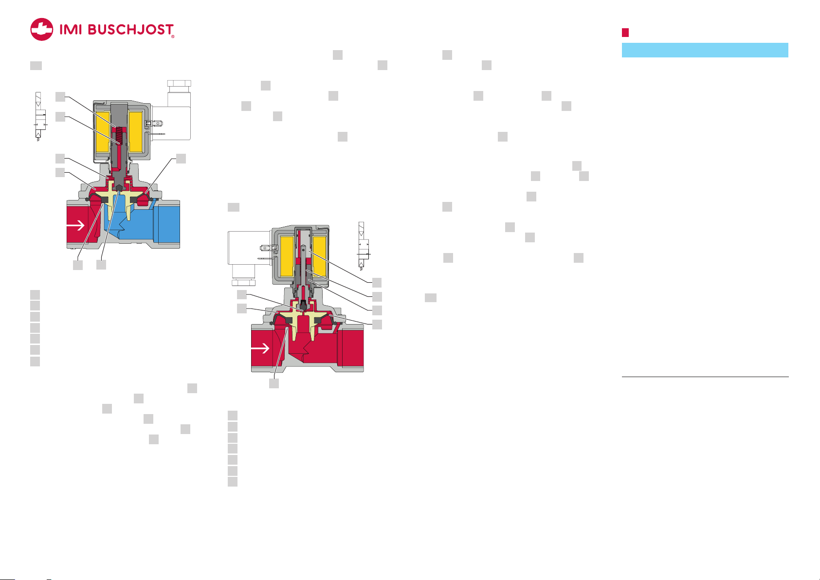
6.1 NC-valve (normally closed)
A
P
PA
6
7
1
4
3
2
5
Sectional view (NC-valve; closed)
1 Main valve seat
2 Control bore in the diaphragm (pressure build-up)
3 Chamber
4 Compression spring above the diaphragm
5 Pilot seat (pressure reduction)
6 Compression spring inside the core
7 Magnet face of the core tube
Normal position: closed
Due to the effect of the compression spring 6
inside the core the pilot seat 5 is closed. A
compression spring 4 presses the diaphragm
sealingly to the main valve seat 1 . The ope-
rating fluid flows through the control bore 2
in the diaphragm to the chamber 3 above the
diaphragm and increases the closing force.
Switching position: open
The magnetic force lifts the core towards
the magnet face of core tube 7 when the
solenoid is energized. Since the pilot seat 5
is open the fluid pressure is reducing from
chamber 3 towards valve outlet. More fluid is
flowing off via the pilot seat 5 to the cham-
ber 3 than the amount flowing in via the
control bore 2 in the diaphragm. The
differential pressure lifts up the diaphragm
and opens the main valve seat 1. Through
the mechanical coupling with the core, the
diaphragm is lifted into open position.
In the absence of differential pressure only
the solenoid force moves the diaphragm in the
open position.
6.2 NO-valve (normally open)
A
P
1
4
3
2
6
5
7
PA
Sectional view (NO-valve; open)
1 Main valve seat
2 Control bore in the diaphragm (pressure build-up)
3 Chamber
4 Pilot seat (pressure reduction)
5 Pole piece
6 Compression spring inside pole piece
7 Core
Normal position: open
When the solenoid is de-energized, the pilot
seat 4 is opened by the effect of the com-
pression spring 6. Through die mechanical
coupling with the core, the diaphragm is lifted
into open position. More fluid is flowing off via
the pilot seat 4 to the chamber 3 than the
amount flowing in via the control bore 2 in
the diaphragm. The resulting differential pres-
sure supports the opening movement.
The main valve seat 1 is open.
Switching position: closed
When the solenoid is energized, the core 7
is attracted by the pole piece 5. The core 7
presses the seal plug sealingly against the
force of compression spring 6 on the pilot
seat 4. Through the mechanical coupling
with the core, presses the diaphragm sealingly
to the main valve seat 1. The outflow of the
fluid flow from the chamber 3 is interrupted.
The operating fluid flows through the control
bore 2 in the diaphragm to the chamber 3
above the diaphragm and increases the closing
force.
6.3 Solenoid types AC/DC
The valve may be equipped without changing
of the mechanical part with an DC voltage
solenoid or AC voltage solenoid. In both cases
the permissible voltage tolerance amounts to
±10%. Special versions may cause deviations.
7 Mounting
NOTICE
Damage of the valve
The valve may be damaged through in-
appropriate installation.
→Only trained and authorized specialists
may install the valve..
→Only use appropriate tools and suitable
sealing materials.
→Make sure that the valve is mounted in
flow direction.
→Make sure not to distort the valve body,
particularly in case of a misaligned pipe-
work.
There must be no mechanical loads ap-
plied to the solenoid.
→Do not use solenoid as a lever during
mounting.
Valve only firmly closes in flow direction.
Inflow against the valve’s flow direction
may lead to the destruction of compo-
nents.
→Implement adequate measures if back flow
is to expect; for example by adding check
valves to the pipe system.
The valve subassembly may get damaged
by external loads at the operating site.
→Protect valve from objects falling down.
→Secure the valve against direct weather
influences and the possible effects.
B1

5
11/2018 1377006.0000.10011
7.1 Valve dimensions in mm
Lø A
H
with solenoid 9151, 9154, 9176, 9191
Connection size L H ø A
G 1/4 1/4 NPT 60 107 44
G 3/8 3/8 NPT 60 107 44
G 1/2 1/2 NPT 67 108 44
G 3/4 3/4 NPT 80 115 50
G 1 1 NPT 95 124 62
Lø A
H
with solenoid 9301, 9304, 9356, 9326 / NC
Connection size L H ø A
G 1/4 1/4 NPT 60 108 44
G 3/8 3/8 NPT 60 108 44
G 1/2 1/2 NPT 67 110 44
G 3/4 3/4 NPT 80 117 50
G 1 1 NPT 95 126 62
Lø A
H
with solenoid 9301, 9304, 9356 and 9326 / NO
Connection size L H ø A
G 1/4 1/4 NPT 60 109 44
G 3/8 3/8 NPT 60 109 44
G 1/2 1/2 NPT 67 111 44
G 3/4 3/4 NPT 80 118 50
G 1 1 NPT 95 127 62
ø A
L
H
with solenoid 9401 and 9404
Connection size L H ø A
G 1 1/4 1 1/4 NPT 132 186 92
G 1 1/2 1 1/2 NPT 132 186 92
G 2 2 NPT 160 200 109
7.2 Mounting accessories
Mounting bracket
With an optional mounting bracket, you can
connect the valve to an load-bearing structure
at the installation site, thus protecting against
vibration, for example.
→Attach the mounting bracket to a long site
of valve cover before to assembly. Use the
fixing screws delivered with the mounting
bracket to achieve the necessary screw-in
depth.
Nm
Mounting bracket (example)
Available mounting brackets
Order No. Connection size
1258986 G 1/4 1/4 NPT
G 3/8 3/8 NPT
G 1/2 1/2 NPT
1258991 G 3/4 3/4 NPT
1258996 G 1 1 NPT
1259005 G 1 1/4 1 1/4 NPT
G 1 1/2 1 1/2 NPT
7.3 Conditions of installation
Compliance with operating limits
Ensure to comply with the operating limits pri-
or to mounting the valve. Observe the valve’s
data sheet.
Planning of the pipe system
The manufacturer recommends to include ma-
nual stop valves and drain valves in the plant
so that the pipe system may be depressurized
and drained prior to working on the valve.
Valve’s mounting position
Valve’s mounting position may be any.
preferably: Solenoid vertical on top
✔✔✔✔
7.4 Preparation
→Check the valve for externally visible
damages.
→Let the valve in its protective package prior
to mounting.
→Make sure that there is enough free space
for disassembly the valve in case of main-
tenance.
→!WARNING Depressurize the pipe
system.
→NOTICE Clean the pipe system prior to
mounting the valve.
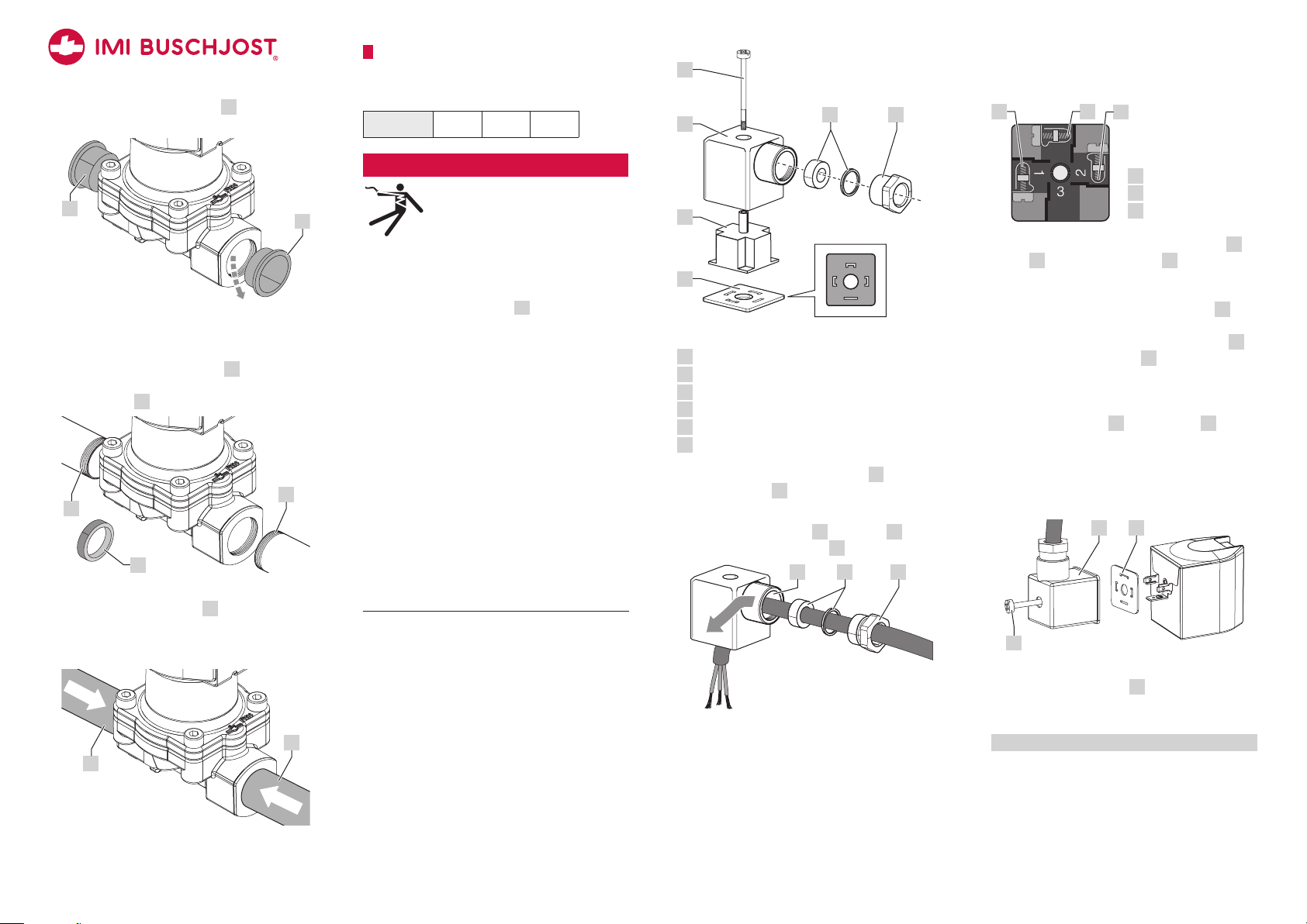
7.5 Mounting valve to pipeline
→Mount the valve to the designated pipeline.
Comply with existing connections.
→Arrange the valve according to the pipe-
line’s flow direction.
An arrow on the valve body
marks the flow direction.
B1
P
A
6
11/2018 1377006.0000.10011
1. Take out the blanking plugs 1 from valve
inlet and valve outlet.
1
1
Take out blanking plugs
2. Install a strainer in front of the valve inlet P
if necessary.
3.Firmly seal pipeline’s thread 2 with an
appropriate sealing material (e.g. PTFE
sealing tape 3).
2
2
3
P
Firmly seal pipeline’s thread
4. Attach pipelines threads 2 to the valve’s
connection threads.
NOTICE Make sure not to distort the valve
body.
2
2
Attach pipelines to valve
8 Connecting solenoid electrically
→Always connect the device socket which
was delivered by Buschjost.
solenoid 915x 930x 940x
!DANGER
Hazardous electrical voltage
(>25V AC; >60V DC)
There are high risks from elec-
trical voltage during assembly
works.
→Work on electrical installations may only
be carried out by a qualified and authori-
zed electrician (refer to 1.8).
→You must connect the earth wire to the
terminal marked with the grounding
symbol y.
→You may only plug the device socket in
de-energized state.
→Make sure that the insulation of the
strands is not pinched.
Connection errors lead to dangers
→After connecting the solenoid carefully
close the terminal compartment to restore
protection.
→To secure IP65 protection after connec-
ting: Carefully close the device socket.
Check whether the flat seal between
solenoid and device socket is properly
seated. Check whether cable gland is
properly sealed.
→Connect solenoid in accordance with the
electrical regulations.
→Use a round cable with diameters from 5
mm to 10 mm. The wire cross section must
not exceed 1.5 mm2.
6
5
4
3
1
2
Overview: Device socket
1 Pressure screw
2 Washers
3 Middle screw
4 Device socket’s housing
5 Socket insert
6 Flat gasket
→Make sure that the flat gasket 6 and
socket insert 5 are mounted congruently
with the connecting lugs of the solenoid.
1. Slide pressure screw 1, washers 2 and
device socket’s housing 4 on the cable.
14
2
Feed cable through device socket
2. Attach the protective conductor at first
(insulation: yellow/green) to the terminal
marked with the grounding symbol y.
8
7y
y
Configuration of the
socket insert
yProtective earth (PE)
7 Terminal 1
8 Terminal 2
3.Attach the other wires to the terminals 7
and 8 of the socket insert 5.
!WARNING Ensure the correct polarity of
terminals marked „+“ and „–“.
4. Put the housing of the device socket 4 in
the chosen position (9 o’clock, 12 o’clock,
3o‘clock, 6 o‘clock) onto socket insert 5.
5.Tighten pressure screw 1 to cable gland.
NOTICE Cable gland must firmly seal.
6.Pull protective cap from the plug contacts of
the solenoid.
7. Attach flat gasket 6 and housing 4 with
socket insert to the connection lugs of the
solenoid.
!WARNING Make sure that the seal is
evenly positioned on the entire surface
between solenoid and device socket.
46
3
place mounted device socket (example)
8.Tighten middle screw 3 with 40 Ncm.
NOTICE Avoid visible distortion of the device
socket’s housing.
Tightening torque 40 Ncm ±10 Ncm
B1
7
11/2018 1377006.0000.10011
solenoid 9176 9191 9356 9326
Solenoid 9176 and 9326
→Observe operation manual 1262559
supplied with the solenoid.
Solenoid 9191
→Observe operation manual 1377066
supplied with the solenoid.
Solenoid 9356
→Observe operation manual 1258739
supplied with the solenoid.
9 Operating conditions
→Ensure that all operating limits of the valve
are considered during the configuration of
the overall system.
Operating limits
Operating pressure ≤ G1 0 to 10 bar
0 to 16 bar [1]
Operating pressure > G1 0 to 16 bar
Fluid
temperature
[2]
with NBR −10°C to +90°C
with FPM −5°C to +110°C
with EPDM −10°C to +110°C
Ambient temperature −10°C to +50°C
[1] applies only to solenoid 9300;
and to 8259635.94xx.xxxxx, 8259735.94xx.xxxxx
[2] depending on diaphragm material
info For special products apply the ope-
rating limits specified on the article data
sheet and the rating plate.
Permitted media
Series 82540, 82640
for neutral, gases and liquid fluids
Series 82590, 84490
for slightly aggressive, gases and liquid fluids
10 Commissioning
!CAUTION
Danger through escaping fluid
NO-type valves are open in de-energized
state.
→Apply protective measures to prevent any
fluid escaping during commissioning.
→Ensure compliance with the operating
conditions specified in chapter 9.
10.1 Checking the switching function
→Check valve’s switching function wi-
thout fluid prior to flooding the valve and
exposing valve to the operating pressure.
A metallic clicking sound must be heard
during the electrical actuation of the valve.
This sound is caused by the impact of the
core.
10.2 Flooding the valve
1. Check whether all connections to pipe lines
are firmly sealed.
2. Slowly increase the pressure to flood the
valve. Thus to prevent pressure hammers.
NOTICE Fast pressurizing will cause the
valve to open briefly.
!WARNING To fast flooding of the valve
may lead fluid to escape. NOTICE Do not
exceed the maximum operating pressure.
11 Operation
NOTICE
Thermal destruction of AC solenoids
Operating AC solenoids in unmounted
state will cause them to burn out.
→Do not operate AC voltage solenoids
without being mounted above core tube
with core.
Actuate valve periodically
→NOTICE Actuate the valve at least once a
month to prevent functional parts getting
blocked.
12 Maintenance
Maintenance work must only be carried out
by qualified personnel (refer to section 1.8).
Deposits of the medium, dirt particles, aged or
worn out seals may lead to malfunctions.
→Individually determine as the operator ap-
plication specific maintenance intervals.
12.1 Cleaning and visual inspection
→Periodically clean the valve and perform a
visual inspection at the same time.
1. !DANGER Disconnect the solenoid from
power supply.
2.
!CAUTION Leave the solenoid to cool
down prior to working on the valve.
3.Check whether cover screws are properly
fixed. Refer to section 12.7.
4. Check whether the device socket ist firmly
sealed. (refer to chapter 8)
5.Check for damages and leakages.
12.2 Checking for tightness and strength
NOTICE
Risk of damaging the valve
Invalid test conditions may lead to damage
of the valve.
→Do not exceed the maximum operating
pressure during the test for internal tight-
ness (valve seat closed).
→The test for strength and external leakage
(valve seat opened) according to EN12266
is permitted with maximum 1.5 times of
the nominal pressure rating (PN) at room
temperature.
→The valve must not be operated during
these tests.
→Ensure to increase the pressure slowly.
→After each test, depressurize the valve
outlet first.
Checking internal tightness
1. Close the valve (NC valve: solenoid de-ener-
gized; NO valve: solenoid energized).
2. Flood the valve.
3.Gradually pressurize up to the maximum
operating pressure. There must no fluid
escape.
Checking strength and external tightness
1. Open the valve (NC valve: solenoid ener-
gized; NO valve: solenoid de-energized).
2. Flood the valve.
3.Gradually pressurize maximum up to 1.5
times of the nominal pressure rating (PN) at
room temperature.
4. Apply soap sud to the outer sealing edges 1
and check for the formation of bubbles.
There must no bubbles appear.
1
1
Check sealing edges
12.3 Preparing maintenance of internal
parts
The valve body may remain in the pipework
during maintenance.
1. !DANGER Disconnect the solenoid from
power supply.
2.
!WARNING Depressurize the pipe system.
3.
!CAUTION Risk of burns at the heated
solenoid. Let the solenoid to cool down
before working at the valve.
4. !WARNING Drain the pipelines completely
if the fluids are harmful to the environment
or health. Handle water polluting fluids in
accordance with legal requirements.
B1
8
11/2018 1377006.0000.10011
12.4 Checking valve parts
perform after disassembly
1. Check disassembled valve parts for dama-
ges and wear.
2. Check whether valve seat is intact. The
valve seat must not have any damages.
3.If the valve seat is damaged you must
replace valve body 101.
12.5 Cleaning valve parts and valve
perform after disassembly
1. Clean diaphragm 103. NOTICE Use only
neutral, non-aggressive cleaners.
2. Clean all contact surfaces between o-rings
and diaphragm.
3.Remove dirt in control bores, chambers and
threads.
4. NC valve: Clean core 705.
NO valve: Clean core 705 and pole piece
704.
12.6 Replacing spare parts
perform after disassembly
!CAUTION
Risk of injury caused through the
installation of wrong parts
The installation of wrong components
may lead to early wear and early failure of
the component. This increases the risk of
injury.
→Ensure that only original spare parts are
installed.
→Specify the valve number when ordering a
spare part kit.
→The manufacturer recommends to replace
all spare parts at the same time.
→NOTICE Protect all components from dirt.
→The spare parts are marked with ✗ in
section 12.9 in the respective component
overview for A to E.
12.7 Tightening torque screws
observe for reassembly
→Following tightening torque of fixing screws
104 must be observed during reassembly:
Connections Thread Torque
G 1/4 1/4 NPT M4 2 Nm [1]
G 3/8 3/8 NPT M4 2 Nm [1]
G 1/2 1/2 NPT M4 2 Nm [1]
G 3/4 3/4 NPT M5 3.6 Nm [1]
G 1 1 NPT M6 6 Nm [1]
G 1 1/4 1 1/4 NPT M8 16 Nm [1]
G 1 1/2 1 1/2 NPT M8 16 Nm [1]
G 2 2 NPT M8 16 Nm [1]
1Nm ±10%
12.8 Lubricating valve parts accordingly
perform prior to reassembly
NOTICE
Damage of the valve
The installation of wrong components may
lead to early wear and early failure of the
component.
→Use appropriate lubricants.
→Coat the following spare parts thinly with
appropriate lubricant:
•each o-ring
•for valves with solenoid 9401 and 9404:
inner space of core tube 701 and the
metallic sealing surface between core
tube 701 and valve cover 102
•for series 82590 and 84490:
thread of fixing screws 104 and the
thread of the core tube 701
B1
12.9 Valve-specific disassembly/
reassembly
ANC valves*
solenoid 9151 9154 9176 9191
→refer to page 9
BNC valves*
solenoid 9301 9304 9356 9326
→refer to page 10
CNC valves*
solenoid 9401 9404
→refer to page 11
DNO valves**
solenoid 9151 9154 9176 9191
→refer to page 12
ENO valves**
solenoid 9301 9304 9356 9326
→refer to page 13
* normally closed
** normally open

9
11/2018 1377006.0000.10011
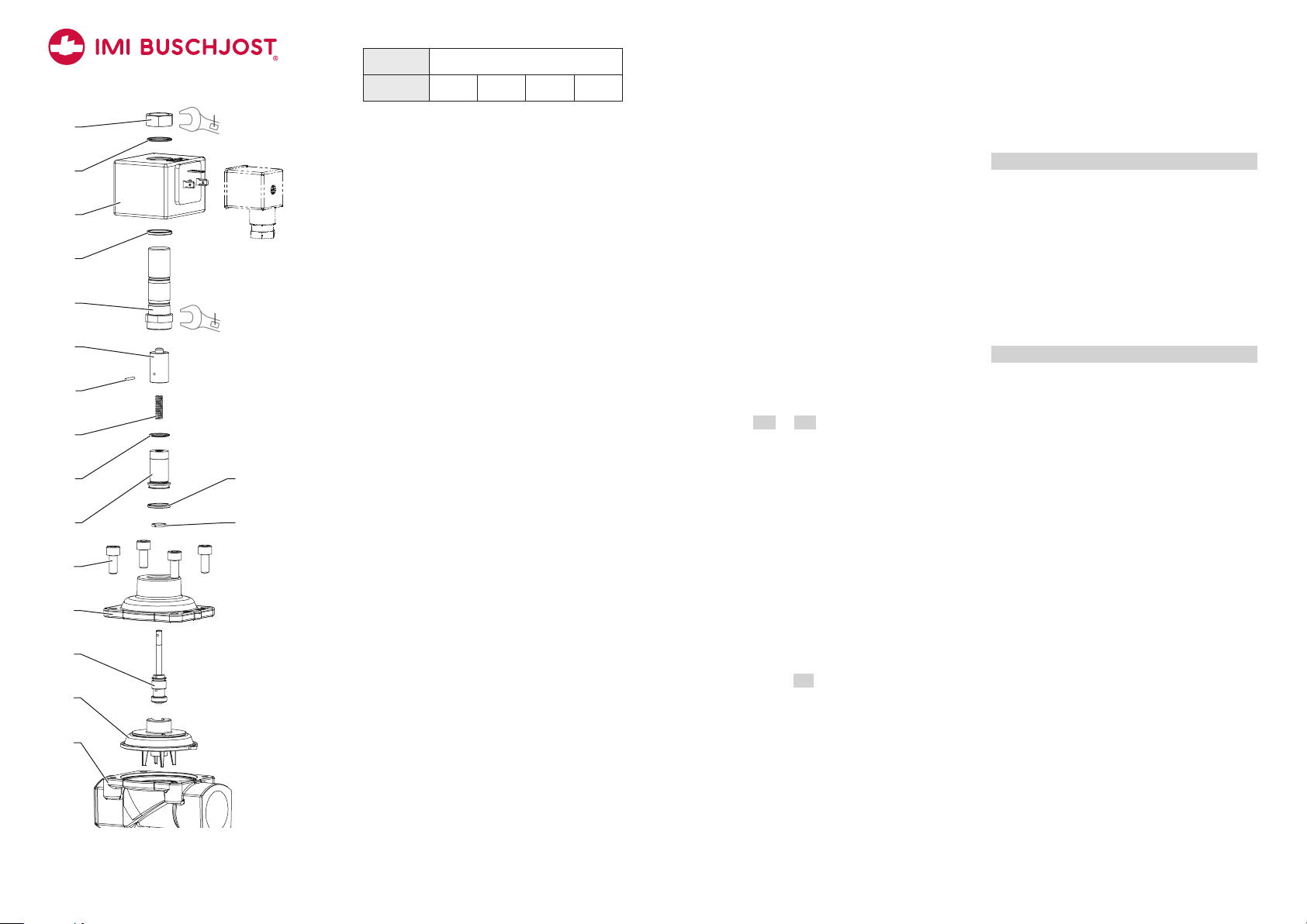
101
103
104
102
105
705
707
701
702
706
400
704
22
NC valve (example: G 1/2; series 82540)
ANC valve
solenoid 9151 9154 9176 9191
101 Valve body
102 Valve cover
103 Diaphragm ✗
104 Fixing screws
105 Compression spring ✗
400 Solenoid body
701 Core tube
702 O-ring ✗
704 Compression spring ✗
705 Core ✗
706 Spring clip
707 O-ring ✗
Unmounting solenoid
→Disconnect solenoid from valve by slightly
pulling on the spring clip 706 and pulling
the solenoid away from the core tube 701
with a rotational motion.
NOTICE O-ring 707 may get stripped away.
Not lose! Without this O-ring, the IP protec-
tive class is no longer guaranteed.
Disassemblingh valve parts
1. Loosen core tube 701 (wrench size 22).
2. Take off core tube 701 together with spring
clip 706 from core 705.
3.Pay attention to loose compression spring
704.
4. Slide O-rings 702 and 707 from core tube
701.
5.Loosen four fixing screws 104 from valve
cover 102.
6.Take off valve cover 102 from core 705.
7. Take off compression spring 105.
8.Take off diaphragm 103 and core 705 from
valve body 101.
9. Slide core 705 sideways out of holder of the
diaphragm 103.
→After disassembly, comply with the instruc-
tions in section 12.4 to 12.8.
Reassemblingh valve parts
1. Slide core 705 sideways in holder of the
diaphragm 103.
2. Place diaphragm 103 together with core
705 correctly positioned on valve body 101.
The diaphragm’s nose must be positioned in
the recess above the bleed orifice.
3.Put compression spring 105 centered on
diaphragm 103.
4. Put valve cover 102 on.
NOTICE Make sure that the diaphragm is
not jammed by valve cover.
5.Insert four fixing screws 104. Tighten fixing
screws crosswise. Observe tightening torque
– refer to table in 12.7.
6.Insert compression spring 704 into core
705.
7. Insert O-ring 702 into groove of core tube
701.
8.Slide core tube 701 over core 705 on valve
cover 102.
9. Insert spring clip 706 between core tube
701 and valve cover 102.
10. Screw and tighten core tube 701 (wrench
size 22) on valve cover 102.
Tightening torque 20 Nm ± 2 Nm
Mounting solenoid
1. Push o-ring 707 onto core tube until the
o-ring is flush to screw piece 703.
2. Arrange solenoid 400 parallel to spring clip
above core tube 701.
3.Slightly bend back spring clip 709.
Place solenoid 400 on the core tube 701.
Let solenoid snap to spring clip.
4. NOTICE Penetrating humidity may cause
corrosion of the solenoid cavity. Press
solenoid with a little twist towards valve
cover. Thus to ensure that solenoid is flush
to screw piece 703. Otherwise o-ring 707
will not seal sufficiently.
B1

10
11/2018 1377006.0000.10011
B1
BNC valve
solenoid 9301 9304 9356 9326
101 Valve body
102 Valve cover
103 Diaphragm ✗
104 Fixing screws
105 Compression spring ✗
400 Solenoid body
701 Core tube
702 O-ring ✗
704 Compression spring ✗
705 Core ✗
1501 Special hexagon nut
1502 O-ring (2x) ✗
Unmounting solenoid
1. Loosen special hexagon nut 1501 (wrench
size 19) and remove located below O-ring
1502.
2. Take off solenoid 400 from core tube 701.
NOTICE The O-ring 1502 may get stripped
away. Not lose! Without this O-ring, the IP
protective class is no longer guaranteed.
Disassemblingh valve parts
1. Loosen core tube 701 (wrench size 22).
2. Take off core tube 701 from core 705.
3.Pay attention to loose compression spring
704.
4. Slide O-rings 702 and 1502 from core tube
701.
5.Loosen four fixing screws 104 from valve
cover 102.
6.Take off valve cover 102 from core 705.
7. Take off compression spring 105.
8.Take off diaphragm 103 and core 705 from
valve body 101.
9. Slide core 705 sideways out of the holder of
the diaphragm 103.
→After disassembly, comply with instructions
in section 12.4 to 12.8.
Reassemblingh valve parts
1. Slide core 705 sideways in the holder of the
diaphragm 103.
2. Place diaphragm 103 together with core
705 correctly positioned on valve body 101.
The diaphragm’s nose must be positioned in
the recess above bleed orifice.
3.Put compression spring 105 centered on
diaphragm 103. Put valve cover 102 on.
NOTICE Make sure that the diaphragm is
not jammed by valve cover.
4. Insert the four fixing screws 104. Tighten
fixing screws crosswise. Observe tightening
torque – refer to table in 12.7.
5.Insert the compression spring 704 into core
705.
6.Insert O-ring 702 into the groove of core
tube 701.
7. Slide core tube 701 over the core 705 on
valve cover 102.
8.Screw and tighten core tube 701 (wrench
size 22) on valve cover 102.
Tightening torque 20 Nm ± 2 Nm
Mounting solenoid
1. Push O-ring 1502 onto core tube 701 until
it rests smooth on the tube‘s basis.
2. Place solenoid 400 on core tube 701.
3.Put O-ring 1502 onto core tube 701, in the
groove of solenoid 400.
4. Align solenoid 400 to the desired direction.
5.Fix solenoid 400 with hexagon screw 1501
(wrench size 19).
Tightening torque 12 Nm ± 2 Nm
101
103
104
102
105
705
400
704
701
702
1502
1501
1502
19
22
NC valve (example: G 3/4; series 82540)
11
11/2018 1377006.0000.10011
B1
101
103
702
104
102
105
707
705
703
704
706
400
701
36
NC valve (example: G 1 1/4; series 82540)
CNC valve
solenoid 9401 9404
101 Valve body
102 Valve cover
103 Diaphragm with spindle ✗
104 Fixing screws
105 Compression spring ✗
400 Solenoid body
701 Core tube
702 Straight pin ✗
703 Round plate
704 Compression spring ✗
705 Core ✗
706 Spring clip
707 O-ring ✗
Unmounting solenoid
1. A Push down the downwardly angled tab
of the spring clip 706. And move the spring
clip 706 towards the middle to release the
solenoid.
2.
B Take off the solenoid 400 from the core
tube 701.
NOTICE The O-ring 707 may get stripped
away. Not lose! Without this O-ring, the IP
protective class is no longer guaranteed.
A
B
Dissassemble solenoid 9401 (example)
Disassemblingh valve parts
1. Loose core tube 701 (wrench size 36).
2. Take off core tube 701 together with spring
clip 706 from core 705.
NOTICE Pay attention to loose components:
compression spring 704, round plate 703.
3.Slide O-ring 707 from core tube 701.
4. Press out straight pin 702 with a bolt
(Ø3mm) and take off core 705 from the
spindle of the diaphragm 103.
5.Loosen four fixing screws 104 from valve
cover 102.
6.Take off valve cover 102 from core 103.
7. Take off compression spring 105.
8.Take off diaphragm 103 from valve body
101.
→After disassembly, comply with instructions
in section 12.4 to 12.8.
Reassemblingh valve parts
1. Place the diaphragm 103 correctly posi-
tioned on the valve body 101. The dia-
phragm’s nose must be positioned in the
recess above bleed orifice.
2. Put compression spring 105 centered on
diaphragm 103. Put valve cover 102 on.
NOTICE Make sure that the diaphragm is
not jammed by valve cover.
3.Insert the four fixing screws 104. Tighten
fixing screws crosswise. Observe tightening
torque – refer to table in 12.7.
4. Put core 705 on diaphragm‘s spindle 103.
5.Align spindle and core 705 to cross bore.
6.Insert straight pin 702 flush to fix core 705
to diaphragm 103.
7. Insert compression spring 704 into core
705.
8.Insert round plate 703, with smooth side
facing the pole surface, into core tube 701
from below.
Note for overhead mounting: Fix round
plate 703 to pole surface with a little
lubricating grease.
9. Mount spring clip 706 on the guide shoulder
of the screw sleeve of core tube 701.
10. Slide core tube 701 over core 705 on
valve cover 102.
11. Screw core tube 701 (wrench size 36) on
valve cover 102 .
Tightening torque 80 Nm ± 5 Nm
Mounting solenoid
1. Push O-ring 707 onto core tube 701 until it
rests smooth on the tube‘s basis.
2.
A Attach solenoid 400 on core tube 701.
3.Move spring clip 706 so far that solenoid
400 can be lowered down to the downward-
ly angled tab.
4. Slightly lift the upwardly angled tab and
slide spring clip 706 towards solenoid.
5.
B Move spring clip 706 into engaged
position while pushing solenoid 400 onto
core tube.
NOTICE The downwardly angled tab of
spring clip must then grip the solenoid‘s
body securely.
B
A
Mounting solenoid 9401 (example)
12
11/2018 1377006.0000.10011
B1
DNO valve
solenoid 9151 9154 9176 9191
101 Valve body
102 Valve cover
103 Diaphragm ✗
104 Fixing screws
105 Valve spindle ✗
400 Solenoid body
701 Core tube
702 Core ✗
703 Guiding ring (2x) ✗
704 Compression spring ✗
705 Pole piece
706 O-ring ✗
707 O-ring ✗
708 Straight pin ✗
709 Spring clip
710 O-ring ✗
711 Round plate ✗
Unmounting solenoid
→Slightly bend back fixing clamp 709 and
pull solenoid with a twist upwards to take
off solenoid from core tube 701.
NOTICE O-ring 710 underneath the sole-
noid may get stripped away. Do not lose!
Without this O-ring the IP protection can no
longer be guaranteed.
Disassemblingh valve parts
1. Loosen core tube 701 at screw piece
(wrench size 22).
2. Take off core tube 701 together with spring
clip 709 from core 702 and pole piece 705.
3.Pay attention to loose round plate 711.
4. Slide o-ring 710 from core tube 701.
5.Press out straight pin 708 with a bolt
(Ø3mm) and take off core 702 and com-
pression spring 704 from valve spindle 105.
6.Take off guiding ring 703 from core 702 .
7. Also pull pole piece 705 from valve spindle
105.
8.Slide O-rings 706 and 707 from pole piece
705.
9. Loosen four fixing screws 104 from valve
cover 102.
10. Take off valve cover 102 from valve
spindle 105.
11.Take off diaphragm 103 and valve spindle
105 from valve body 101.
12. Slide valve spindle 105 sideways out of the
holder of diaphragm 103.
13. Take off guiding ring 703 from valve
spindle 702.
→After disassembly, comply with instructions
in section 12.4 to 12.8.
Reassemblingh valve parts
1. Slide valve spindle 105 sideways in the
holder of diaphragm 103.
2. Put guiding ring 703 into the groove of valve
spindle 105.
3.Place diaphragm 103 with valve spindle 105
correctly positioned on valve body 101. The
diaphragm’s nose must be positioned in the
recess above bleed orifice.
4. Put valve cover 102 on.
NOTICE Make sure that the diaphragm is
not jammed by valve cover.
5.Insert four fixing screws 104. Tighten fixing
screws crosswise. Observe tightening torque
– refer to table in 12.7.
6.Put O-rings 706 and 707 in the groove of
pole piece 705.
7. Place pole piece 705 over valve spindle 105
in valve cover 102.
8.Insert compression spring 704 into pole
piece 705.
9. Put core 702 on valve spindle 105.
10. Put guiding ring 703 into the groove of
core 702.
11. Align valve spindle 105 and core 702 to
cross bore.
12. Insert straight pin 708 flush to fix core
702 of diaphragm 703.
13. Insert round plate 711 into core tube 701
from below.
Note for overhead mounting: Fix round
plate 703 to pole surface with a little
lubricating grease.
14. Slide core tube 701 over core 702 and
pole piece 705 on valve cover 102.
15. Screw core tube 701 (wrench size 22) on
valve cover 102.
16. Insert spring clip 709 between core tube
701 and valve cover 102.
Tightening torque 20 Nm ± 2 Nm
Mounting solenoid
1. Push O-ring 707 onto core tube until the
O-ring is flush to screw piece 703.
2. Arrange solenoid 400 parallel to spring clip
above core tube 701.
3.Slightly bend back spring clip 709.
Place solenoid 400 on core tube 701.
Let solenoid snap to spring clip.
4. NOTICE Penetrating humidity may cause
corrosion of the solenoid cavity. Press the
solenoid with a little twist towards the valve
cover. Thus to ensure that solenoid is flush
to screw piece 703. Otherwise O-ring 707
will not seal sufficiently.
101
103
706
102
105
710
701
711
704
703
703
707
705
104
708
400
709
702
22
NO valve (example: G 1/2; series 82540)
13
11/2018 1377006.0000.10011
B1
101
103
707
104
102
105
1502
400
702
706
705
1501
704
701
1502
703
707
18
19
NO valve (example: G 1; series 82540)
ENO valve
solenoid 9301 9304 9356 9326
101 Valve body
102 Valve cover
103 Diaphragm ✗
104 Fixing screws
105 Valve spindle ✗
400 Solenoid body
701 Core tube
702 Core ✗
703 Guiding ring ✗
704 Compression spring ✗
705 Pole piece
706 Straight pin ✗
707 O-ring (2x) ✗
1501 Special hexagon screw
1502 O-ring (2x) ✗
Unmounting solenoid
1. Loosen special hexagon nut 1501 (wrench
size 19) and remove located below o-ring
1502.
2. Take off solenoid 400 from core tube 701.
NOTICE O-ring 1502 may get stripped away.
Do not lose! Without this O-ring, the IP
protective class is no longer guaranteed.
Disassemblingh valve parts
1. Loosen core tube 701 (wrench size 18).
2. Take off core tube 701 from core 702 and
pole piece 705.
3.Slide O-ring 1502 from core tube 701.
4. Press out straight pin 706 with a bolt
(Ø3mm) and take off core 702 and com-
pression spring 704 from valve spindle 105.
5.Also pull pole piece 705 from valve spindle
105.
6.Slide O-ring 707 from pole piece 705.
7. Loosen four fixing screws 104 from valve
cover 102.
8.Take off valve cover 102 from valve spindle
105.
9. Take off diaphragm 103 and valve spindle
105 from valve body 101.
10. Slide valve spindle 105 sideways out of the
holder of diaphragm 103.
11. Take off guiding ring 703 from valve
spindle 702.
→After disassembly, comply with instructions
in section 12.4 to 12.8.
Reassemblingh valve parts
1. Slide valve spindle 705 sideways into the
holder of diaphragm 103.
2. Put guiding ring 703 into the groove of valve
spindle 105.
3.Place diaphragm 103 with valve spindle 105
correctly positioned on valve body 101. The
diaphragm’s nose must be positioned in the
recess above bleed orifice.
4. Put valve cover 102 on.
NOTICE Make sure that diaphragm 103 is
not jammed by valve cover.
5.Insert four fixing screws 104. Tighten fixing
screws crosswise. Observe tightening torque
– refer to table in 12.7.
6.Put O-ring 707 in the groove of pole piece
705.
7. Place pole piece 705 above valve spindle
105 in valve cover102.
8.Insert compression spring 704 into pole
piece 705.
9. Put core 702 on valve spindle 105.
10. Align valve spindle 105 and core 702 to
the cross bore.
11. Insert straight pin 706 flush to fix the core
702 to diaphragm 103.
12. Slide core tube 701 over core 702 and
pole piece 705 on valve cover 102.
13. Screw core tube 701 (wrench size 18) on
valve cover 102.
Tightening torque 20 Nm ± 2 Nm
Mounting solenoid
1. Push O-ring 1502 onto core tube 701 until
it rests smooth on the tube‘s basis.
2. Place solenoid 400 on core tube 701.
3.Put O-ring 1502 onto core tube 701, in the
groove of solenoid 400.
4. Align the solenoid 400.
5.Fix tsolenoid 400 with hexagon screw 1501
(wrench size 19).
Tightening torque 12 Nm ± 2 Nm
Buschjost GmbH
Detmolder Str. 256
D-32545 Bad Oeynhausen
P.O. Box 10 02 52-53
D-32502 Bad Oeynhausen
Phone: 0 57 31/7 91-0
Fax: 0 57 31/79 11 79
www.imi-precision.com
buschjost@imi-precision.com
1377006.0000.10011 14
11/2018
13 Re-commissioning
1. Check valve’s switching function without
fluid (refer to 10.1).
2. Flood the valve slowly (refer to 10.2).
3.Perform a leak and strength tests (refer to
12.2).
14 Decommissioning
1. !DANGER Disconnect the solenoid from
power supply.
2.
!WARNING Depressurise the pipe system.
Drain the pipework completely. Handle water
polluting fluids in accordance with local
regulations.
3.
!CAUTION Leave the solenoid to cool
down.
4. Disconnect the connection cable from the
device socket or from the connection area of
the solenoid.
5.
!CAUTION Wear protective gloves. Loosen
pipe connection.
6.Disassemble the valve.
7. Drain and dry the valve.
15 Replace complete valve
1. Disassemble the valve as described in chap-
ter 14 “Decommissioning”.
2. Assembly the new valve as described in
chapter 7 “Mouting”.
3.Connect the solenoid as described in chap-
ter 8 “Connect solenoid electrically”.
16 Trouble shooting
→Observe safety information and instructions
in chapter 12 “Maintenance”.
Error table
Not function
Possible cause: the solenoid coil defective
Remedy: replace solenoid
Possible cause: the control voltage must be
≥90% of its nominal value.
Remedy: measure the control voltage directly in
front of the solenoid. If the operating voltage is
lower or a long cable is used, a heavier conduc-
tor (crosssection up to 1.5 mm2) must be chosen
to keep the voltage drop small.
Impaired function
Possible cause: diaphragm soiled
Remedy: clean the control bore in the diaphragm
Possible cause: core jammed
Remedy: clean core and core tube
Possible cause: valve seat leaking
Remedy: a) clean valve body
b) clean or replace diaphragm
c) valve seat damaged
inadmissible operating conditions
Possible cause: operating pressure too high or
too low
Remedy: check maximum operating pressure and
reduce pressure accordingly.
17 Return
1. Disassemble the valve as described in chap-
ter 14 “Decommissioning”.
2. Save the “goods return declaration” form –
PDF file available online at:
http://www.buschjost.com/service/
other-documents/goods-return-declaration/
3.Fill in the return form and work through the
requirements listed there.
4. !CAUTION Consider the weight of the
valve in the choice of packaging.
5.Attach the printed, completed an signed
goods return declaration to the package.
18 Disposal
1. Disassemble the valve as described in chap-
ter 14 “Decommissioning”.
2. Disassemble the valve parts to enable reu-
sable materials to be recycled.
3.Dispose of the valve parts as appropriate for
their materials:
Material Way of disposal
Valve body, valve
cover
Metal recycling
Diaphragm, O-rings Industrial waste
similar category to
domestic refuse
Solenoid
(copper wire)
Electrical waste
recycling
19 Directives and certificates
Note to Pressure Equipment Directive (PED)
This valves of this series, including the
connection size DN 25 (G 1), are according to
Art. 4 § 3 of the Pressure Equipment Directive
2014/68/EU (PED). This means interpretation
an production are in accordance to engineers
practice wellknown in the member countries.
The CE-marking at the valve refers not to the
PED. Thus the declaration of conformity is not
longer applicable for this directive.
For valves > DN 25 (G 1) Art. 4 § (1) No. 1.4
of the Pressure Equipment Directive 2014/68/
EU (DGRL) applies. The basic requirements of
the Enclosure I of the PED must be fulfilled.
The CE-marking at the valve includes the PED.
A certificate of conformity of this directive will
be available on request.
Notes on EEC Directive
The valves shall be provided with an elec-
trical circuit which ensures the limits of the
harmonised standards EN 61000-6-3 and
EN 61000-6-1 are observed, and hence the
requirements of the Electromagnetic Compati-
bility Guideline (2004/108/EG) satisfield. The
CE-marking is related to this EU-requirements.
B1
This manual suits for next models
3
Table of contents
Other IMI BUSCHJOST Control Unit manuals

Popular Control Unit manuals by other brands


Nidec
Nidec SM-Applications Series user guide

Lenze
Lenze E94AZMAC Mounting instructions

Gaymar
Gaymar SPR Plus III Service manual

Trenz Electronic
Trenz Electronic TE0712 200 2C10 Series Schematics

Aliaxis
Aliaxis VEE Series manual

Telit Wireless Solutions
Telit Wireless Solutions GC864 Series Hardware user's guide

Telit Wireless Solutions
Telit Wireless Solutions NE310H2 Hardware Design Guide

Honeywell
Honeywell L4068 manual

Chore-Time
Chore-Time Chore-Tronics Model 8 User& installer's manual

Siemens
Siemens 3VM9.88-0LB10 operating instructions

Lincoln industrial
Lincoln industrial MP1 owner's manual

Dallmer
Dallmer Stausafe RS manual