Honeywell L4068 User manual
Other Honeywell Control Unit manuals

Honeywell
Honeywell Alwa-Kombi-4 User manual

Honeywell
Honeywell 7800 SERIES Operation manual
Honeywell
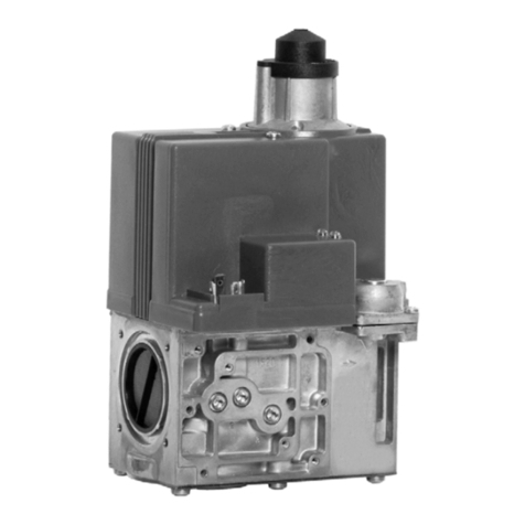
Honeywell BCU 460 Manual
Honeywell
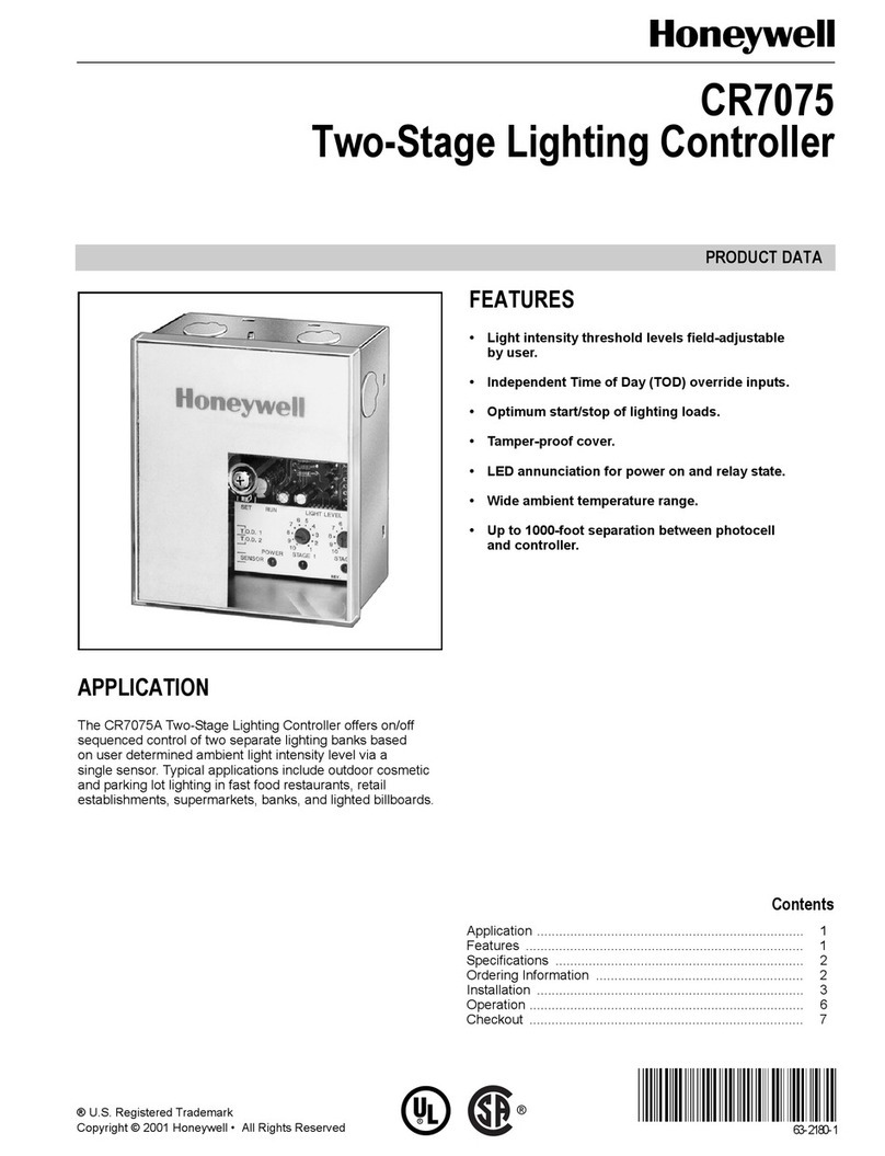
Honeywell V4730B User manual
Honeywell
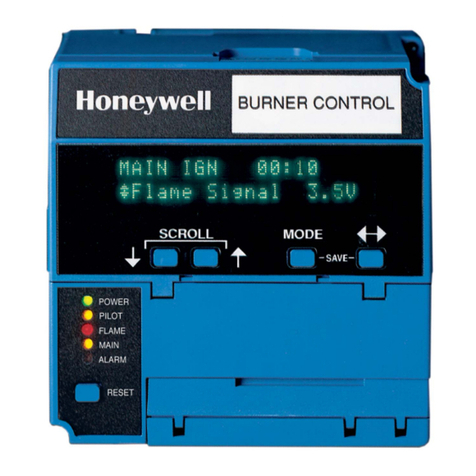
Honeywell CR7075 Operation manual
Honeywell
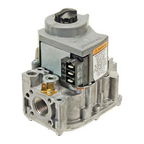
Honeywell 7800 SERIES User manual
Honeywell
Honeywell VR8205 User manual
Honeywell
Honeywell VS8510 User manual
Honeywell
Honeywell VR8215S User manual
Honeywell
Honeywell ADEMCO 4204 User manual
Honeywell
Honeywell VP527A User manual

Honeywell
Honeywell Satronic TFI 812 Series User manual
Honeywell
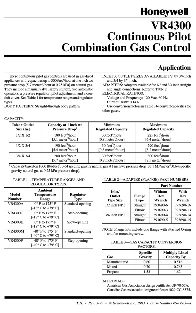
Honeywell VR4300 User manual
Honeywell
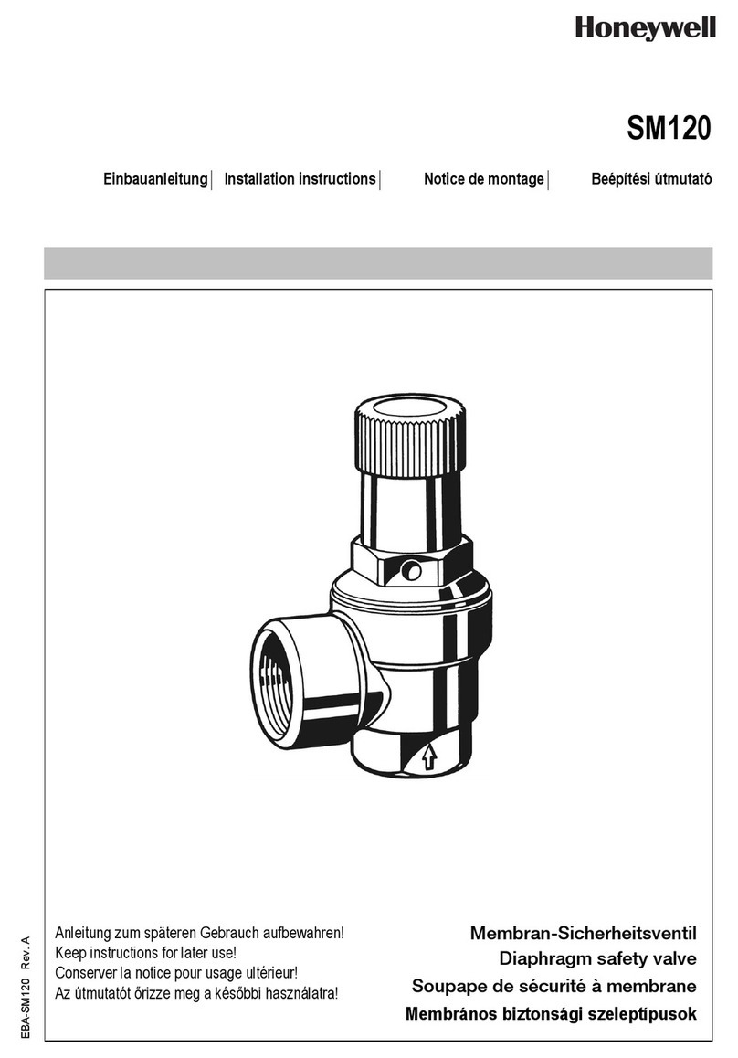
Honeywell SM120 User manual
Honeywell
Honeywell SILENT KNIGHT Farenhyt Series User manual
Honeywell
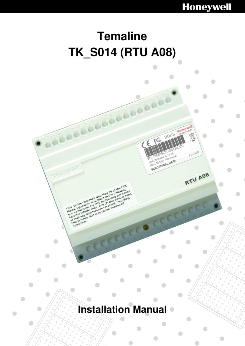
Honeywell Temaline TK-S014 User manual
Honeywell
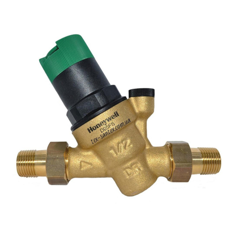
Honeywell D05FS User manual

Honeywell
Honeywell ControlEdge 900 platform User manual
Honeywell
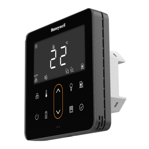
Honeywell TR80 Installation guide
Honeywell
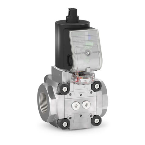
Honeywell Krom Schroeder VAN Series User manual
Popular Control Unit manuals by other brands

Festo
Festo Compact Performance CP-FB6-E Brief description

Elo TouchSystems
Elo TouchSystems DMS-SA19P-EXTME Quick installation guide

JS Automation
JS Automation MPC3034A user manual

JAUDT
JAUDT SW GII 6406 Series Translation of the original operating instructions

Spektrum
Spektrum Air Module System manual

BOC Edwards
BOC Edwards Q Series instruction manual

KHADAS
KHADAS BT Magic quick start

Etherma
Etherma eNEXHO-IL Assembly and operating instructions

PMFoundations
PMFoundations Attenuverter Assembly guide

GEA
GEA VARIVENT Operating instruction

Walther Systemtechnik
Walther Systemtechnik VMS-05 Assembly instructions

Altronix
Altronix LINQ8PD Installation and programming manual
