Nidec SM-Applications Series User manual

User Guide
SM-Applications
Modules and
Motion Processors
SM-Applications
SM-Applications Lite
SM-Applications Plus
SM-Applications Lite V2
Digitax ST Indexer
Digitax ST Plus
Part Number: 0471-0062-04
Issue: 4

Original Instructions
For the purposes of compliance with the EU Machinery Directive 2006/42/EC, the English version of this manual
is the Original Instructions. Manuals in other languages are Translations of the Original Instructions.
Documentation
Manuals are available to download from the following locations: http://www.drive-setup.com/ctdownloads
The information contained in this manual is believed to be correct at the time of printing and does not form part of
any contract. The manufacturer reserves the right to change the specification of the product and its performance,
and the contents of the manual, without notice.
Warranty and Liability
In no event and under no circumstances shall the manufacturer be liable for damages and failures due to misuse,
abuse, improper installation, or abnormal conditions of temperature, dust, or corrosion, or failures due to
operation outside the published ratings. The manufacturer is not liable for consequential and incidental damages.
Contact the supplier of the drive for full details of the warranty terms.
Environmental policy
Control Techniques Ltd operates an Environmental Management System (EMS) that conforms to the
International Standard ISO 14001.
Further information on our Environmental Policy can be found at: http://www.drive-setup.com/environment
Restriction of Hazardous Substances (RoHS)
The products covered by this manual comply with European and International regulations on the Restriction of Haz-
ardous Substances including EU directive 2011/65/EU and the Chinese Administrative Measures for Restriction of
Hazardous Substances in Electrical and Electronic Products.
Disposal and Recycling (WEEE)
REACH legislation
EC Regulation 1907/2006 on the Registration, Evaluation, Authorisation and restriction of Chemicals (REACH)
requires the supplier of an article to inform the recipient if it contains more than a specified proportion of any
substance which is considered by the European Chemicals Agency (ECHA) to be a Substance of Very High
Concern (SVHC) and is therefore listed by them as a candidate for compulsory authorisation.
Further information on our compliance with REACH can be found at: http://www.drive-setup.com/reach
Registered Office
Nidec Control Techniques Ltd
The Gro
Newtown
Powys
SY16 3BE
UK
Registered in England and Wales. Company Reg. No. 01236886.
When electronic products reach the end of their useful life, they must not be disposed of along
with domestic waste but should be recycled by a specialist recycler of electronic equipment.
Control Techniques products are designed to be easily dismantled into their major component
parts for efficient recycling. The majority of materials used in the product are suitable for
recycling.
Product packaging is of good quality and can be re-used. Large products are packed in wooden
crates. Smaller products are packaged in strong cardboard cartons which have a high recycled
fibre content. Cartons can be re-used and recycled. Polythene, used in protective film and bags
for wrapping the product, can be recycled. When preparing to recycle or dispose of any product
or packaging, please observe local legislation and best practice.

Copyright
The contents of this publication are believed to be correct at the time of printing. In the interests of a commitment
to a policy of continuous development and improvement, the manufacturer reserves the right to change the
specification of the product or its performance, or the contents of the guide, without notice.
All rights reserved. No parts of this guide may be reproduced or transmitted in any form or by any means,
electrical or mechanical including photocopying, recording or by an information storage or retrieval system,
without permission in writing from the publisher.
Copyright © 23 January 2018 Nidec Control Techniques Ltd

4SM-Applications Modules & Motion Processors User Guide
Issue Number: 4
Contents
1 Safety Information .................................................................7
1.1 Warnings, Cautions and Notes ................................................................7
1.2 Important safety information. Hazards.
Competence of designers and installers .................................................7
1.3 Responsibility ..........................................................................................7
1.4 Compliance with regulations ...................................................................7
1.5 Electrical hazards ....................................................................................8
1.6 Stored electrical charge ...........................................................................8
1.7 Mechanical hazards ................................................................................8
1.8 Access to equipment ...............................................................................8
1.9 Environmental limits ................................................................................9
1.10 Hazardous environments ........................................................................9
1.11 Motor .......................................................................................................9
1.12 Mechanical brake control ........................................................................9
1.13 Adjusting parameters ..............................................................................9
1.14 Electromagnetic compatibility (EMC) ......................................................9
2 Introduction ..........................................................................10
2.1 Features for Different Module Variants .................................................10
2.2 Solutions Module identification ..............................................................12
2.3 Conventions used in this guide .............................................................12
2.4 PC Development Software ....................................................................13
2.5 User Knowledge ....................................................................................13
3 Installation ............................................................................14
3.1 General Installation ...............................................................................14
3.2 SMARTCARD Installation .....................................................................14
3.3 Electrical Connections ...........................................................................14
3.4 Connections ..........................................................................................16
3.5 CTNet Cable ..........................................................................................16
3.6 CTNet Network Termination ..................................................................17
3.7 EIA-RS485 Connections .......................................................................18
3.8 Digital I/O Connections ..........................................................................20
3.9 Port Isolation .........................................................................................20

SM-Applications Modules & Motion Processors User Guide 5
Issue Number: 4
4 Getting Started .....................................................................21
4.1 Using SyPTPro and SyPTLite ...............................................................21
4.2 Connecting the PC to the Second Processor ........................................21
4.3 CTNetAPI routing ..................................................................................22
4.4 Configuring Communications within SyPTPro .......................................22
4.5 Creating a Node in SyPTPro .................................................................23
4.6 Porting UD70 programs to the Second Processor ................................23
4.7 Using SyPTLite ......................................................................................24
4.8 DPL Programming Basics .....................................................................25
4.9 Program Example ..................................................................................26
4.10 Downloading Programs .........................................................................27
5 Parameters ...........................................................................28
5.1 Overview ...............................................................................................28
5.2 Saving Parameters ................................................................................28
5.3 Configuration Parameters .....................................................................29
5.4 Menus 70-75 - PLC Registers ...............................................................43
5.5 Menu 85 - Timer Function Parameters ..................................................44
5.6 Menu 86 - Digital I/O Parameters ..........................................................46
5.7 Menu 88 - Status Parameters ...............................................................48
5.8 Menu 90 - General Parameters .............................................................50
5.9 Menu 91 - Fast Access Parameters ......................................................61
5.10 Menus 18,19 - Application Parameters .................................................67
5.11 Menu 20 - Application Menu ..................................................................68
6 Communications ..................................................................69
6.1 EIA-RS485 Serial Communications Port ...............................................69
6.2 CTNet ....................................................................................................75
6.3 Second Processor Mapping Parameters (fieldbus) ...............................76
7 DPL Programming ...............................................................78
7.1 Program Header ....................................................................................78
7.2 Tasks .....................................................................................................79
7.3 Variables ...............................................................................................81
7.4 Parameters ............................................................................................83
7.5 Operators ..............................................................................................84
7.6 Basic DPL Commands ..........................................................................85
7.7 User Defined Function Blocks ...............................................................90
8 Freeze and Marker ...............................................................93
8.1 Freeze input ..........................................................................................93
8.2 Freeze input ..........................................................................................94
8.3 Marker pulse ..........................................................................................96

6SM-Applications Modules & Motion Processors User Guide
Issue Number: 4
9 CTSync .................................................................................97
9.1 Overview ...............................................................................................97
9.2 Connections ..........................................................................................97
9.3 Limitations .............................................................................................98
9.4 CTSync Function Blocks .......................................................................98
9.5 Motion Engine .......................................................................................99
9.6 Virtual Master Example .......................................................................102
10 Inter-option Synchronization ..........................................104
10.1 Overview .............................................................................................104
10.2 Inter-Option Synchronization example 1 .............................................104
10.3 Inter-option Synchronization example 2 ..............................................107
10.4 Position control tasks ..........................................................................111
11 Diagnostics ......................................................................112
11.1 Run-time Errors ...................................................................................112
11.2 Drive Display Trip Codes .....................................................................112
11.3 Second Processor Run-time Error Codes ...........................................113
11.4 Handling Run-Time Errors with the ERROR task ................................115
11.5 Resource monitoring ...........................................................................116
11.6 Support ................................................................................................118
12 Migration Guide ...............................................................119
12.1 Drive Parameter Differences ...............................................................119
12.2 UD70 Parameters ................................................................................119
12.3 General Features ................................................................................121
12.4 Second Processor Porting aid ............................................................122
13 Quick Reference ..............................................................124

SM-Applications Modules & Motion Processors User Guide 7
Issue Number: 4
Safety
Information
Introduction Installation Getting
Started Parameters
DPL
Programming Communications
Freeze and
Marker
CTSync Inter-option
Synchronization
Diagnostics Migration
Guide
Quick
Reference Index
1 Safety Information
1.1 Warnings, Cautions and Notes
1.2 Important safety information. Hazards. Competence of
designers and installers
This guide applies to products which control electric motors either directly (drives) or
indirectly (controllers, option modules and other auxiliary equipment and accessories).
In all cases the hazards associated with powerful electrical drives are present, and all
safety information relating to drives and associated equipment must be observed.
Specific warnings are given at the relevant places in this guide.
Drives and controllers are intended as components for professional incorporation into
complete systems. If installed incorrectly they may present a safety hazard. The drive
uses high voltages and currents, carries a high level of stored electrical energy, and is
used to control equipment which can cause injury. Close attention is required to the
electrical installation and the system design to avoid hazards either in normal operation
or in the event of equipment malfunction. System design, installation, commissioning/
start-up and maintenance must be carried out by personnel who have the necessary
training and competence. They must read this safety information and this guide
carefully.
1.3 Responsibility
It is the responsibility of the installer to ensure that the equipment is installed correctly
with regard to all instructions given in this guide. They must give due consideration to
the safety of the complete system, so as to avoid the risk of injury both in normal
operation and in the event of a fault or of reasonably foreseeable misuse.
The manufacturer accepts no liability for any consequences resulting from
inappropriate, negligent or incorrect installation of the equipment.
1.4 Compliance with regulations
The installer is responsible for complying with all relevant regulations, such as national
wiring regulations, accident prevention regulations and electromagnetic compatibility
(EMC) regulations. Particular attention must be given to the cross-sectional areas of
conductors, the selection of fuses or other protection, and protective ground (earth)
connections.
This guide contains instructions for achieving compliance with specific EMC standards.
A Warning contains information, which is essential for avoiding a safety hazard.
A Caution contains information, which is necessary for avoiding a risk of damage to the
product or other equipment.
A Note contains information, which helps to ensure correct operation of the product.
WARNING
CAUT IO N
NOTE

8SM-Applications Modules & Motion Processors User Guide
Issue Number: 4
All machinery to be supplied within the European Union in which this product is used
must comply with the following directives:
2006/42/EC Safety of machinery.
2014/30/EU: Electromagnetic Compatibility.
1.5 Electrical hazards
The voltages used in the drive can cause severe electrical shock and/or burns, and
could be lethal. Extreme care is necessary at all times when working with or adjacent to
the drive. Hazardous voltage may be present in any of the following locations:
• AC and DC supply cables and connections
• Output cables and connections
• Many internal parts of the drive, and external option units
Unless otherwise indicated, control terminals are single insulated and must not be
touched.
The supply must be disconnected by an approved electrical isolation device before
gaining access to the electrical connections.
The STOP and Safe Torque Off functions of the drive do not isolate dangerous voltages
from the output of the drive or from any external option unit.
The drive must be installed in accordance with the instructions given in this guide.
Failure to observe the instructions could result in a fire hazard.
1.6 Stored electrical charge
The drive contains capacitors that remain charged to a potentially lethal voltage after the
AC supply has been disconnected. If the drive has been energized, the AC supply must
be isolated at least ten minutes before work may continue.
1.7 Mechanical hazards
Careful consideration must be given to the functions of the drive or controller which
might result in a hazard, either through their intended behaviour or through incorrect
operation due to a fault. In any application where a malfunction of the drive or its control
system could lead to or allow damage, loss or injury, a risk analysis must be carried out,
and where necessary, further measures taken to reduce the risk - for example, an over-
speed protection device in case of failure of the speed control, or a fail-safe mechanical
brake in case of loss of motor braking.
With the sole exception of the Safe Torque Off function, none of the drive
functions must be used to ensure safety of personnel, i.e. they must not be used
for safety-related functions.
The Safe Torque Off function may be used in a safety-related application. The system
designer is responsible for ensuring that the complete system is safe and designed
correctly according to the relevant safety standards.
The design of safety-related control systems must only be done by personnel with the
required training and experience. The Safe Torque Off function will only ensure the
safety of a machine if it is correctly incorporated into a complete safety system. The
system must be subject to a risk assessment to confirm that the residual risk of an
unsafe event is at an acceptable level for the application.
1.8 Access to equipment
Access must be restricted to authorized personnel only. Safety regulations which apply
at the place of use must be complied with.

SM-Applications Modules & Motion Processors User Guide 9
Issue Number: 4
Safety
Information
Introduction Installation Getting
Started Parameters
DPL
Programming Communications
Freeze and
Marker
CTSync Inter-option
Synchronization
Diagnostics Migration
Guide
Quick
Reference Index
1.9 Environmental limits
Instructions in this guide regarding transport, storage, installation and use of the
equipment must be complied with, including the specified environmental limits. This
includes temperature, humidity, contamination, shock and vibration. Drives must not be
subjected to excessive physical force.
1.10 Hazardous environments
The equipment must not be installed in a hazardous environment (i.e. a potentially
explosive environment).
1.11 Motor
The safety of the motor under variable speed conditions must be ensured.
To avoid the risk of physical injury, do not exceed the maximum specified speed of the
motor.
Low speeds may cause the motor to overheat because the cooling fan becomes less
effective, causing a fire hazard. The motor should be installed with a protection
thermistor. If necessary, an electric forced vent fan should be used.
The values of the motor parameters set in the drive affect the protection of the motor.
The default values in the drive must not be relied upon. It is essential that the correct
value is entered in the Motor Rated Current parameter.
1.12 Mechanical brake control
Any brake control functions are provided to allow well co-ordinated operation of an
external brake with the drive. While both hardware and software are designed to high
standards of quality and robustness, they are not intended for use as safety functions,
i.e. where a fault or failure would result in a risk of injury. In any application where the
incorrect operation of the brake release mechanism could result in injury, independent
protection devices of proven integrity must also be incorporated.
1.13 Adjusting parameters
Some parameters have a profound effect on the operation of the drive. They must not
be altered without careful consideration of the impact on the controlled system.
Measures must be taken to prevent unwanted changes due to error or tampering.
1.14 Electromagnetic compatibility (EMC)
Installation instructions for a range of EMC environments are provided in the relevant
Power Installation Guide. If the installation is poorly designed or other equipment does
not comply with suitable standards for EMC, the product might cause or suffer from
disturbance due to electromagnetic interaction with other equipment. It is the
responsibility of the installer to ensure that the equipment or system into which the
product is incorporated complies with the relevant EMC legislation in the place of use.

10 SM-Applications Modules & Motion Processors User Guide
Issue Number: 4
2 Introduction
2.1 Features for Different Module Variants
Modern variable speed drives offer a multitude of in-built features such as ramp control,
PID loops, simple position control, etc. However this functionality is limited. The drive
can only do so many things and when it comes to controlling more complex
applications, users often have to resort to using external equipment such as PLCs to
control the drive from a system point of view.
However the flexibility of certain drives can be substantially increased by using the
Second Processors. These Second Processors provide an additional processor for the
drive and allow the user to utilise existing, or write their own, application-specific
software. They also offer powerful networking capabilities so many drives (and other
equipment) can be connected together to communicate process wide information thus
offering a complete application solution. The Second Processors are solutions modules
that can be fitted to expansion slots in the supported drives or are embedded in the
Digitax drives. The Second Processor are powered from the drive’s internal power
supply
Specifications for SM-Applications
• High speed dedicated microprocessor
• 384 kb Flash memory for user program
• 80 kb user program memory
• EIA-RS485 port offering ANSI, Modbus-RTU slave and master and Modbus-
ASCII slave and master protocols
• CTNet high speed network connection offering up to 5 Mbit/s data rate.
• Two 24V digital inputs
• Two 24V digital outputs
• Task based programming system allowing for real-time control of drive and
process
•CTSync
Specifications for SM-Applications Lite
• High speed dedicated microprocessor
• SyPTLite 10 kb executable memory
• SyPTPro V2.3.1 or later 384 kb executable memory, 80 kb user memory.
• SyPTPro V2.2.0 150 kb executable memory, 20 kb user memory.
• Versions prior to V2.2.0 100 kb executable memory, 20 kb user memory.
• Task based programming system allowing for real-time control of drive and
process.

SM-Applications Modules & Motion Processors User Guide 11
Issue Number: 4
Safety
Information Introduction Installation Getting
Started Parameters
DPL
Programming Communications
Freeze and
Marker
CTSync
Inter-option
Synchronization Diagnostics Migration
Guide
Quick
Reference Index
Specifications for SM-Applications Plus
• Enhanced high speed dedicated microprocessor
• 384 kb Flash memory for user program
• 80 kb user program memory
• EIA-RS485 port offering ANSI, Modbus-RTU slave and master and Modbus-
ASCII slave and master protocols
• CTNet high speed network connection offering up to 5 Mbit/s data rate.
• Two 24V digital inputs
• Two 24V digital outputs
• Task based programming system allowing for real-time control of drive and
process
•CTSync
Specifications for SM-Applications Lite V2
• Only supported on SyPTPro V2.4.0 or later
• Only supported on SyPTLite V1.4.0 or later
• Enhanced high speed dedicated microprocessor
• SyPTLite 10 kb executable memory
• 384 kb executable memory, 80 kb user memory.
• Task based programming system allowing for real-time control of drive and
process.
Specifications for Digitax ST Plus Embedded Processor.
• Enhanced high speed dedicated microprocessor
• 384 kb Flash memory for user program
• 80kb user program memory
• EIA-RS485 port offering ANSI, Modbus-RTU slave and master and Modbus-
ASCII slave and master protocols
• CTNet high speed network connection offering up to 5 Mbit/s data rate.
• Two 24V digital inputs
• Two 24V digital outputs
• Task based programming system allowing for real-time control of drive and
process
•CTSync
Specifications for Digitax ST Indexer Embedded Processor.
• Only supported on SyPTPro V2.4.0 or later
• Only supported on SyPTLite V1.4.0 or later
• Enhanced high speed dedicated microprocessor
• SyPTLite 10 kb executable memory
• 384 kb executable memory, 80 kb user memory.
• Task based programming system allowing for real-time control of drive and
process.

12 SM-Applications Modules & Motion Processors User Guide
Issue Number: 4
2.2 Solutions Module identification
Figure 2-1 Second Processor
The Second Processors can be identified by:
1. The label located on the underside of the Solutions Module.
2. The colour coding across the front of the Solutions Module.
SM-Applications: Mint Green
SM-Applications Lite: White
SM-Applications Plus: Light Moss Green
SM-Applications Lite V2: White
Figure 2-2 SM-Applications label
2.3 Conventions used in this guide
This manual contains information relating to the SM-Applications, SM-Applications Lite,
SM-Applications Lite V2 and SM-Applications Plus option modules and embedded
processors on Digitax ST Indexer and Digitax ST Plus.
Throughout the manual these will be referred to generically as Second Processors or
modules. Should a particular section refer to one or two of these modules only, the
reference will be to those modules by their name directly.
The configuration of the host drive and Solutions Module is done using menus and
parameters. A menu is a logical collection of parameters that have similar functionality.
The SM-Applications Plus module, SM-Applications Lite V2 module and the Digitax ST
Plus has a slightly faster variant of the SM-Applications microprocessor, thereby
increasing performance of the module over the SM-Applications.
NOTE
SM-Applications
Issue: 0 STDJ41
Ser No : 3000005001
Solutions Module
name
Customer
and date code
Serial number
Issue
number

SM-Applications Modules & Motion Processors User Guide 13
Issue Number: 4
Safety
Information Introduction Installation Getting
Started Parameters
DPL
Programming Communications
Freeze and
Marker
CTSync
Inter-option
Synchronization Diagnostics Migration
Guide
Quick
Reference Index
In the case of a Solutions Module, the parameters will appear in menu 15, 16 or 17 for
the drive depending on the slot the module is fitted into. In the case of embedded
solutions these will appear in menu 17. The menu is determined by the number before
the decimal point.
The method used to determine the menu or parameter is as follows:
•Prxx.00 - signifies any menu and parameter number 00.
•Prx.XX - where xsignifies the the menu allocated to the Solutions Module (this
could be 15, 16 or 17) and XX signifies the parameter number.
2.4 PC Development Software
Application programs for the Second Processors may be developed by the user with the
SyPT software tools. Users who are familiar with the UD70 product for the Unidrive
Classic may already be familiar with this software.
SyPTPro offers various tools to help in developing solutions:
• Configuration editor for configuring drives and connections on CTNet, EtherNet, CT-
RTU, CT-TCP and MD29MON networks.
• IEC61131-3 based ladder and function block programming
• Native DPL language programming.
• Watch window for monitoring drive and option parameters, and program variables.
• Single-stepping and breakpoint debugging facilities.
With SyPTPro you may connect to the Second Processors by either:
• Direct connection to the EIA-RS485 port on the front of the Drive.
• Connecting to one or more options on a CTNet network (a CTNet interface card for
the PC will be required). See section Features on pages 8, 9 & 10 for availability of
CTNet on your Second Processor
• Ethernet.
SyPTPro runs under Microsoft WindowsTM NT4/2000/XP.
2.5 User Knowledge
If developing custom application software it is beneficial to have some understanding of
real-time task and event driven programming. A rudimentary understanding of the
BASIC programming language is also beneficial but not essential. The ladder diagram
(LD) and function block diagram (FBD) facilities of SyPTPro make it much easier for
people familiar with PLCs to migrate.
This User Guide assumes the user has at least superficial knowledge of Microsoft
WindowsTM.

14 SM-Applications Modules & Motion Processors User Guide
Issue Number: 4
3 Installation
3.1 General Installation
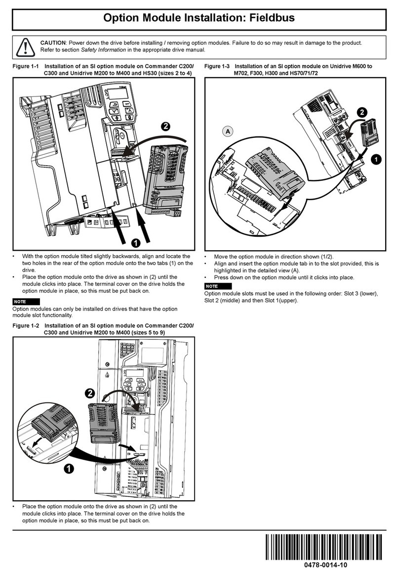
The installation of a Solutions Module is illustrated in Figure 3-1.
Figure 3-1 Fitting a Solutions Module
The Solutions Module connector is located on the underside of the module (1). Push
this into the Solutions Module slot located on the drive until it clicks into place (2). Note
that some drives require a protective tab to be removed from the Solutions Module slot.
For further information, refer to the appropriate drive manual.
3.2 SMARTCARD Installation
Refer to the relevant drive documentation for SMARTCARD support.
3.3 Electrical Connections
Figure 3-2 SM-Apps/SM-Apps Plus/Digitax ST Plus - Front View
The terminal functions are given in Table 3-1.
Before installing or removing a Solutions Module in any drive, ensure the AC supply has
been disconnected for at least 10 minutes and refer to Chapter 1 Safety Information on
page 7. If using a DC bus supply ensure this is fully discharged before working on any
drive or Solutions Module.
WARNING
1
2
1234 5 678 9 10111213

SM-Applications Modules & Motion Processors User Guide 15
Issue Number: 4
Safety
Information Introduction
Installation
Getting
Started Parameters
DPL
Programming Communications
Freeze and
Marker
CTSync
Inter-option
Synchronization Diagnostics Migration
Guide
Quick
Reference Index
Please note that SM-Applications Lite, SM-Applications Lite V2 and ST Indexer do not
have these terminals.
Table 3-1 Module Connectors
Table 3-3 Digital Output Specifications
Please ensure that the drive is off before removing any modules.
Please refer to your installation sheet for more information.
NOTE
Terminal Function Description
1 0V SC 0V connection for EIA-RS485 port
2 /RX EIA-RS485 Receive line (negative). Incoming.
3 RX EIA-RS485 Receive line (positive). Incoming.
4 /TX EIA-RS485 Transmit line (negative). Outgoing.
5 TX EIA-RS485 Transmit line (positive). Outgoing.
6 CTNet A CTNet data line
7 CTNet Shield Shield connection for CTNet
8 CTNet B CTNet data line
9 0V 0V connection for digital I/O
10 DIO Digital input 0
11 DI1 Digital input 1
12 DO0 Digital output 0
13 DO1 Digital output 1
Table 3-2 Digital Input Specifications
Terminal 10 / Digital Input 0
Terminal 11 / Digital Input 1
Type Positive logic IEC 61131-2
Maximum Input Voltage +/- 30V
Switching Threshold 9.5 V +/- 0.3 V
Load 2 mA at +15 V
Terminal 12 / Digital Output 0
Terminal 13 / Digital Output 1
Type Positive logic when active
Output Voltage 0 / 24V
Nominal max. output 20 mA
When inactive they are effectively floating.
NOTE

16 SM-Applications Modules & Motion Processors User Guide
Issue Number: 4
3.4 Connections
To connect the module to the CTNet network, make the connections as shown in the
diagram below.
Figure 3-3 CTNet Network Connections
The shields of both cables should be twisted together and connected into the centre
terminal of the 3-way terminal block. This “pigtail” should be kept as short as possible.
This design guarantees shield continuity.
3.5 CTNet Cable
CTNet cable has a single twisted pair plus overall screening. One set of data terminals
is provided. This has the advantage that if the terminal block is unplugged the continuity
of the CTNet network is not broken.
CTNet networks run at high data rates, and require cable specifically designed to carry
high frequency signals. Low quality cable will attenuate the signals, and may render the
signal unreadable for the other nodes on the network.The only approved CTNet cable is
that supplied by Control Techniques.
This User Guide covers only the basics of connecting a CTNet network. Please refer to
the CTNet User Guide for full information. Digitax connections are given in the Digitax
ST Plus manual. SM-Applications Lite, SM-Applications Lite V2 and ST Indexer do not
have these CTNet Connections.
NOTE
CTNet shield
CTNet+
CTNet-

SM-Applications Modules & Motion Processors User Guide 17
Issue Number: 4
Safety
Information Introduction
Installation
Getting
Started Parameters
DPL
Programming Communications
Freeze and
Marker
CTSync
Inter-option
Synchronization Diagnostics Migration
Guide
Quick
Reference Index
3.6 CTNet Network Termination
It is very important in high-speed communications networks that the network
communications cable is fitted with the specified termination resistor network at each
end of the cable. This prevents signals from being reflected back down the cable and
causing interference.
The termination resistance should match as closely as possible the impedance of the
cable. For the recommended Control Techniques green CTNet cable, an 82 0.25 W
termination resistor should be fitted across the CTNet+ and CTNet- data lines at BOTH
ends of the cable run.
Figure 3-4 CTNet Network Termination
3.6.1 CTNet Cable Screen Connections
The cable shields should be linked together at the point where they emerge from the
cable, and formed into a short pigtail to be connected to CTNet shield connection on the
terminal block, as already shown.
For safety, the CTNet shield must be connected to earth at one point. This earth
connection is to prevent the cable screen from becoming live in the event of
catastrophic failure of another device on the CTNet network or along the cable run.
3.6.2 Maximum Network Length and Number of Nodes
The maximum number of nodes that can be connected to a single CTNet network is
255, however a network may need to be split into segments, separated by repeaters.
The maximum length of network cable for a CTNet network is dependent on the baud
rate and number of nodes...Refer to CTNet user guide.
Failure to terminate a network correctly can seriously affect the operation of the network.
If the correct termination resistors are not fitted, the noise immunity of the network is
greatly reduced.
WARNING
If too many termination resistors are fitted on a CTNet network, the network will be over-
loaded, resulting in reduced signal levels. This may cause nodes to miss some bits of
information, resulting in transmission errors being reported. If network overload is
excessive, the signal levels may be so low that nodes cannot detect any network
activity at all.
NOTE

18 SM-Applications Modules & Motion Processors User Guide
Issue Number: 4
Repeaters can be purchased from Control Techniques. The table below shows the part
numbers for the different repeaters available.
Please refer to the CTNet User Guide for further guidance on these points.
3.7 EIA-RS485 Connections
Please note that SM-Applications Lite, SM-Applications Lite V2 and ST Indexer do not
have these connections.
The EIA-RS485 port is available for lower-speed communications (up to 115,200bit/s).
As standard the port supports the CT-ANSI slave, Modbus-RTU master and slave, and
Modbus-ASCII master and slave protocols. Both 2 and 4-wire connections are possible.
More information on the use of the EIA-RS485 port can be found in Chapter
6Communications on page 69.
A host controller can operate up to thirty-two EIA RS485 devices with the use of line
repeaters. Each transmitter and receiver of Control Techniques devices loads the line by
2 unit loads. Therefore in two-wire mode, each Control Techniques device loads the line
by 4 unit-loads. This means that no more than a total of seven devices can be
connected in a single group, allowing up to 4 unit-loads for the line repeater. Up to 15
devices can be connected if four-wire mode is used.
3.7.1 4 Wire EIA-RS485 Network
The diagram below shows the connections required for a 4 wire EIA-RS485 network,
using a master controller with an EIA-RS485 port. SM-Applications Modules & Motion
Processors can be configured to act as master controllers, but this requires DPL
programming to control the network.
An EIA-RS232 to EIA-RS485 converter is required to allow a standard PC serial port to
communicate with a 4 wire EIA-RS485 network.
Part
Numer Description
4500-0033 AI3-485X - Rev A
4500-0083 AI3-485X-CT - Rev D (Port 1), Rev A (Ports 2 and 3)
4500-0082 AI3-CT - Rev D
4500-0032 AI2-485X/FOG-ST - Rev A (Fibre Optic)
4500-0081 AI2-CT/FOG-ST - Rev D (Fibre-Optic)
0V /Rx Rx /Tx Tx
12345
SM-Applications Module
Slave
5 4 3 2 1
9 8 7 6
UD70, MD29, Unidrive, Mentor
II
Slave
1200.25W
termination resistors
0V /Rx Rx /Tx Tx
12345
Master

SM-Applications Modules & Motion Processors User Guide 19
Issue Number: 4
Safety
Information Introduction
Installation
Getting
Started Parameters
DPL
Programming Communications
Freeze and
Marker
CTSync
Inter-option
Synchronization Diagnostics Migration
Guide
Quick
Reference Index
3.7.2 2 Wire EIA-RS485 Network
The diagram below shows the connections required for a 2 wire EIA-RS485 network,
using a master controller with an EIA-RS485 port. SM-Applications Modules & Motion
Processors can be configured to act as master controllers, but this requires DPL
programming to control the network.
An EIA-RS232 to EIA-RS485 converter with “intelligent transceiver switching” (also
known as “magic” EIA-RS485 converters) is required to allow a standard PC serial port
to communicate with a 2 wire EIA-RS485 network. An example of a “magic” converter is
the MA485F converter from Amplicon.
3.7.3 Grounding
It is recommended for safety that the shield of the communications cable be connected
by a low-inductance path to a ‘clean’ earth point. This must only be done at one point.
3.7.4 Routing of the cable
A data communications cable should not run parallel to any power cables, especially
ones that connect drives to motors. If parallel runs are unavoidable, ensure a minimum
spacing of 300 mm (1 foot) between the communications cable and the power cable.
Cables crossing one another at right-angles are unlikely to give trouble. The maximum
cable length for a EIA-RS485 link is 1200 metres (4,000 feet). This is at low baud rates
only. The higher the baud rate the lower the maximum cable length.
3.7.5 Termination
When a long-distance multi-drop EIA-RS485 system is used, the transmit and receive
pairs should have a termination resistor of 120 fitted across them in order to reduce
signal reflections. However, at the lower data rates this is not so critical.
A “magic” converter is not required if the master controller has an RTS control output.
This output is enabled when the master is transmitting, and disabled when the master is
not transmitting. Control Techniques software packages (UniSoft, MentorSoft and
SystemWise) do NOT switch the RTS line.
0V / Rx Rx /Tx Tx
12345
SM-Applications Module
Sl ave Commander SE
Slave
0V TxRxB TxRxA
37 2
0V / Rx Rx / Tx Tx
12345
Master
1200.25W
termination resi stor
NOTE

20 SM-Applications Modules & Motion Processors User Guide
Issue Number: 4
3.8 Digital I/O Connections
The SM-Applications, SM-Applications Plus and Digitax ST Plus are equipped with 2
digital inputs, known as DIGIN0 and DIGIN1, and 2 digital outputs, known as DIGOUT0
and DIGOUT1. These inputs and outputs can be read/controlled from the user program
loaded into the SM-Applications Modules & Motion Processors .
The digital outputs are a positive logic arrangement such that they are at +24V when
active and will supply up to 20 mA of current. When inactive they are effectively floating.
The digital outputs are protected against short-circuit or overload. The trip threshold is
20 mA, and if tripped both outputs will be deactivated.
The digital I/O are controlled using menu 86 - refer to section 5.6 Menu 86 - Digital I/O
Parameters on page 46.
3.9 Port Isolation
The digital input/output ports are connected to the main drive control circuits.
The CTNet and EIA-RS485 ports have supplementary insulation from the input/output
ports, giving overall double insulation from the power circuit.
They have simple separation (functional insulation) from each other.
0V
DIGIN0
DIGIN1
DIGOUT1
DIGOUT0
139121110
The I/O circuits are isolated from the power circuits by basic insulation (single insulation)
only. The installer must ensure that external control circuits are insulated from human
contact by at least one layer of insulation (supplementary insulation) rated for the AC
supply voltage
To maintain the double insulation status of the data ports:
• All circuits to which either port is connected must have protective separation (i.e.
double insulation or single insulation with grounding)
• All circuits to which the drive control circuits are connected must have at least basic
insulation from live parts.
WARNING
WARNING
This manual suits for next models
6
Table of contents
Other Nidec Control Unit manuals
Popular Control Unit manuals by other brands

Victron energy
Victron energy Venus GX manual

Beninca
Beninca MBE operating instructions

Murphy
Murphy LM500 installation instructions

VADO
VADO Axces AX-VAL-149-CP Installation & user manual

American Standard
American Standard Ultima 6045.051 installation instructions

Bang & Olufsen
Bang & Olufsen STB-C Mounting instruction