IMI SENSORS 682A09 User manual

Model 682A09
IN-LINE ICP TO 4-20 MA OUTPUT VELOCITY CONVERTER
Installation and Operating Manual
For assistance with the operation of this product,
contact PCB Piezotronics, Inc.
Toll-free: 800-959-4464
24-hour SensorLine: 716-684-0001
Fax: 716-684-3823
E-mail: [email protected]
Web: www.imi-sensors.com

The information contained in this document supersedes all similar information that
may be found elsewhere in this manual.
Service –Due to the sophisticated
nature of the sensors and associated
instrumentation provided by PCB
Piezotronics, user servicing or repair is
not recommended and, if attempted,
may void the factory warranty. Routine
maintenance, such as the cleaning of
electrical connectors, housings, and
mounting surfaces with solutions and
techniques that will not harm the
physical material of construction, is
acceptable. Caution should be observed
to ensure that liquids are not permitted
to migrate into devices that are not
hermetically sealed. Such devices
should only be wiped with a dampened
cloth and never submerged or have
liquids poured upon them.
Repair –In the event that equipment
becomes damaged or ceases to
operate, arrangements should be made
to return the equipment to PCB
Piezotronics for repair. User servicing or
repair is not recommended and, if
attempted, may void the factory
warranty.
Calibration –Routine calibration of
sensors and associated instrumentation
is recommended as this helps build
confidence in measurement accuracy
and acquired data. Equipment
calibration cycles are typically
established by the users own quality
regimen. When in doubt about a
calibration cycle, a good “rule of thumb”
is to recalibrate on an annual basis. It is
also good practice to recalibrate after
exposure to any severe temperature
extreme, shock, load, or other
environmental influence, or prior to any
critical test.
PCB Piezotronics maintains an ISO-
9001 certified metrology laboratory and
offers calibration services, which are
accredited by A2LA to ISO/IEC 17025,
with full traceability to SI through
N.I.S.T. In addition to the normally
supplied calibration, special testing is
also available, such as: sensitivity at
elevated or cryogenic temperatures,
phase response, extended high or low
frequency response, extended range,
leak testing, hydrostatic pressure
testing, and others. For information on
standard recalibration services or
special testing, contact your local PCB
Piezotronics distributor, sales
representative, or factory customer
service representative.
Returning Equipment –Following
these procedures will ensure that your
returned materials are handled in the
most expedient manner. Before
returning any equipment to PCB
Piezotronics, contact your local
distributor, sales representative, or
factory customer service representative
to obtain a Return Warranty, Service,
Repair, and Return Policies and
Instructions Materials Authorization
(RMA) Number. This RMA number
should be clearly marked on the outside
of all package(s) and on the packing
Service, Repair, and Return
Policies and Instructions

list(s) accompanying the shipment. A
detailed account of the nature of the
problem(s) being experienced with the
equipment should also be included
inside the package(s) containing any
returned materials.
A Purchase Order, included with the
returned materials, will expedite the
turn-around of serviced equipment. It is
recommended to include authorization
on the Purchase Order for PCB to
proceed with any repairs, as long as
they do not exceed 50% of the
replacement cost of the returned
item(s). PCB will provide a price
quotation or replacement
recommendation for any item whose
repair costs would exceed 50% of
replacement cost, or any item that is not
economically feasible to repair. For
routine calibration services, the
Purchase Order should include
authorization to proceed and return at
current pricing, which can be obtained
from a factory customer service
representative.
Contact Information –International
customers should direct all inquiries to
their local distributor or sales office. A
complete list of distributors and offices
can be found at www.pcb.com.
Customers within the United States may
contact their local sales representative
or a factory customer service
representative. A complete list of sales
representatives can be found at
www.pcb.com. Toll-free telephone
numbers for a factory customer service
representative, in the division
responsible for this product, can be
found on the title page at the front of this
manual. Our ship to address and
general contact numbers are:
PCB Piezotronics, Inc.
3425 Walden Ave.
Depew, NY14043 USA
Toll-free: (800) 828-8840
24-hour SensorLineSM: (716) 684-0001
Website: www.pcb.com
PCB工业监视和测量设备 - 中国RoHS2公布表
PCB Industrial Monitoring and Measuring Equipment - China RoHS 2 Disclosure Table
部件名称
有害物质
铅(Pb)
汞
(Hg)
镉
(Cd)
六价铬(Cr(VI))
多溴联苯 (PBB)
多溴二苯醚(PBDE)
住房
O
O
O
O
O
O
PCB板
X
O
O
O
O
O
电气连接器
O
O
O
O
O
O
压电晶体
X
O
O
O
O
O
环氧
O
O
O
O
O
O
铁氟龙
O
O
O
O
O
O
电子
O
O
O
O
O
O
厚膜基板
O
O
X
O
O
O
电线
O
O
O
O
O
O
电缆
X
O
O
O
O
O
塑料
O
O
O
O
O
O
焊接
X
O
O
O
O
O
铜合金/黄铜
X
O
O
O
O
O
本表格依据 SJ/T 11364 的规定编制。
O:表示该有害物质在该部件所有均质材料中的含量均在 GB/T 26572 规定的限量要求以下。
X:表示该有害物质至少在该部件的某一均质材料中的含量超出 GB/T 26572 规定的限量要求。
铅是欧洲RoHS指令2011/65/ EU附件三和附件四目前由于允许的豁免。
CHINA RoHS COMPLIANCE

DOCUMENT NUMBER: 21354
DOCUMENT REVISION: D
ECN: 46162
Component Name
Hazardous Substances
Lead
(Pb)
Mercury
(Hg)
Cadmium
(Cd)
Chromium VI
Compounds
(Cr(VI))
Polybrominated
Biphenyls
(PBB)
Polybrominated
Diphenyl
Ethers (PBDE)
Housing
O
O
O
O
O
O
PCB Board
X
O
O
O
O
O
Electrical
Connectors
O
O
O
O
O
O
Piezoelectric
Crystals
X
O
O
O
O
O
Epoxy
O
O
O
O
O
O
Teflon
O
O
O
O
O
O
Electronics
O
O
O
O
O
O
Thick Film
Substrate
O
O
X
O
O
O
Wires
O
O
O
O
O
O
Cables
X
O
O
O
O
O
Plastic
O
O
O
O
O
O
Solder
X
O
O
O
O
O
Copper Alloy/Brass
X
O
O
O
O
O
This table is prepared in accordance with the provisions of SJ/T 11364.
O: Indicates that said hazardous substance contained in all of the homogeneous materials for this part is below the limit
requirement of GB/T 26572.
X: Indicates that said hazardous substance contained in at least one of the homogeneous materials for this part is above
the limit requirement of GB/T 26572.
Lead is present due to allowed exemption in Annex III or Annex IV of the European RoHS Directive 2011/65/EU.

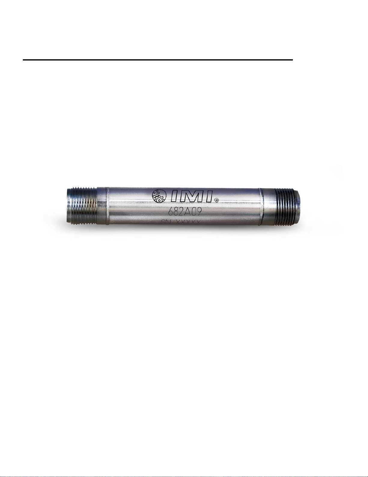
Model 682A09
Industrial in line ICP to 4 to 20 mA converter
Installation and Operating Manual
For assistance with the operation of this product, contact
the IMI-Sensors Division of PCB Piezotronics, Inc.
Division toll-free:
24-hour SensorLine:
Fax: 716-684-3823
E-mail: imi@pcb.com
Document Number 43343
Revision: B
ECO: 46419

Warranty, Service, Repair, and
Return Policies and Instructions
The information contained in this document supersedes all similar information that
may be found elsewhere in this manual.
Total Customer Satisfaction - PCB
Piezotronics guarantees Total Customer
Satisfaction. If, at any time, for any
reason, you are not completely satisfied
with any PCB product, PCB will repair,
replace, or exchange it at no charge. You
may also choose to have your purchase
price refunded in lieu of the repair,
replacement, or exchange of the product.
Service - Due to the sophisticated nature
of the sensors and associated
instrumentation provided by PCB
Piezotronics, user servicing or repair is
not recommended and, if attempted, may
void the factory warranty. Routine
maintenance, such as the cleaning of
electrical connectors, housings, and
mounting surfaces with solutions and
techniques that will not harm the
physical material of construction, is
acceptable. Caution should be observed
to insure that liquids are not permitted to
migrate into devices that are not
hermetically sealed. Such devices should
only be wiped with a dampened cloth
and never submerged or have liquids
poured upon them.
Repair - In the event that equipment
becomes damaged or ceases to operate,
arrangements should be made to return
the equipment to PCB Piezotronics for
repair. User servicing or repair is not
recommended and, if attempted, may
void the factory warranty.
Calibration - Routine calibration of
sensors and associated instrumentation is
recommended as this helps build
confidence in measurement accuracy and
acquired data. Equipment calibration
cycles are typically established by the
users own quality regimen. When in
doubt about a calibration cycle, a good
"rule of thumb" is to recalibrate on an
annual basis. It is also good practice to
recalibrate after exposure to any severe
temperature extreme, shock, load, or
other environmental influence, or prior
to any critical test.
PCB Piezotronics maintains an ISO-
9001 certified metrology laboratory and
offers calibration services, which are
accredited by A2LA to ISO/IEC 17025,
with full traceability to N.I.S.T. In
addition to the normally supplied
calibration, special testing is also
available, such as: sensitivity at elevated
or cryogenic temperatures, phase
response, extended high or low
frequency response, extended range, leak
testing, hydrostatic pressure testing, and
others. For information on standard
recalibration services or special testing,
contact your local PCB Piezotronics
distributor, sales representative, or
factory customer service representative.
Returning Equipment - Following
these procedures will insure that your
returned materials are handled in the
most expedient manner. Before returning
any equipment to PCB Piezotronics,
contact your local distributor, sales
representative, or factory customer
service representative to obtain a Return

Materials Authorization (RMA)
Number. This RMA number should be
clearly marked on the outside of all
package(s) and on the packing list(s)
accompanying the shipment. A detailed
account of the nature of the problem(s)
being experienced with the equipment
should also be included inside the
package(s) containing any returned
materials.
A Purchase Order, included with the
returned materials, will expedite the
turn-around of serviced equipment. It is
recommended to include authorization
on the Purchase Order for PCB to
proceed with any repairs, as long as they
do not exceed 50% of the replacement
cost of the returned item(s). PCB will
provide a price quotation or replacement
recommendation for any item whose
repair costs would exceed 50% of
replacement cost, or any item that is not
economically feasible to repair. For
routine calibration services, the Purchase
Order should include authorization to
proceed and return at current pricing,
which can be obtained from a factory
customer service representative.
Warranty - All equipment and repair
services provided by PCB Piezotronics,
Inc. are covered by a limited warranty
against defective material and
workmanship for a period of one year
from date of original purchase. Contact
PCB for a complete statement of our
warranty. Expendable items, such as
batteries and mounting hardware, are not
covered by warranty. Mechanical
damage to equipment due to improper
use is not covered by warranty.
Electronic circuitry failure caused by the
introduction of unregulated or improper
excitation power or electrostatic
discharge is not covered by warranty.
Contact Information - International
customers should direct all inquiries to
their local distributor or sales office. A
complete list of distributors and offices
can be found at www.pcb.com.
Customers within the United States may
contact their local sales representative or
a factory customer service
representative. A complete list of sales
representatives can be found at
www.pcb.com. Toll-free telephone
numbers for a factory customer service
representative, in the division
responsible for this product, can be
found on the title page at the front of this
manual. Our ship to address and general
contact numbers are:
PCB Piezotronics, Inc.
3425 Walden Ave.
Depew, NY 14043 USA
Toll-free: (800) 828-8840
24-hour SensorLineSM: (716) 684-0001
Website: www.pcb.com
Operating Guide with Enclosed Warranty Information
3425 Walden Avenue, Depew, New York 14043-2495
Phone (716) 684-0003
Fax (716) 684-3823
Toll Free Line 1-800-959-41 Ml

A PCB PIEZOTRONICS DIV.
Table ofContents
Introduction
General Features Page 3
Operation and Wiring
Standard Wiring Page 3
Suggested Cabling Page 4
RV (Raw Vibration) Output Page 4

A PCB PIEZOTRONICS DIV.
Page 3
Introduction
The Model 682A09 Series Industrial in line ICP to 4-20mA converter transfers the signal from any 100 mV/g ICP
industrial accelerometer to 4-20mA overall vibration velocity. The converter outputs a 4-20mA signal that is
proportional to the overall velocity and raw acceleration of the machinery. Ideal for monitoring the vibration of
process equipment such as fans, motors and pumps, the output of the converter is routed to a PLC, DCS or
SCADA system and used for process control or predictive maintenance.
General Features
•Loop powered, works with an open analog channel on PLC, DCS or SCADA system.
•Vibration range in velocity scaled for 0-1 inches per second peak
•Allows for continuous vibration monitoring of critical applications.
•Reduces the need for sophisticated vibration analysis requirements.
•RV (Raw Vibration) output for conducting frequency analysis and machinery diagnostics.
•Readily interfaces to existing process control and predictive maintenance equipment.
•Rugged stainless steel construction for applications in harsh environments.
Operation and Wiring
Standard Wiring
The Model 682A09 Series operates from a standard 2-wire, 4-20mA loop. If using a loop power, attach at 3-Pin
connector side the positive (+) input from the power supply to Pin A and the negative (-) input from the power
supply to Pin B. Pin C is a buffered raw acceleration output (Fig. 1). At ICP side (2-Pin connector) attach Pin A (+)
to positive terminal of ICP sensor and Pin B (-) to negative (common) terminal of ICP sensor (Fig. 2).
Figure 1 - wiring: loop powered

A PCB PIEZOTRONICS DIV.
Page 4
Suggested Cabling
For connecting 100 mV/g ICP accelerometer to 682A09 converter:
IMI suggests using model 052APXXXAP cable where XXX is the cable length in feet. For example, model
052AP010AP is a 10 ft. polyurethane cable, 2-socket MIL (AP) on each end. The 2-socket MIL connector (AP)
mates to most any 2-pin MIL industrial accelerometer and also the model 682A09. Pictures of this cable and
connector can be found at IMI’s website www.imisensors.com.
For connecting 682A09 converter to PLC, DCS, SCADA system:
IMI suggests using model 059BVXXXBZ cable where XXX is the cable length in feet. For example, model
059BV010BZ is a 10 ft. polyurethane cable, 3-socket MIL (BV) to blunt termination. The 3-socket MIL (BV)
connector mates to the output of the 682A09. Wiring to acquisition is color coded as follows:
Red - connect to pos (+) loop-powered input on PLC, DCS, SCADA system
Black or Green –connect to neg (-) loop-power input on PLC, DCS, SCADA system
White –100 mV/g analog sensor signal for frequency analysis, route to BNC for walk-up measurement
with portable data collector
RV Output
The RV (raw vibration) output is a pass-through for the 100 mV/g industrial accelerometer connected to the
model 682A09. The frequency range and accuracy of the signal will be dependent upon the accelerometer used.
Data collectors or analyzers can use this vibration signal for further analysis. Contact IMI if you require more
information on the accelerometer being connected to model 682A09.
Notes:
- The RV Signal Negative has to be isolated from any grounding. If this terminal is grounded, the 4-
20mA loop will short, causing no output.
- The RV output signal is ideally suited for use with portable battery powered data collectors or
analyzers.

Model Number
682A09
IN-LINE ICP TO 4-20 MA OUTPUT VELOCITY CONVERTER
Revision: A
ECN #: 35125
Performance
ENGLISH
SI
Input Signal(ICP Accelerometer)
100 mV/g
10.2 mV/(m/s²)
Frequency Response(-3dB ±2dB)
600 to 60,000 cpm
10 to 1000 Hz
Measurement Range
0.0 to 1.0 in/sec pk
0.0 to 25.4 mm/s pk
Output Range
4 to 20 mA
4 to 20 mA
Broadband Resolution
0.01 in/sec pk
0.26 mm/s pk
Environmental
Temperature Range
-40 to 185 °F
-40 to 85 °C
Temperature Response(Sensitivity Deviation)
≤15 %
≤15 %
Electrical
Excitation Voltage
20 to 30 VDC
20 to 30 VDC
Electrical Isolation(Case)
>10
8
ohm
>10
8
ohm
Settling Time(within 2% of value)
<60 sec
<60 sec
Load Resistance
50 (Vs-20) ohm
50 (Vs-20) ohm
Physical
Size (Height x Diameter)
4.0 in x 0.621 in
101.6 mm x 15.8 mm
Weight
2.5 oz
71 gm
Housing Material
Stainless Steel
Stainless Steel
Electrical Connector(#1)
2-Pin MIL-C-5015
2-Pin MIL-C-5015
Electrical Connection Position(#1)
Sensor End
Sensor End
Electrical Connections(#1)(Pin A)
AC IN Pos
AC IN Pos
Electrical Connections(#1)(Pin B)
AC IN Neg
AC IN Neg
Electrical Connector(#2)
3-Pin MIL-C-5015
3-Pin MIL-C-5015
Electrical Connection Position(#2)
Output End
Output End
Electrical Connections(#2)(Pin A)
4-20 mA Pos (+)
4-20 mA Pos (+)
Electrical Connections(#2)(Pin B)
4-20 mA Neg & AC OUT Neg
4-20 mA Neg & AC OUT Neg
Electrical Connections(#2)(Pin C)
AC OUT Pos
AC OUT Pos
Sealing
Welded Hermetic
Welded Hermetic
All specifications are at room temperature unless otherwise specified.
In the interest of constant product improvement, we reserve the right to change specifications without notice.
OPTIONAL VERSIONS
Optional versions have identical specifications and accessories as listed for the standard model
except where noted below. More than one option may be used.
Entered: DMW Engineer: JSQ Sales: JMS
Approved: TB
Spec Number:
Date: 3/7/2011 Date: 3/7/2011 Date: 3/7/2011 Date: 3/7/2011
43341
3425 Walden Avenue, Depew, NY 14043
Phone: 800-959-4464
Fax: 716-684-3823
E-Mail: imi@pcb.com

1
1
2
2
A A
B B
CODE
IDENT. NO.
52681
DWG. NO.
SCALE: SHEET
DRAWN CHECKED ENGINEER
TITLE
UNLESS OTHERWISE SPECIFIED TOLERANCES ARE:
DIMENSIONS IN MILLIMETERS
[ IN BRACKETS ]
ANGLES 2 DEGREES
3425 WALDEN AVE. DEPEW, NY 14043
(716) 684-0001 E-MAIL: sales@pcb.com
DIMENSIONS IN INCHES
ANGLES 2 DEGREES
FILLETS AND RADII
.003 - .005
FILLETS AND RADII
0.07 - 0.13
OUTLINE DRAWING
43342
1 OF 1
FULL
MODEL 682A09
VIBRATION TRANSMITTER
DECIMALS XX ±.03
XXX ±.010
DECIMALS X ± 0.8
XX ± 0.25
JDM 5/23/14 ECB 5/23/14 GGS 5/23/14
AB
C
A
B
43342
PCB Piezotronics Inc. claims proprietary rights in
the information disclosed hereon. Neither it nor any
reproduction thereof will be disclosed to others
without the written consent of PCB Piezotronics Inc.
REVISIONS
REV DESCRIPTION DIN
B UPDATED NOTCH 42942
4.01 [101.9]
.621 [15.77]
5/8-24 UNEF - 2A
ELECTRICAL CONNECTOR
2-PIN (MIL-C-5015)
5/8-24 UNEF - 2A
ELECTRICAL CONNECTOR
3-PIN (MIL-C-5015)
4-20 MA POS
4-20 MA NEG
ANALOG SIGNAL
(RV, RVVO)
OUT
SIGNAL / POWER GROUND
Table of contents


