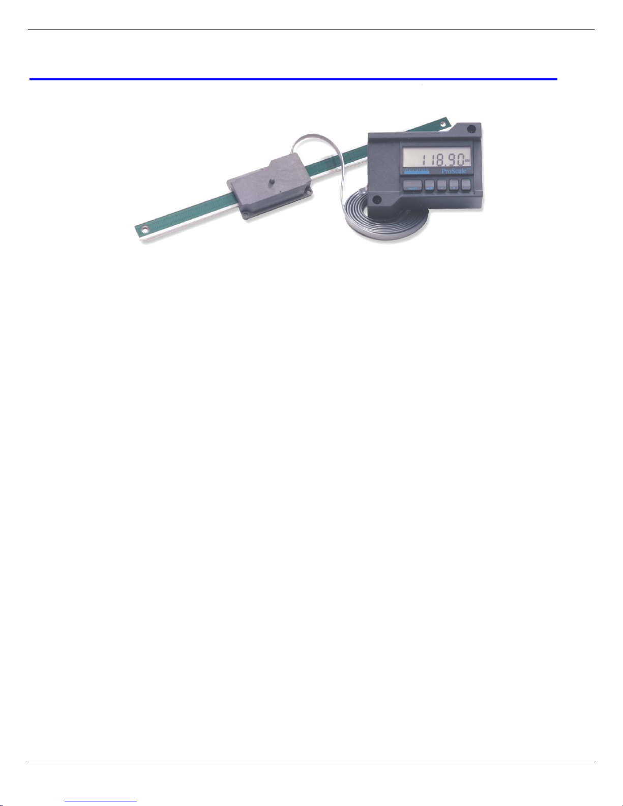
Mitutoyo America Corp. - ProScale Series 950 DRO 3 of 34
Table of Contents
SECTION 1 GENERAL INFORMATION................................................................................................................... 4
Introduction ..................................................................................................................................................... 4
ProScale Terminology..................................................................................................................................... 4
Scales ............................................................................................................................................................. 5
Readheads...................................................................................................................................................... 6
Displays........................................................................................................................................................... 7
Replacement Parts.......................................................................................................................................... 7
Product Specifications..................................................................................................................................... 8
SECTION 2 950-404 AND 950-405.................................................................................................................... 9
Installation:...................................................................................................................................................... 9
Calibration:.................................................................................................................................................... 10
Calibration:.................................................................................................................................................... 11
Maintenance:................................................................................................................................................. 11
SECTION 3 950-406 AND 950-407.................................................................................................................. 12
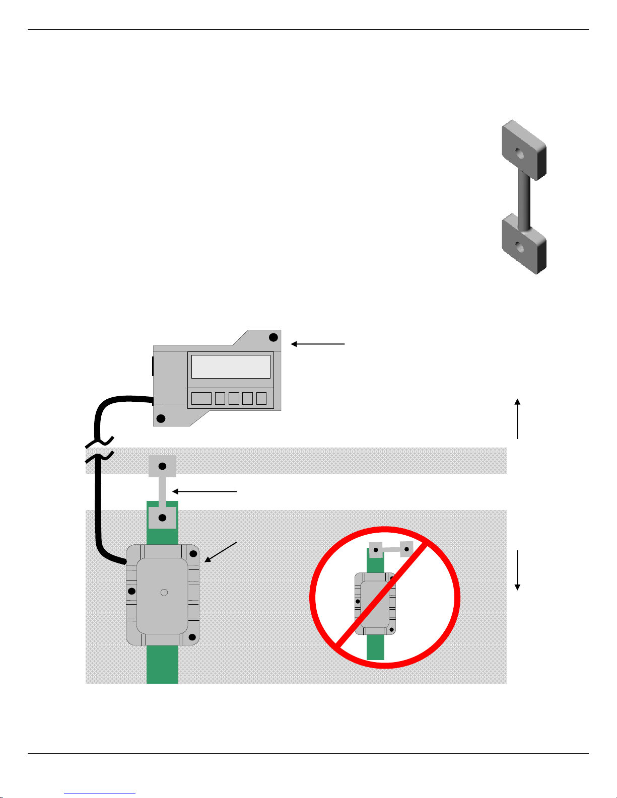
Installation:.................................................................................................................................................... 12
Calibration:.................................................................................................................................................... 15
Maintenance:................................................................................................................................................. 15
SECTION 4 DIGITAL DISPLAY.......................................................................................................................... 16
Display Power............................................................................................................................................ 16
Programming The Display.......................................................................................................................... 16
Position Display Units................................................................................................................................. 18
Measuring Modes....................................................................................................................................... 18
Offset Adjustment....................................................................................................................................... 19
Lock Mode ................................................................................................................................................. 19
Display Hold Mode..................................................................................................................................... 19
Position Monitor Mode................................................................................................................................ 20
Segment Offset Adjustment........................................................................................................................ 20
Sending position to SPC device ................................................................................................................. 21
Jumpers..................................................................................................................................................... 21
Changing the Batteries............................................................................................................................... 22
Mounting the Display.................................................................................................................................. 22
SECTION 5 MISCELLANEOUS .......................................................................................................................... 23
Scales........................................................................................................................................................ 23
Readheads................................................................................................................................................. 23
Frequently Asked Questions ...................................................................................................................... 24
Error Codes & Factory Service................................................................................................................... 25
Communicating With Other Equipment....................................................................................................... 25
Read Head Output ..................................................................................................................................... 25
Abbe Error.................................................................................................................................................. 27
Appendix A................................................................................................................................................. 28
SECTION 6 ACCESSORIES .............................................................................................................................. 31
ProMUX-3 ..................................................................................................................................................... 31
ProMUX-4, ProMUX-8................................................................................................................................... 32
Pro RF........................................................................................................................................................... 33