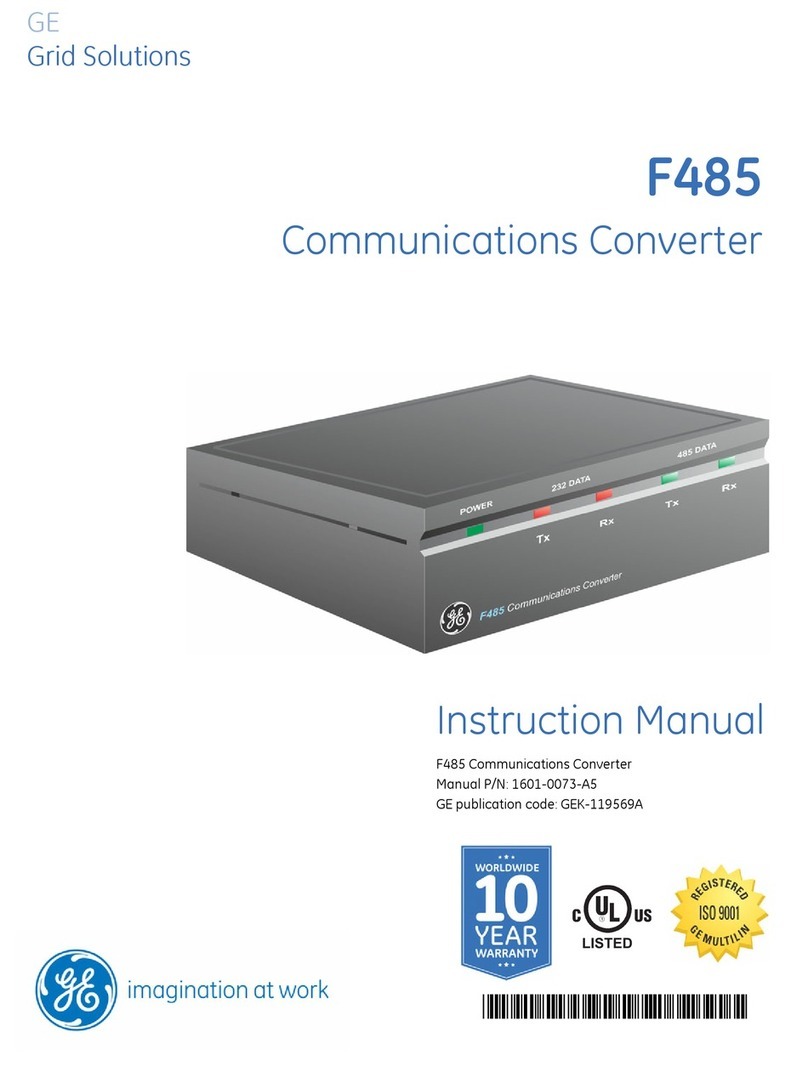
GE D485 User manual

D485 Modbus to DeviceNet
Converter
GE
Grid Solutions
*1601-0235-A2*
LISTED
Instruction Manual
GE publication code: 1601-0235-A2 (GEK-113195A)

Copyright © 2017 GE Multilin Inc. All rights reserved.
D485 Modbus to DeviceNet Converter Instruction Manual.
D485 is a registered trademark of GE Multilin Inc.
The contents of this manual are the property of GE Multilin Inc. This documentation is furnished on license and may not be
reproduced in whole or in part without the permission of GE Multilin Inc. The content of this manual is for informational use
only and is subject to change without notice.
Part numbers contained in this manual are subject to change without notice, and should therefore be verified by GE
Multilin Inc. before ordering.
Part number: 1601-0235-A2 (September 2017)

D485 MODBUS TO DEVICENET CONVERTER – USER GUIDE i
D485 Modbus to DeviceNet
Converter
Table of contents
GE
Grid Solutions
INTRODUCTION Getting started........................................................................................................1–1
Inspecting the package and product.................................................................................................1–1
Contact information...................................................................................................................................1–1
Document conventions..........................................................................................1–2
Description .....................................................................................................................................................1–2
Glossary...........................................................................................................................................................1–2
About the D485 Modbus to DeviceNet Converter.............................................1–3
Application......................................................................................................................................................1–3
Features....................................................................................................................1–3
General features..........................................................................................................................................1–3
Modbus network..........................................................................................................................................1–3
DeviceNet interface features.................................................................................................................1–3
Ordering ...................................................................................................................1–4
Order codes....................................................................................................................................................1–4
Specifications ..........................................................................................................1–4
Mechanical .....................................................................................................................................................1–4
Electrical characteristics..........................................................................................................................1–4
Communications .........................................................................................................................................1–4
Environmental...............................................................................................................................................1–4
EMC compliance ..........................................................................................................................................1–4
INSTALLATION Quick install .............................................................................................................2–1
Procedure........................................................................................................................................................2–1
Electrical installation .............................................................................................2–1
Overview..........................................................................................................................................................2–1
DeviceNet connector.................................................................................................................................2–2
Configuration cable....................................................................................................................................2–3
Modbus connector......................................................................................................................................2–4
Power connector .........................................................................................................................................2–4
Mechanical installation .........................................................................................2–5
DIN-rail mounting........................................................................................................................................2–5
Indicators and switches ........................................................................................2–5
Status indicators..........................................................................................................................................2–5
Configuration switches.............................................................................................................................2–6

ii D485 MODBUS TO DEVICENET CONVERTER – USER GUIDE
TABLE OF CONTENTS
DeviceNet installation procedure........................................................................2–7
DeviceNet configuration tool ................................................................................................................ 2–7
DeviceNet network termination...........................................................................................................2–7
Links ..................................................................................................................................................................2–7
Troubleshooting......................................................................................................2–8
Description.....................................................................................................................................................2–8
DATA EXCHANGE Overview...................................................................................................................3–1
Description.....................................................................................................................................................3–1
Internal memory buffer structure....................................................................................................... 3–2
I/O data vs. explicit data..........................................................................................................................3–3
Memory Map ............................................................................................................3–4
Memory locations.......................................................................................................................................3–4
Protocol configuration...........................................................................................3–5
Description.....................................................................................................................................................3–5
Communication mode..............................................................................................................................3–5
Protocol building blocks...........................................................................................................................3–5
DeviceNet object implementation.......................................................................3–6
Overview .........................................................................................................................................................3–6
Identity object (class 01h) .......................................................................................................................3–6
Message router (class 02h)..................................................................................................................... 3–7
DeviceNet object (class 03h).................................................................................................................. 3–7
Assembly object (class 04h)...................................................................................................................3–8
Connection object (class 05h) ...............................................................................................................3–8
Acknowledge handler object (class 2Bh) ...................................................................................... 3–10
I/O data input mapping object (class A0h)................................................................................... 3–11
I/O data output mapping object (class A1h) ............................................................................... 3–11
Diagnostic object (class AAh).............................................................................................................. 3–12
Parameter data input mapping object (class B0h) .................................................................. 3–12
Parameter data output mapping object (class B1h) ............................................................... 3–13
SOFTWARE
OVERVIEW
Introduction .............................................................................................................4–1
Description.....................................................................................................................................................4–1
System requirements................................................................................................................................4–1
Installation procedure ...........................................................................................4–1
Description.....................................................................................................................................................4–1
Installing from EnerVista CD..................................................................................................................4–1
Installing from the GE Multilin website.............................................................................................. 4–1
Using the EnerVista P485/D485 Setup software ...............................................4–2
Description.....................................................................................................................................................4–2
Configuration wizard................................................................................................................................. 4–2
Select fieldbus type....................................................................................................................................4–3
Sub-network properties ...........................................................................................................................4–4
Device types.................................................................................................................................................. 4–5
Connecting devices....................................................................................................................................4–7
Selecting parameters for each node.................................................................................................4–8
Configuration report..................................................................................................................................4–8
Configuration main window .................................................................................4–9
Description.....................................................................................................................................................4–9
Navigation window ................................................................................................................................. 4–10

Parameter window.................................................................................................................................. 4–10
Information window ............................................................................................................................... 4–10
Configuration line indicator ................................................................................................................ 4–10

TABLE OF CONTENTS
D485 MODBUS TO DEVICENET CONVERTER – USER GUIDE iii
Options window ........................................................................................................................................4–11
Fieldbus configuration........................................................................................ 4–11
Description ..................................................................................................................................................4–11
P485/D485 configuration ................................................................................... 4–12
Parameter window ..................................................................................................................................4–12
Modbus network configuration......................................................................... 4–13
Overview.......................................................................................................................................................4–13
Serial interface settings.........................................................................................................................4–13
COMMUNICATION
MODEL
Introduction.............................................................................................................5–1
Description .....................................................................................................................................................5–1
Scan list............................................................................................................................................................5–2
Basic settings ..........................................................................................................5–2
Network settings..........................................................................................................................................5–2
Communication............................................................................................................................................5–2
Message delimiter.......................................................................................................................................5–2
Nodes ........................................................................................................................5–3
Description .....................................................................................................................................................5–3
Node parameters ........................................................................................................................................5–3
Modbus network menu ............................................................................................................................5–3
Node menu.....................................................................................................................................................5–3
Query parameters ......................................................................................................................................5–4
Response parameters...............................................................................................................................5–5
FRAME AND
COMMAND EDITORS
Frame editor ............................................................................................................6–1
Description .....................................................................................................................................................6–1
Example ...........................................................................................................................................................6–1
Command editor .....................................................................................................6–2
General.............................................................................................................................................................6–2
Specifying a new command ..................................................................................................................6–3
MODBUS NETWORK
AND NODE
MONITORS
Modbus network monitor......................................................................................7–1
General.............................................................................................................................................................7–1
Operation ........................................................................................................................................................7–2
Node monitor...........................................................................................................7–3
General.............................................................................................................................................................7–3
Operation ........................................................................................................................................................7–3
ADVANCED
FUNCTIONS
Control and status registers.................................................................................8–1
Description .....................................................................................................................................................8–1
Control register (DeviceNet control system to D485).................................................................8–1
Control codes ................................................................................................................................................8–2
Status register (D485 to fieldbus control system)........................................................................8–2
Status codes ..................................................................................................................................................8–3
Handshaking procedure ..........................................................................................................................8–3
Input/output data during startup .......................................................................8–4
Description .....................................................................................................................................................8–4
Advanced fieldbus configuration.........................................................................8–5
Mailbox command......................................................................................................................................8–5
Parameter data input area mapping.................................................................................................8–5

iv D485 MODBUS TO DEVICENET CONVERTER – USER GUIDE
TABLE OF CONTENTS
Parameter data output area mapping............................................................................................. 8–7
I/O data input area mapping ................................................................................................................8–8
I/O data output area mapping .......................................................................................................... 8–10
APPLICATION
EXAMPLE
Introduction .............................................................................................................9–1
Overview .........................................................................................................................................................9–1
Equipment and documents....................................................................................................................9–1
System setup ................................................................................................................................................ 9–2
Modbus user map setup ........................................................................................9–3
Description.....................................................................................................................................................9–3
PQMII user map ........................................................................................................................................... 9–3
MM2 user map .............................................................................................................................................9–3
System configuration.............................................................................................9–5
Overview .........................................................................................................................................................9–5
Installing the EnerVista P485/D485 Setup software ..................................................................9–6
Starting the configuration wizard .......................................................................................................9–6
Step 1: Selecting the fieldbus type .....................................................................................................9–6
Step 2: Selecting the sub-network properties ...............................................................................9–7
Step 3: Include device types..................................................................................................................9–7
Step 4: Connect devices to the sub-network.................................................................................9–9
Step 5: Select parameters for each node..................................................................................... 9–10
Step 6: Configuration report ............................................................................................................... 9–11
Saving device data.................................................................................................................................. 9–12
Configuring the queries......................................................................................................................... 9–12
Grouping I/O data.................................................................................................................................... 9–15
I/O data Input mapping ........................................................................................................................ 9–15
Parameter data input area mapping ............................................................................................. 9–17
Downloading the configuration file................................................................................................. 9–18
DeviceNet network setup................................................................................... 9–19
Description.................................................................................................................................................. 9–19
Selecting the input attribute for polling and COS ..................................................................... 9–19
MISCELLANEOUS Revision history.................................................................................................... 10–1
Release dates............................................................................................................................................. 10–1
Changes to the manual ........................................................................................................................ 10–1
Warranty ............................................................................................................... 10–1
GE Multilin warranty statement........................................................................................................ 10–1
INDEX

D485 MODBUS TO DEVICENET CONVERTER – USER GUIDE 1–1
D485 Modbus to DeviceNet
Converter
Chapter 1: Introduction
GE
Grid Solutions
Introduction
Getting started
INSPECTING THE
PACKAGE AND PRODUCT
Examine the shipping container for obvious damage prior to installing this product; notify
the carrier of any damage that you believe occurred during shipment or delivery. Inspect
the contents of this package for any signs of damage and ensure that the items listed
below are included.
Remove the items from the shipping container. Be sure to keep the shipping container
should you need to re-ship the unit at a later date.
In the event there are items missing or damaged, contact the party from whom you
purchased the product. If the unit needs to be returned, please use the original shipping
container, if possible.
CONTACT INFORMATION For product support, contact the information and call center as follows:
GE Grid Solutions
650 Markland Street
Markham, Ontario
Canada L6C 0M1
Worldwide telephone: +1 905 927 7070
Europe/Middle East/Africa telephone: +34 94 485 88 54
North America toll-free: 1 800 547 8629
Fax: +1 905 927 5098
Website: http://www.gegridsolutions.com/multilin

1–2 D485 MODBUS TO DEVICENET CONVERTER – USER GUIDE
INTRODUCTION
Document conventions
DESCRIPTION The following conventions are used throughout this document:
• Numbered lists provide sequential steps.
• Bulleted lists provide information, not procedural steps.
• The term ‘user’ refers to the person or persons responsible for installing the D485
Modbus to DeviceNet Converter in a network.
• Hexadecimal values are written in the format 0xNNNN, where NNNN is the
hexadecimal value.
• Decimal values are represented as NNNN, where NNNN is the decimal value.
• As in all communication systems, the terms “input” and “output” can be ambiguous,
since their meaning depends on which end of the link is being referenced. The
convention in this document is that “input” and “output” are always being referenced
to the master/scanner end of the link (see illustration below).
• The term “sub-network” is interchangeably used for “Modbus network”.
Figure 1-1: Input and output definition
GLOSSARY The following terminology is used in the D485 manual:
• Broadcaster: A protocol specific node in the sub-network scan that holds transactions
destined for all nodes.
• Command: A protocol specific transaction.
• Fieldbus: The network to which the converter is connected (DeviceNet for D485).
• Frame: A higher level series of bytes forming a complete telegram on the sub-network
(Modbus).
• Monitor: A tool for debugging the D485 and network connections.
• Node: A device in the scan list that defines the communication with a slave (GE relay)
on the Modbus sub-network.
• Scan list: List of configured slaves with transactions on the sub-network.
• Sub-network: Modbus network that logically is located on a subsidiary level with
respect to the fieldbus and to which the D485 acts as a gateway.
• Transaction: A generic building block that is used in the sub-network scan list and
defines the data that is sent out the sub-network.
DeviceNet
master
Slave GE Multilin
D485 Converter Slave
Modbus
network
DeviceNet network
OUT
IN
OUT
IN

INTRODUCTION
D485 MODBUS TO DEVICENET CONVERTER – USER GUIDE 1–3
About the D485 Modbus to DeviceNet Converter
APPLICATION The D485 Modbus to DeviceNet Converter (or D485) acts as a gateway between the
Modbus protocol and a DeviceNet network. Integration of industrial devices is enabled
without loss of functionality, control, and reliability, both when retrofitting to existing
equipment as well as when setting up new installations.
Figure 1-2: Typical applications
Features
GENERAL FEATURES • DIN-rail mountable
• Save/load configuration in flash
•CE,UL,andcULmarked
MODBUS NETWORK • RS232/RS422/RS485 communications
• Multi-drop or single-node configurations possible
• Modbus RTU Master mode
• Supports up to 50 commands
• Configuration via EnerVista P485/D485 Setup software
DEVICENET INTERFACE
FEATURES
• Complete DeviceNet adapter functionality (profile no. 12 group 2 only server)
• Group two only server
• MAC ID and baud rate configuration via on-board switches
• Polled, Change of State (COS), and Bit Strobed I/O
• Explicit messaging
DeviceNet
master (PLC)
HMI
DeviceNet
slave
DeviceNet network
D485
PC for configuration
and monitoring
Multi-drop
Multi-node Modbus network
Single-node Modbus network
RS232 port
PC for configuration
and monitoring
DeviceNet slave
HMI
DeviceNet
master (PLC)
DeviceNet network
D485

1–4 D485 MODBUS TO DEVICENET CONVERTER – USER GUIDE
INTRODUCTION
Ordering
ORDER CODES The following table illustrates the order codes for the D485 Modbus to DeviceNet
Converter.
Specifications
MECHANICAL HOUSING
Plastic housing with snap-on connection to DIN-rail, protection class IP20
DIMENSIONS
L x W x H: 120 mm ×75 mm ×27 mm
(4.72-in ×2.95-in ×1.06-in)
PROTECTION CLASS
Protection class: IP20
ELECTRICAL
CHARACTERISTICS
POWER SUPPLY
Power: 24 V ±10% (for use in class 2 circuits)
POWER CONSUMPTION
Maximum power consumption: 280 mA on 24 V
Typically power consumption: approximately 100 mA
COMMUNICATIONS BAUD RATES
Baud rate (DeviceNet) 125, 250, and 500 kbps
Baud rate (Modbus) 1200, 2400, 4800, 9600, 19200, 38400, and 57600 bps
I/O DATA
I/O input size: 512 bytes
I/O output size: 512 bytes
FEATURES AND INTERFACE
Supported features: bit strobe, polling, cyclic and COS I/O messaging, explicit messaging
Modbus interface: RS232, RS422, RS485
DeviceNet interface: 5-pin linear DeviceNet plug (Phoenix type)
ENVIRONMENTAL RELATIVE HUMIDITY
The product is designed for a relative humidity of 0 to 95% non-condensing
TEMPERATURE
Operating: 0 to 55°C
Non Operating: –5 to 85°C
EMC COMPLIANCE CE-MARK
Certified according to European standards unless otherwise is stated
Emission: according to EN 50081-2:1993
Immunity: according to EN 61000-6-2:1999
UL/C-UL COMPLIANCE
This unit is an open type listed by the Underwriters Laboratories.
The certification has been documented by UL in file E214107.
Table 1–1: D485 order codes
D485 – *
Base unit D485 |D485 Modbus to DeviceNet Converter
CWith configuration cable
XNo configuration cable

D485 MODBUS TO DEVICENET CONVERTER – USER GUIDE 2–1
D485 Modbus to DeviceNet
Converter
Chapter 2: Installation
GE
Grid Solutions
Instal lati on
Quick install
PROCEDURE 1. Snap the D485 on to the DIN-rail (see DIN-rail mounting on page 2–5).
2. Connect the DeviceNet cable (see DeviceNet connector on page 2–2).
3. Connect the serial Modbus network cable (see Modbus connector on page 2–4 for
details).
4. Connect a PC using the configuration cable (see Configuration cable on page 2–3).
5. Connect the power cable and apply power to the unit (see Power connector on page
2–4 for details).
6. Start the EnerVista P485/D485 Setup software.
7. Normally, the EnerVista P485/D485 Setup detects the correct serial port. If this does
not occur, select the correct port through the Port menu item.
8. Configure the D485 using EnerVista P485/D485 Setup and download the
configuration to the unit.
9. Configure and power-up the Modbus network device for communication.
Electrical installation
OVERVIEW The location of the various electrical connectors is shown below.

2–2 D485 MODBUS TO DEVICENET CONVERTER – USER GUIDE
INSTALLATION
Figure 2-1: D485 electrical connections
DEVICENET CONNECTOR The DeviceNet connector is indicated as Ain the figure above. This connector is used to
connect the D485 to the DeviceNet network.
The pin assignments for the DeviceNet connector are shown below.
Figure 2-2: DeviceNet connector
E
A
B
C
D
Table 2–1: DeviceNet connector pin assignments
Pin Signal Description
1 V– DeviceNet bus power, negative supply voltage
2 CAN L CAN L bus line
3 Shield Cable shield
4 CAN H CAN H bus line
5 V+ DeviceNet bus power, positive supply voltage
15

INSTALLATION
D485 MODBUS TO DEVICENET CONVERTER – USER GUIDE 2–3
CONFIGURATION CABLE The PC connector is indicated as Bin Figure 2-1: D485 electrical connections on page 2–2.
This connector is used to connect the D485 to a PC using the configuration cable for
configuration and monitoring purposes.
A configuration cable can be purchased from GE Multilin. The wiring for the configuration
cable is shown below.
Figure 2-3: Configuration cable
The pinout for the modular 4/4 RJ11 connector (connects to the D485) is shown below.
Figure 2-4: Configuration cable (D485 end)
The pinout for the DSUB 9-pin serial plug (connects to the PC) is shown below.
Table 2–2: Configuration cable pin assignments (D485 end)
Pin Description
1 Signal ground
2 Signal ground
3 RS232 Rx, data input to D485
4 RS232 Tx, data output from D485
Table 2–3: Configuration cable pin assignments (PC end)
Pin Description
1 Not connected
2 RS232 Rx, data input to PC
3 RS232 Tx, data output from PC
4 Not connected
5 Ground
6 to 9 Not connected
1
2
3
4
5
6
7
8
9
1
2
3
4
D-sub 9 female (PC) Modular 4/4 RJ11 connector (D485)
Ground
Ground
Rx
Tx
RS232 Tx
RS232 Rx
Ground
Connects to PC serial port
Connects to D485
1
2
3
4

2–4 D485 MODBUS TO DEVICENET CONVERTER – USER GUIDE
INSTALLATION
Figure 2-5: Configuration cable (PC end)
MODBUS CONNECTOR The Modbus connector is indicated as Cin Figure 2-1: D485 electrical connections on page
2–2. This connector is used to connect the D485 to the serial network. Based on the
configuration selected in the EnerVista P485/D485 Setup software, the corresponding
signals are activated.
Figure 2-6: Modbus connector
POWER CONNECTOR The power connector is indicated as Din Figure 2-1: D485 electrical connections on page
2–2. Use this connector to apply power to the D485.
Pin 1: +24 V DC;
Pin 2: ground
Use 60/75 or 75°C copper (CU) wire only. The terminal tightening torque must be between
5 to 7 lbs-in (0.5 to 0.8 nm).
Figure 2-7: Power connector
51
69
(female)
Table 2–4: Modbus connector pin assignments
Pin Description RS232 RS422 RS485
1 +5Voutput(50mAmax)
2 RS232 Rx
3 RS232 Tx
4 Not connected
5 Ground
6 RS422 Rx +
7 RS422 Rx –
8 RS485 + / RS422 Tx+
9 RS485 – / RS422 Tx–
51
69
(female)
NOTE
12

INSTALLATION
D485 MODBUS TO DEVICENET CONVERTER – USER GUIDE 2–5
Mechanical installation
DIN-RAIL MOUNTING The DIN-rail connector is internally connected to the D485.
Figure 2-8: Mounting the D485 to the DIN-rail
To snap the D485 on, first press the D485 downwards (1) to compress the spring on the
DIN-rail connector, then push the D485 against the DIN-rail as to make it snap on (2)
To snap the D485 off, push the D485 downwards (1) and pull it out from the DIN-rail (2), as
to make it snap off from the DIN-rail.
Indicators and switches
STATUS INDICATORS The status indicators for the D485 Modbus to DeviceNet Converter are indicated below.
Figure 2-9: D485 status indicators
11
22
ON OFF
1
3
5
2
4
6

2–6 D485 MODBUS TO DEVICENET CONVERTER – USER GUIDE
INSTALLATION
CONFIGURATION
SWITCHES
The configuration switches are used to set the DeviceNet MAC ID and baud rate settings.
Normally, these switches are covered by a plastic hatch. Note that the node address can
not be changed during runtime, i.e. the D485 requires a reset for any changes to have
effect. Recycle the power supply to reset the module.
Figure 2-10: D485 configuration switches
Table 2–5: D485 status indicators
Number Description State Status
1 Network status Off Not powered / not online
Green Link OK, online, connected
Green flashing Online, not connected
Red Critical link failure
Red flashing Connection timeout
2 Module status Off No power to device
Green Device operational
Green flashing Data size larger than configured
Red Unrecoverable fault
Red flashing Minor fault
3Notused- -
4Notused- -
5 Modbus
status *
Off Power off
Green, flashing Initializing and not running
Green Running
Red Stopped or subnet error, or timeout
6 Device status Off Power off
Red/green
alternating
Invalid or missing configuration
Green Initializing
Green flashing Running
Red flashing If the device status LED is flashing in a
sequence starting with one or more red
flashes, note the sequence pattern and
contact GE Multilin
* This LED turns green when all transactions have been active at least once. This includes any
transactions using “change of state” or “change of state on trigger”. If a timeout occurs on a
transaction, this LED will turn red.
8
7
6
5
4
3
2
1

INSTALLATION
D485 MODBUS TO DEVICENET CONVERTER – USER GUIDE 2–7
The DeviceNet MAC ID and baud rate switches are set according to the following tables.
When removing the hatch, avoid touching the circuit boards and components. Exercise
caution when using tools to open the hatch.
DeviceNet installation procedure
DEVICENET
CONFIGURATION TOOL
Each device on a DeviceNet network is associated with a ESD file, which contains all
necessary information about the device. This file is used by the DeviceNet configuration
tool during configuration of the network. The file is available for download at the GE
Multilin website at http://www.GEmultilin.com (the ESD file is named ‘D485.ESD’).
It is necessary to import the ESD file in the DeviceNet configuration tool in order to
incorporate the D485 as a slave in the DeviceNet network. The properties for the D485
must then be configured from the DeviceNet configuration tool. This includes setting up
the node address, input/output data areas and DeviceNet baud rate.
•Node address: The node address in the DeviceNet configuration tool should be set to
match the one selected using the on board configuration switches of the D485 (see
Configuration switches on page 2–6).
•Setting up input/output data areas: To establish the connection with the master, the
D485 mus be configured for correct I/O sizes.
•Baud rate: The DeviceNet network baud rate should match the D485 baud rate
setting.
DEVICENET NETWORK
TERMINATION
If the D485 is the last node on a DeviceNet network, it is necessary to use a DeviceNet
network termination resistor of 120 ohms between the CAN L and CAN H terminals.
LINKS Additional information about the DeviceNet fieldbus system can be found at http://
www.odva.org.
Table 2–6: Baud rate settings
Baud rate Switch 1 Switch 2
125 kbps OFF OFF
250 kbps OFF ON
500 kbps ON OFF
Reserved ON ON
Table 2–7: MAC ID settings
MAC ID Switch 3 Switch 4 Switch 5 Switch 6 Switch 7 Switch 8
0 OFF OFF OFF OFF OFF OFF
1 OFF OFF OFF OFF OFF ON
2 OFF OFF OFF OFF ON OFF
3 OFF OFF OFF OFF ON ON
↓ ↓↓↓↓↓↓
63 ON ON ON ON ON ON
NOTE

2–8 D485 MODBUS TO DEVICENET CONVERTER – USER GUIDE
INSTALLATION
Troubleshooting
DESCRIPTION Problem during configuration upload/download. The Config Line LED turns red.
• Serial communication failed – try again.
The serial port seems to be available, but it is not possible to connect to the D485.
• The serial port may be in use by another application. Exit EnerVista P485/D485 Setup
and close all other applications including the ones in the system tray and try again.
• Select another serial port and try again.
Poor performance.
• Right click ‘Modbus Network’ in the Navigation window and select ‘Modbus Network
Status’ to see status/diagnostic information about the sub network. If the D485
reports very many retransmissions, check your cabling and/or try a lower baud rate
setting for the sub network (if possible).
• Is the Modbus Network Monitor in EnerVista P485/D485 Setup active? The Modbus
network monitor has a negative influence on the overall performance of the D485,
and should only be used when necessary.
• Is the Node Monitor in EnerVista P485/D485 Setup active? The node monitor has a
negative influence on the overall performance of the D485, and should only be used
when necessary.

D485 MODBUS TO DEVICENET CONVERTER – USER GUIDE 3–1
D485 Modbus to DeviceNet
Converter
Chapter 3: Data Exchange
GE
Grid Solutions
Data Exchang e
Overview
DESCRIPTION Data from the fieldbus (DeviceNet) and the sub network (Modbus) is stored in an internal
memory buffer. This is a easy method for data exchange where the fieldbus control
system simply reads and writes data to pre-defined memory locations, and the serial sub
network also use the same internal memory buffer to read and write data.
Refer to Figure 3-1: Data exchange overview on page 3–2 for additional details.

3–2 D485 MODBUS TO DEVICENET CONVERTER – USER GUIDE
DATA EXCHANGE
Figure 3-1: Data exchange overview
INTERNAL MEMORY
BUFFER STRUCTURE
The internal memory buffer can be seen as a memory space with three different types of
data; input data, output data and general data.
•Input data: This is data that should be sent to the fieldbus. The D485 can handle up to
512 bytes of input data.
•Output data: this is data recieved from the fieldbus. The D485 can handle up to 512
bytes of output data.
•General data: This data cannot be accessed from the fieldbus, and is used for
transfers between nodes on the sub-network, or as a general “scratch pad” for data.
The D485 can handle up to 1024 bytes of general data.
The PLC exchanges data
via the DeviceNet network
between its internal input
area and the input area
of the D485 DeviceNet network
The PLC exchanges data
via the network
between its internal output
area and the output area
of the D485
DeviceNet
The data in the input area of
the D485 contains data received
from nodes on the Modbus
sub-network (sent in to the D485
from the sub-network)
The data in the output area of the
D485 contains data received from
In this case, it is the CT PRIMARY
setting of the PQMII meter
(sent out from the D485 to the sub-network).
DeviceNet
0x0000 0x0200 0x0400
Input data area Output data area General data area
Modbus sub-network
Current Ia CT PRIMARY
Internal memory buffer
of the D485
PLC memory
I/O inputs I/O outputs
Current Ia CT PRIMARY
Modbus slave (e.g. PQMII)
CT PRIMARY setting
Current Ia actual value
Table of contents
Other GE Media Converter manuals

GE
GE GEH-6294 User manual

GE
GE iSTAT I4 Series User manual

GE
GE RAP02 User manual

GE
GE P485 User manual

GE
GE 6KCV300CTI User manual

GE
GE J2007003L064 User manual

GE
GE MultiNet User manual

GE
GE Multilin F485 User manual

GE
GE Video Converter RF Modulator with S-Video User manual

GE
GE AF-650 GP PROFINET User manual