IMKO TRIME-PICO 64 User manual
Manual
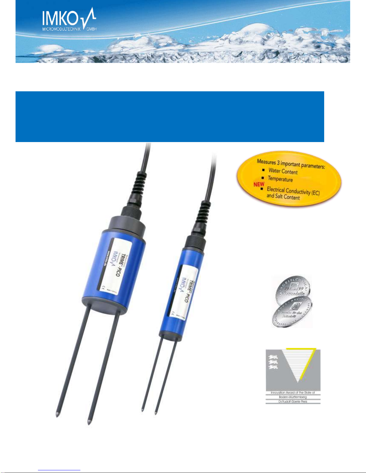
TRIME-PICO 64/32

Manual TRIME_PICO64-32 Version 2_0 2017-05-30
Page 2
Thank you for purchasing a IMKO instrument.
Should you have any queries please
don’t hesitate to contact your local
distributor or address directly to IMKO:
IMKO Micromodultechnik GmbH
Am Reutgraben 2
D-76275 Ettlingen
Germany
Phone: +49-7243-5921-0
Fax: +49-7243-90856
Internet: http://www.imko.de

2017-05-30 Manual TRIME_PICO64-32 Version 2_0
Page 3
Manual for TRIME®-PICO 64/32
List of Contents
1Functional Description .................................................................................................... 5
1.1 Operation modes ........................................................................................................ 5
1.1.1 Operation mode A (Bus communication) .................................................................5
1.1.2 Operation mode B (Single measurement) ................................................................6
1.1.3 Operation mode C (Cyclic measurement)................................................................. 6
1.1.4 PC connection.......................................................................................................6
1.2 External power supply..................................................................................................6
2Technical Data................................................................................................................ 7
2.1 TRIME-PICO64.............................................................................................................7
2.2 TRIME-PICO32.............................................................................................................7
2.3 Installation hints..........................................................................................................8
3TRIME-PICO64/32 Versions:.............................................................................................9
3.1 PICO DataLogger cable 5m with end splices (Item no.: 300082) ...................................... 10
3.2 PICO IMP-Bus cable 5m, 4-pin female connector (Item no.: 300080) ............................... 10
3.3 PICO BT+TRIME-HD cable 1,5m, 7-pin female connector (Item no.:300081) ..................... 10
3.4 Accessories...............................................................................................................11
3.4.1 E-Box (Extension Box), (Item no.: 300092).............................................................. 11
3.4.2 C-Box (Current Box), (Item no.: 300091) ................................................................ 11
3.4.3 SM-USB Serial Interface Module ..........................................................................12
3.4.4 PICO-BT Bluetooth Module .................................................................................. 12
3.5 Datalogging with Differential Analog Inputs..................................................................13
4Installation details: ....................................................................................................... 14
4.1 Temperature measurement:....................................................................................... 14
4.2 Installation equipment:..............................................................................................14
4.2.1 Preparation set for TRIME-PICO64, (Item no.: 302035) ............................................14
4.2.2 Preparation set for TRIME-PICO32, (Item no.: 302023) ............................................14
4.2.3 Extension tubes for TRIME-PICO64 & TRIME-PICO32............................................... 15
4.2.4 Hand Auger Set for TRIME-PICO64 & TRIME-PICO32 ...............................................15
5Remote Power Supply to TRIME-PICO ............................................................................ 16
6Basic Calibration with the Calibration Set ....................................................................... 17
6.1 What is a basic calibration? ........................................................................................ 17
6.2 What are the benefits of the calibration set for the user? .............................................. 17
6.2.1 Calibration set for TRIME probes...........................................................................17
6.3 How to perform a basic calibration? ............................................................................17

Manual TRIME_PICO64-32 Version 2_0 2017-05-30
Page 4
6.3.1 Preparation of the glass beads..............................................................................17
6.3.2 Basic calibration procedure ..................................................................................18
7Material-Specific Calibration..........................................................................................19
7.1 Soil Density Correction with PICO Sensors ....................................................................19
8Mounting Spare Rods with O-ring Seals ..........................................................................21
9Information on Lightning Protection of the ENVIS Environmental Measurement System....22
9.1 Introduction..............................................................................................................22
9.2 Excess voltage protection on 110/220V mains supply ....................................................22
9.3 Protection of modem and telephone lines....................................................................22
9.4 Excess voltage protection for network modules by "SM-Blitz".........................................22
9.5 Lightning protection on meteorological towers.............................................................22
9.6 Installation instructions for SM BLITZ lightning protection modules.................................22
9.7 Conclusion................................................................................................................22
10 Datalogging configuration examples...............................................................................23
10.1 PICO probes connected to a PC under Windows............................................................23
10.2 PICO probes connected to a SDI12 Datalogger ..............................................................24
11 Quick guide for the Software PICO-CONFIG.....................................................................25
11.1 Connection of the RS485 or the SDI-12 and the IMP-Bus to the SM-USB Module ..............25
11.1.1 RS485 or IMP-Bus Configuration and Probe Scan ....................................................26
11.2 Scan of connected PICO probes on the RS485 or IMP-Bus ..............................................27
11.3 Configuration of Measure Mode .................................................................................27
11.4 Analogue outputs of the PICO probe............................................................................28
11.5 Simulate Analog Output .............................................................................................28
11.6 Selection of the individual Calibration Curves ...............................................................29
11.7 Test Run in Measurement Mode A ..............................................................................30
11.8 TRIME WIN MONITOR Datalogger Software..................................................................31
11.9 Calibration Curves .....................................................................................................32
11.10 Creating a linear Calibration Curve for a specific Material...............................................35
11.10.1 Calculation for a linear 2-point calibration curve.....................................................35
11.10.2 Calculation for a non-linear calibration curve .........................................................36
12 Measure Electrical Conductivity with TRIME Probes.........................................................37
12.1 The analysis of Soils for Electrical Conductivity ECTRIME ...................................................38
12.2 ECTRIME Measurement Range for TRIME Probes.............................................................39
12.3 Measurement of Pore-Water-Conductivity or Salt-Content of Soils .................................39
12.4 Creation of a Moisture/ ECTRIME Diagram for a particular Soil..........................................42
13 Software Error codes.....................................................................................................43
13.1 Software Errors which will be coded with 4 digits. ........................................................43
13.2 PICO Errors (Firmware errors). The errors come from the firmware, from 1 to 255. ..........44
14 Savety Notes ................................................................................................................45

2017-05-30 Manual TRIME_PICO64-32 Version 2_0
Page 5
1Functional Description
The intelligent and compact TRIME-PICO64/32 sensors are measurement devices for continuous and non-
destructive determination of volumetric or gravimetric material moisture, material temperature and material
conductivity. They are designed for stationary subterranean field use. A variety of installation options (greater
depth, vertical or horizontal orientation) offer a wide range of applications.
TRIME-PICO64/32 systems require an external 7-24V/DC power supply. They are designed for connection to a
data logger or a PC for monitoring and data logging purposes.
Your sensor is supplied ready for use and works in a wide range of standard soils. For further information
please check the details under Section 6!
1.1 Operation modes
TRIME-PICO64/32 systems are supplied with an IMP-Bus interface and analogue output of 0..1V for soil mois-
ture and temperature.
TRIME-PICO64/32 sensors can be easily connected (in operation modes A) to SDI12 datalogger and conven-
tional analogue data loggers (in operation modes B and C).
A detailed description of how to select a specific operation mode for your application can be found below.
PLEASE NOTE: Analogue dataloggers require differential inputs!
1.1.1 Operation mode A (Bus communication)
TRIME-PICO64/32 systems can be connected directly to the IMP-Bus (4-wire bus system), either via SDI12 data-
logger or via the SM-23U level converter module for use in conjunction with the EnvisLog data-logging soft-
ware.
If multiple sensors are to be wired as a network, IMKO offers 3-port, 6-port and 12-port distribution modules.
Please note that the IMP-Bus cable length and cable diameter must be properly matched as otherwise the
energy consumption of the TRIME sensors (100mA @ 12V/DC for 2..3s) may cause a drop in voltage. More
information is available in Section 5.
Benefits:
Low power consumption in field installations (with SDI12 datalogger)
Straightforward installation and simple wiring by virtue of pre-configured standard compo-
nents (e.g. lightning protection, distribution modules…)
Attachment of any other analogue sensors to IMP-Bus (via SM-Modules)
Systems are supplied ready for use
Cable length >1000m (with only 4 wires for all sensors)
For use with:
SDI12 Datalogger
EnvisLog (PC-Software for Microsoft Windows) only with converter module SM-USB
IMKO calibration and test software PICO-CONFIG (see page 27, Software download:
www.imko.de) only with converter module SM-USB
This manual suits for next models
1
Table of contents
Other IMKO Accessories manuals


