IMKO TRIME-PICO T3/IPH44 User manual
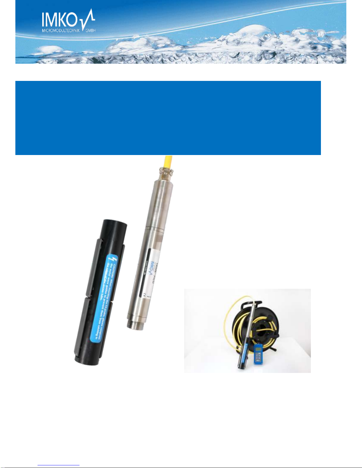
TRIME-PICO T3/IPH44 TRIME-PICO T3/IPH50 Complete Set
Tube Access Probe Head
and TDR-Electronic Head
User Manual
TRIME®-PICO T3/IPH44
and T3/IPH50

TRIME®-PICO T3/IPH44 IPH50 Version 2_0 2017-05-30
Page 2
Thank you very much for deciding to
purchase this IMKO product!.
Should you have any queries please
contact your local distributor or address
directly to IMKO:
IMKO Micromodultechnik GmbH
Am Reutgraben 2
D-76275 Ettlingen
Germany
Phone: +49-7243-5921-0
Fax: +49-7243-90856
Internet: http://www.imko.de

2017-05-30 TRIME®-PICO IPH Version 2_0
Page 3
Manual for TRIME®-PICO IPH
List of contents
1Functional Description TRIME-PICO IPH..........................................................5
1.1 Operation modes ...........................................................................................5
1.1.1 Operation mode A (Protocol communication) .......................................5
1.1.2 Operation mode B (Single measurement) ..............................................5
1.1.3 Operation mode C (Cyclic measurement) ..............................................6
1.2 External power supply...................................................................................6
1.3 Installation hints .............................................................................................6
2Technical Data ...................................................................................................7
2.1 TRIME-PICO T3/IPH44 ...................................................................................7
3TRIME-PICO IPH Versions: ................................................................................9
3.1 TRIME-PICO IPH cable 3.5m, 7-pin female connector.................................9
4Accessories ......................................................................................................10
4.1 PICO-BT, (Item no.: 300090) .......................................................................10
4.2 SM-USB (Converter Module), (Item no.: 100020) ......................................10
4.3 Extension cable, (Item no.: 300049) ...........................................................11
4.4 Analog extension cable, (Item no.: 300102) ..............................................11
5Installation details: ..........................................................................................12
5.1 General suggestions: ...................................................................................12
5.2 Installation equipment:................................................................................12
5.2.1 Auger equipment for ø44mm TECANAT tubes ...................................12
5.2.2 Soil anchor set for auger equipment, ...................................................13
5.2.3 TECANAT access tube 1m / ø44mm.....................................................13
5.2.4 TECANAT access tube 2m / ø44mm.....................................................13
5.2.5 TECANAT access tube 3m / ø44mm.....................................................13
6Remote Power Supply to TRIME-PICO IPH....................................................14
7The TRIME-PICO IPH Tube Access Probe ......................................................16
7.1 Introduction..................................................................................................16
7.2 Measuring Field............................................................................................16
7.3 Measuring experiences................................................................................18
7.4 Summary.......................................................................................................19
8Access Tubes and Augers ...............................................................................20

TRIME®-PICO T3/IPH44 IPH50 Version 2_0 2017-05-30
Page 4
9Instructions for Access Tube Installation ....................................................... 22
9.1 Inserting and Fixing the Rubber Bung ....................................................... 23
10 TRIME-PICO T3/IPH50 .................................................................................... 25
11 Basic Calibration with the Calibration Set..................................................... 26
11.1 What is a basic calibration? ........................................................................ 26
11.2 What are the benefits of the calibration set for the user? ....................... 26
11.2.1 Calibration set for TRIME probes......................................................... 26
11.3 How to perform basic calibration?............................................................. 26
11.3.1 Preparation of the glass beads............................................................. 26
11.3.2 Basic calibration procedure .................................................................. 27
12 Soil Density Correction with PICO Sensors................................................... 29
13 Material-Specific Calibration .......................................................................... 31
14 EMV/EMI Protection ....................................................................................... 32
15 Information on Lightning Protection of the ENVIS Environmental
Measurement System
(IMP-Bus, GlobeLog Logger and integrated Sensors)
32
15.1 Introduction ................................................................................................. 32
15.2 Excess voltage protection on 110/220V mains supply ............................. 32
15.3 Protection of modem and telephone lines ................................................ 32
15.4 Excess voltage protection for network modules by "SM-Blitz"............... 32
15.5 Lightning protection on meteorological towers ....................................... 32
15.6 Installation instructions for SM BLITZ lightning protection modules....... 33
15.7 Conclusion.................................................................................................... 33
16 Configuration example................................................................................... 34
16.1 TRIME-PICO IPH with PICO-BT module ..................................................... 34
16.2 TRIME-PICO IPH with HD2.......................................................................... 34
16.3 TRIME-PICO IPH with SM-USB.................................................................... 35
17 Error Codes ..................................................................................................... 36
17.1 TRIMETOOL Errors (Software errors),which will be coded with 4 digits36
17.2 PICO Errors (Firmware errors). The errors come from the firmware, from
1 to 255................................................................................................................. 37
18 Savety Notes ................................................................................................... 39

2017-05-30 TRIME®-PICO IPH Version 2_0
Page 5
1Functional Description TRIME-PICO IPH
The intelligent and compact TRIME-PICO IPH sensor is a measurement device for portable and
non-destructive determination of volumetric soil moisture in a profile. This system is designed
for portable field use. A variety of installation options (tubes are available in 1m, 2m and 3m)
offer a wide range of applications.
TRIME-PICO IPH can be used in different system configurations with either our display unit
TRIME-HD to display the soil moisture value in the field. Alternatively it can be used together
with a PDA (with the software PICO-Talk) in combination with the PICO-BT Bluetooth module.
This system offers the ability to store the measurements and to handle different sites, sensors
and depth. Also you are rid of annoying cables.
Your sensor is supplied ready for use and works in a wide range of standard soils. For further
information please check the details under Section 6!
1.1 Operation modes
The TRIME-PICO IPH is supplied with an RS485 interface and analogue output of 0..1V for soil
moisture.
The TRIME-PICO IPH can be easily connected to:
-PICO-BT Bluetooth module
-TRIME-HD analog display unit
-GlobeLog (special application in Version IMP-Bus)
-Analog-Loggers (special application)
A detailed description of how to select a specific operation mode for your application can be
found below.
PLEASE NOTE: Analogue dataloggers require differential inputs!
1.1.1 Operation mode A (Protocol communication)
In the standard version the TRIME-PICO IPH will be delivered with RS485-Interface, as it’s re-
quired for the use with the PICO-BT Bluetooth module. If the TRIME-PICO IPH should be con-
nected to the GlobeLog a special version with IMP-Bus has to be ordered.
If multiple sensors are to be wired as a network, IMKO offers 3-port, 6-port and 12-port distri-
bution modules (only for IMP-Bus). Please note that the RS485/IMP-Bus cable length and cable
diameter must be properly matched as otherwise the energy consumption of the TRIME sensors
(100mA @ 12V/DC for 2..3s) may cause a drop in voltage.
More information is available in Sec-
tion 5.
For use with:
PICO-BT Bluetooth module
IMKO calibration and test software TRIME-Tool (see www.imko.de) with convert-
er module SM-USB or PICO-BT module
GlobeLogger (Special version with IMP-Bus)
EnvisLog (PC-Software for Microsoft Windows) only with converter module SM-
USB
1.1.2 Operation mode B (Single measurement)
The TRIME-PICO IPH will perform a single measurement when the power is switched on. Once
the measurement has been taken (2..3s) the readings are supplied as analogue output signals

TRIME®-PICO T3/IPH44 IPH50 Version 2_0 2017-05-30
Page 6
until the power is switched off. The probe switches to the energy-saving mode (>1mA) and
takes no more measurements until the power has been switched off.
For use with:
TRIME-HD analog display module
Analogue data loggers with relay (Special application)
PC A/D converter boards with relay (Special application)
1.1.3 Operation mode C (Cyclic measurement)
TRIME-PICO IPH takes measurements at a freely configurable measurement rate (from 8s..24h).
Once the measurements have been taken (2..3s) the measured values are supplied as analogue
output signals. Until the next measurement is finished, the values of the previous measurement
are available as analogue signal. In standby until the next measurement is executed the probe
consumes 8..10mA @ 12V/DC.
For use with:
Mains power (Special application)
Analogue data loggers with mains power (Special application)
PC A/D converter boards (Special application)
1.2 External power supply
The TRIME-PICO IPH does not contain any kind of power supply, so that it has to be supplied
externally. At the portable systems PICO-BT and TRIME-HD this power will be provided by an
internally rechargeable battery.
If the TRIME-PICO IPH is used with the GlobeLogger it will be supplied by the IMP-Bus.
For the use with other stationary systems it has to be ensured, that the TRIME-PICO IPH will be
supplied by an external source with 7..24V/DC.
1.3 Installation hints
Please assure careful installation of the probes with close contact between tube and soil. It is
important to avoid air pockets around the tubes as the highest measuring sensitivity is directly
around them.
Air pockets around the tube wall can reduce the measured moisture reading. Where saturated
soils are involved, water-filled air pockets will result in an exaggerated reading.
IMKO supplies drilling equipment for an optimal preparation of the installation point, avoiding
air gaps around the tube and compaction of soil.
2017-05-30 TRIME®-PICO IPH Version 2_0
Page 7
2Technical Data
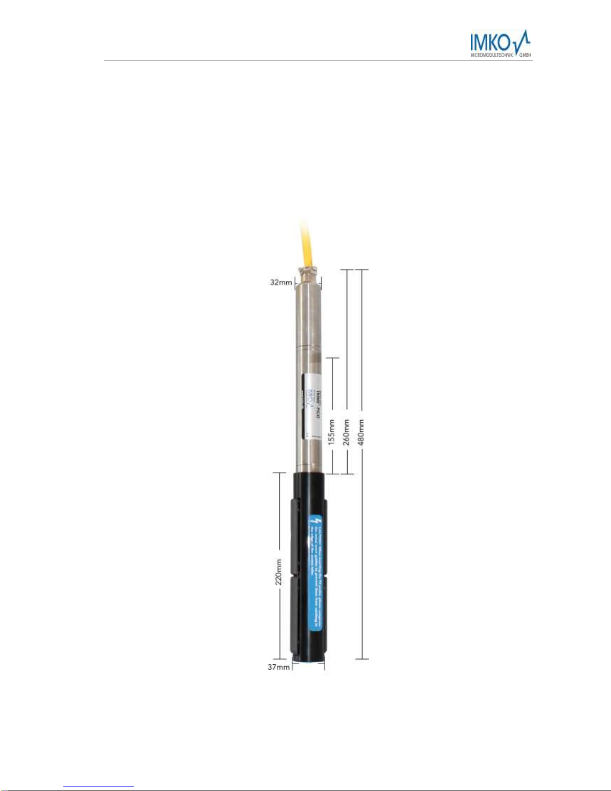
2.1 TRIME-PICO T3/IPH44
For in situ monitoring of volumetric moisture in soils. The large measuring volume is particularly
suitable for applications in heterogeneous and skeletal media. Burying capability for both hori-
zontal and vertical orientation.

TRIME®-PICO T3/IPH44 IPH50 Version 2_0 2017-05-30
Page 8
2017-05-30 TRIME®-PICO IPH Version 2_0
Page 9
3 TRIME-PICO IPH Versions:
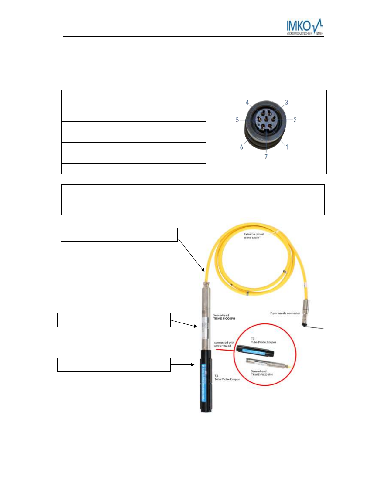
3.1 TRIME-PICO IPH cable 3.5m, 7-pin female connector
Pin layout:
Pin 1:
+Vs
Pin 2:
RS485-B
Pin 3:
GND
Pin 4:
RS485-A
Pin 5:
Not connected
Pin 6:
Not connected
Pin 7:
Not connected
List of abbreviations:
+Vs: + Voltage supply (7..24V/DC)
GND: Ground (for voltage supply)
AGND: Analogue ground
Spare cable, (Item no.: 980174)
Sensor Head (Item no.: 300045)
Corpus (Item no.: 303001)

TRIME®-PICO T3/IPH44 IPH50 Version 2_0 2017-05-30
Page 10
4 Accessories
4.1 PICO-BT, (Item no.: 300090)
For connecting the TRIME-PICO with PICO BT+TRIME-HD cable (see 3.1) to a PDA/PC via Blue-
tooth interface. Module contains a internal rechargeable battery, which enables >1000 meas-
urements.
4.2 SM-USB (Converter Module), (Item no.: 100020)
For connecting any of the TRIME-PICO (adapter required) via the USB-Interface to a PC. The
module offers 2 Sensor-Interfaces, IMP-Bus (IMKO specific) and RS485 (industrial standard). One
sensor can be powered out of the USB-Interface, if multiple sensors are connected external
power supply is required!

2017-05-30 TRIME®-PICO IPH Version 2_0
Page 11
4.3 Extension cable, (Item no.: 300049)
with 1 each 7-pin female and 7-pin male connector, in free configurable length (maximum
35m!!!)
4.4 Analog extension cable, (Item no.: 300102)
with a 7-pin male connector and 4 end-splices [for 0-1V analog output and power supply] in free
configurable length (maximum 35m!!!)
TRIME®-PICO T3/IPH44 IPH50 Version 2_0 2017-05-30
Page 12
5 Installation details:
5.1 General suggestions:
5.2 Installation equipment:
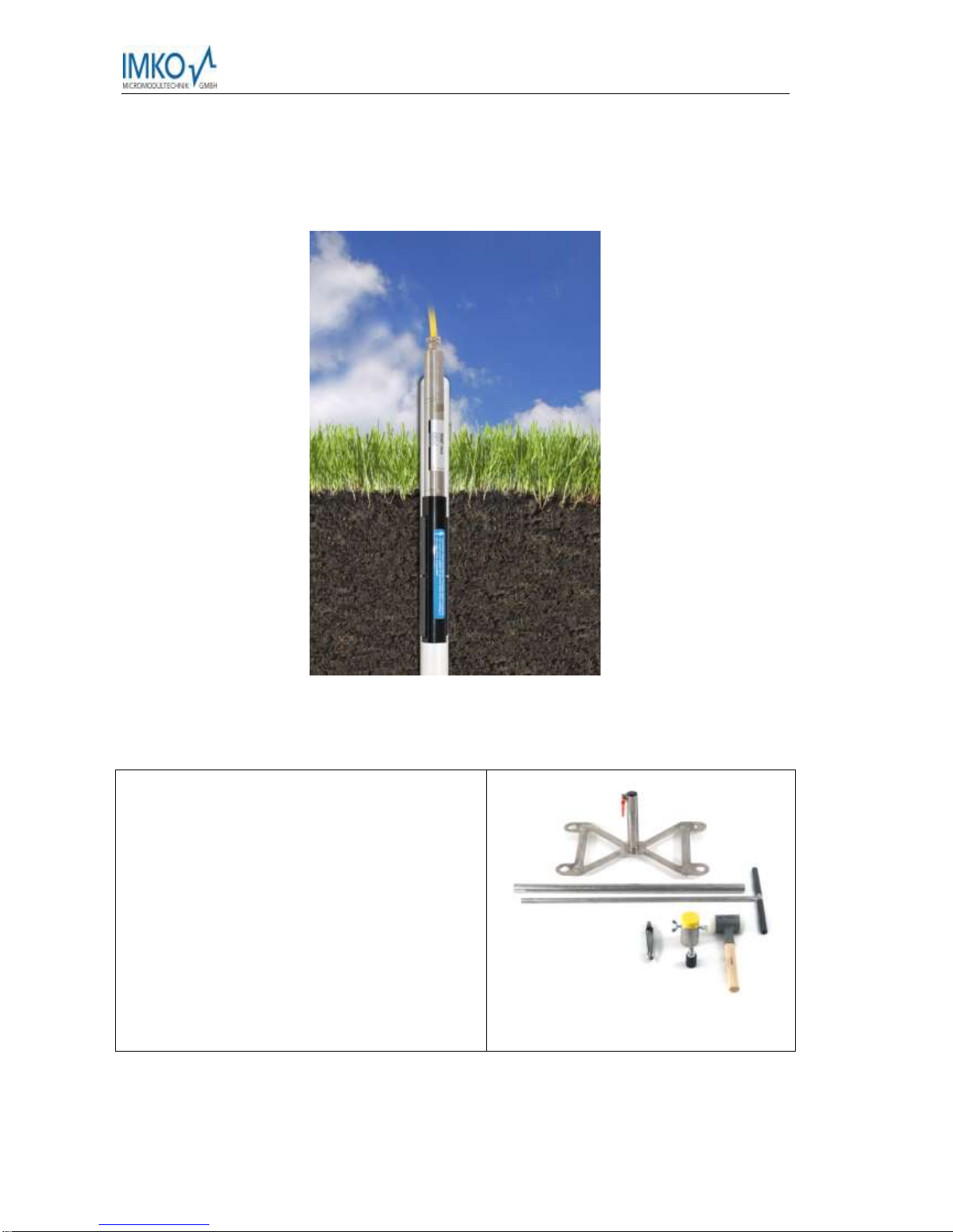
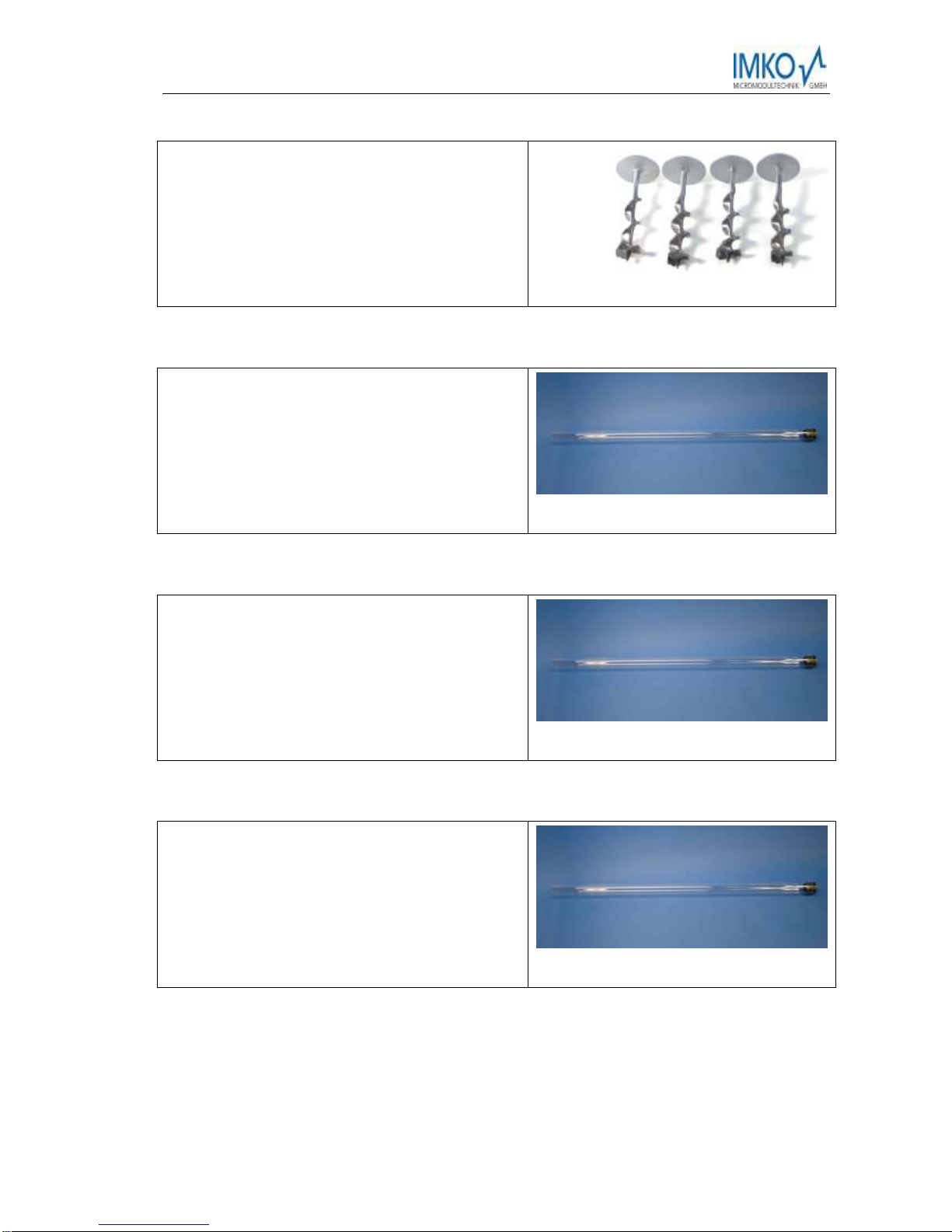
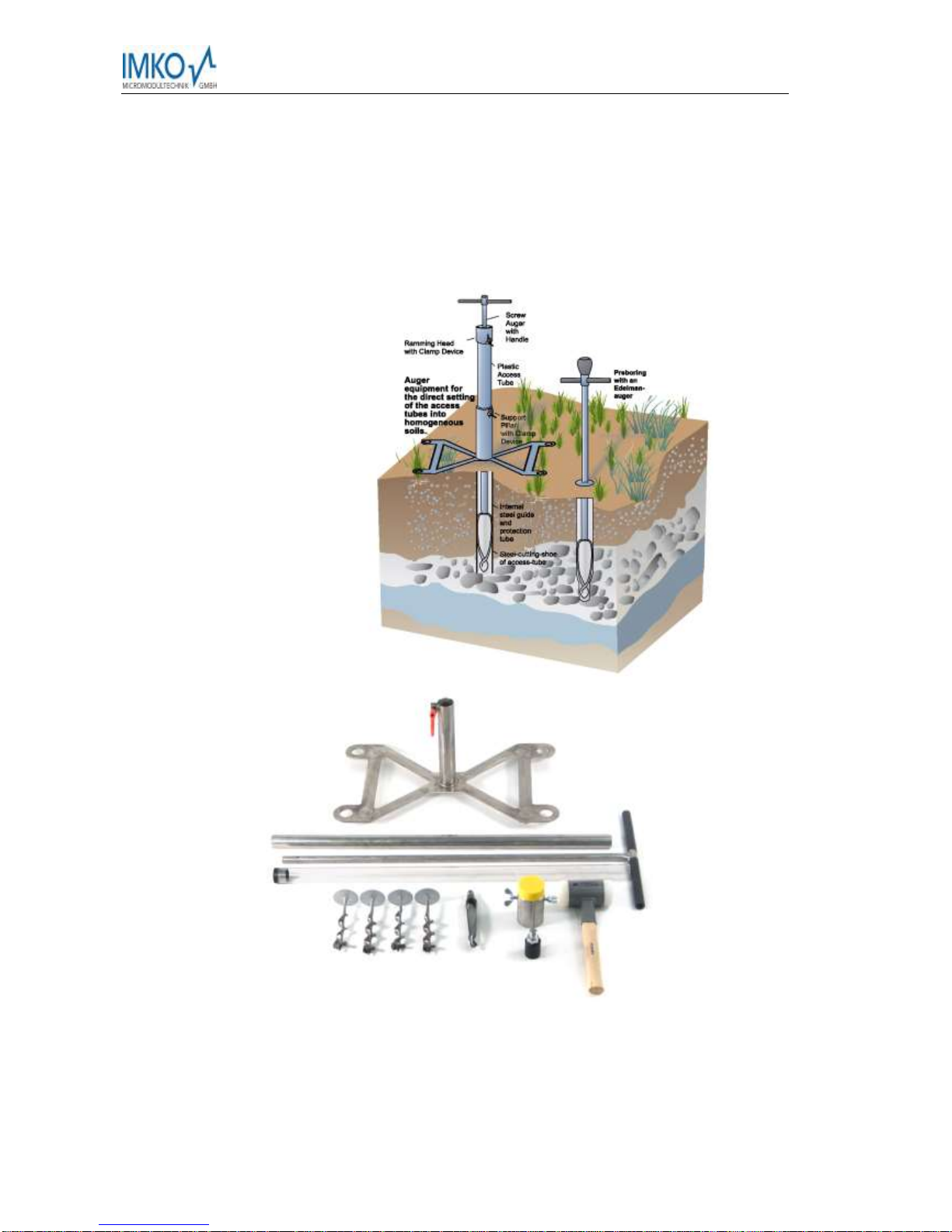
5.2.1 Auger equipment for ø44mm TECANAT tubes
1 x Support pillar with clamp device (stainless
steel),
1 x ramming head with 2 x wing nut (stainless
steel),
1 x shock protection Nylon (TecaRIM) for ramming
head,
1 x clamp device for rubber bung,
1 x Handle 1m (stainless steel),
1 x Edelman auger Ø 34mm,
1 x inner steel guide for 1m-access tubes (stainless
steel),
1 x shock absorbing hammer with nylon heads
Item no.: 303021
2017-05-30 TRIME®-PICO IPH Version 2_0
Page 13
5.2.2 Soil anchor set for auger equipment,
4x soil anchor for fixing the support pillar when
installing 2m/3m TECANAT tubes 44mm.
Item no.: 302022
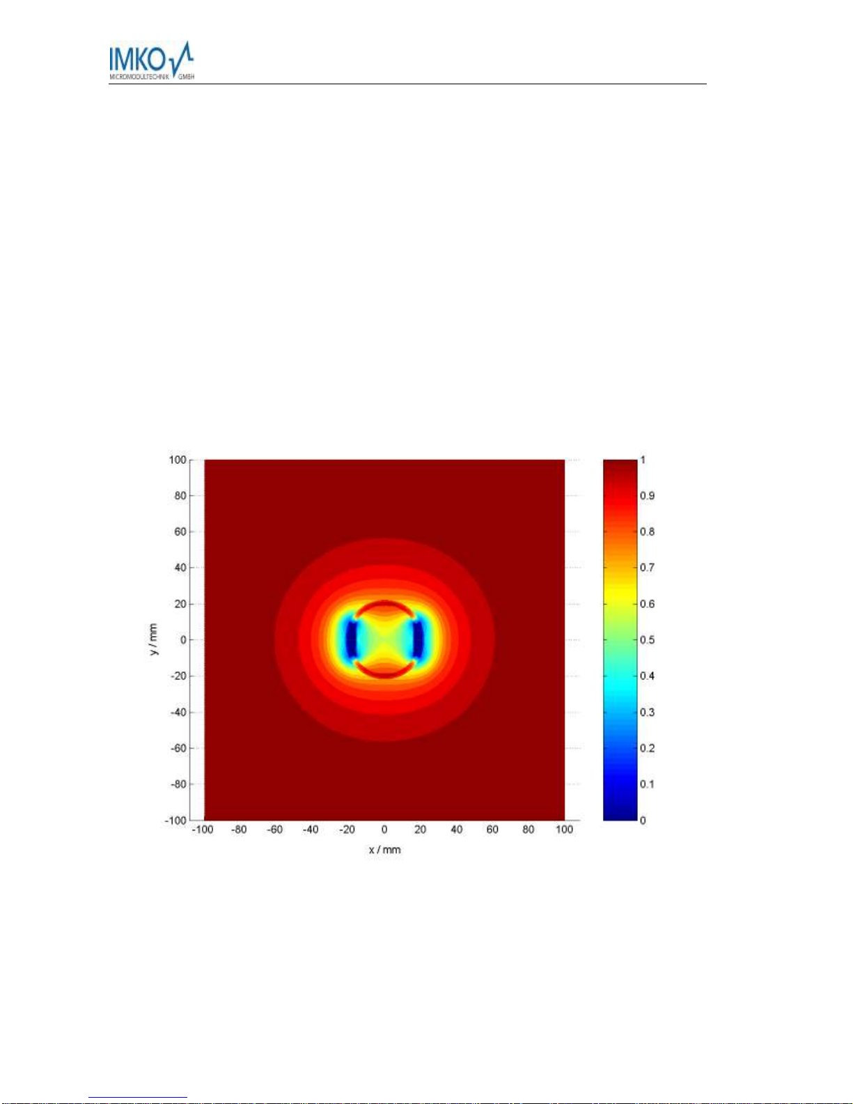
5.2.3 TECANAT access tube 1m / ø44mm
PC tube 44x42mm with steel cutting shoe
1 x rubber bung
1 x cap
1 x neoprene ring
Item no.: 303008
5.2.4 TECANAT access tube 2m / ø44mm
PC tube 44x42mm with steel cutting shoe
1 x rubber bung
1 x cap
1 x neoprene ring
Item no.: 303010
5.2.5 TECANAT access tube 3m / ø44mm
PC tube 44x42mm with steel cutting shoe
1 x rubber bung
1 x cap
1 x neoprene ring
Item no.: 303012
For further options and detailed information please contact IMKO, thanks!

TRIME®-PICO T3/IPH44 IPH50 Version 2_0 2017-05-30
Page 14
6Remote Power Supply to TRIME-PICO IPH
The operation of TRIME sensors may cause problems when power has to be supplied via long
cables. There are limitations to the maximum cable length depending on the cable diameter.
When power is supplied over long distance the maximum cable length depends on the cable
cross section
A
, the supply voltage
Vs
and the number
n
of the sensors measuring simultaneous-
ly. Device-specific data also be applied to the formula:
Power consumption during measurements: Inorm = 100mA @ 12V/DC
Power consumption at min. voltage: Imax = 175mA @ 7V/DC
Supply voltage: Vs =12V
Minimum sensor voltage at circuit end: Vmin = 7V
Wire cross section: A = 0,34mm²
Specific electrical resistance of copper:
= 0.0178Ωx mm² / m
Number of sensors: n = 1…
The maximum possible circuit length Imax can then be calculated in the following manner:
max
min
max 2)( In VVA
ls
Please see the following the following example:
In the IMP232 environmental measurement system a bus cable with a wire cross section of
A = 0.34 mm2is normally used. We further assume that the power supply voltage is Vs=12 V
and only one sensor is designated to measure. Thus n = 1.
m
A
m
mm VVmm
l270
175.010356.0
)712(34.0 2
2
max
In the above calculation, no tolerance is included; for security reasons the calculated cable
length should be reduced by 10% to obtain a realistic value.
In order to increase the maximum possible cable length several solutions are feasible.
1. Using cables with larger conductor diameters
By using 6-core conductor cables instead of 4-core, the cable length can be dou-
bled as two extra cores can be used for power supply. Cables with conductors of
larger diameters will further increase the maximum cable length possible.
2. Increasing the power supply voltage
Power supply voltage can be increased up to 17V, thereby raising the maximum
length from 270m to 540m in the example calculation above.
3. Installation of buffer batteries in the distributor
Additional storage batteries close to the TRIME sensors, e.g. in the distributor, al-
low cable lengths up to 1km and enable simultaneous measurement of several
sensors. However, this method requires an additional charging circuit for the buff-
er storage battery.
4. Installation of a voltage regulator at the distributor
Voltage loss in the cable can be reduced with a 30V power supply and an installa-
tion of a voltage regulator directly in front of the TRIME sensor, thus allowing cir-
cuit lengths of up to 1km.

2017-05-30 TRIME®-PICO IPH Version 2_0
Page 15
Which solution is best suited mainly depends on the nature of the power supply of the meas-
urement system:
Battery supply: solution 1 and possibly solution 3 should be considered, the latter being
relatively expensive.
Mains supply: solutions 1 and 2 could be combined, or, more expensive, solutions 2 or 4
could be chosen.
TRIME®-PICO T3/IPH44 IPH50 Version 2_0 2017-05-30
Page 16
7 The TRIME-PICO IPH Tube Access Probe
7.1 Introduction
The measuring of soil water content with TDR (Time Domain Reflectometry) is now a well estab-
lished method. However water content profiling is not possible with conventional TDR rod
probes. The TRIME-PICO IPH tube probe was developed for this reason.
Since 1994 the TRIME-T3 and the former TRIME-IPH have found numerous applications in earth
and environmental sciences, fulfilling even the most exacting requirements. Now the new
TRIME-PICO IPH replaces the TRIME-IPH and has new additional features, as the measurement
of the temperature and a memory for up to 15 material specific calibrations.
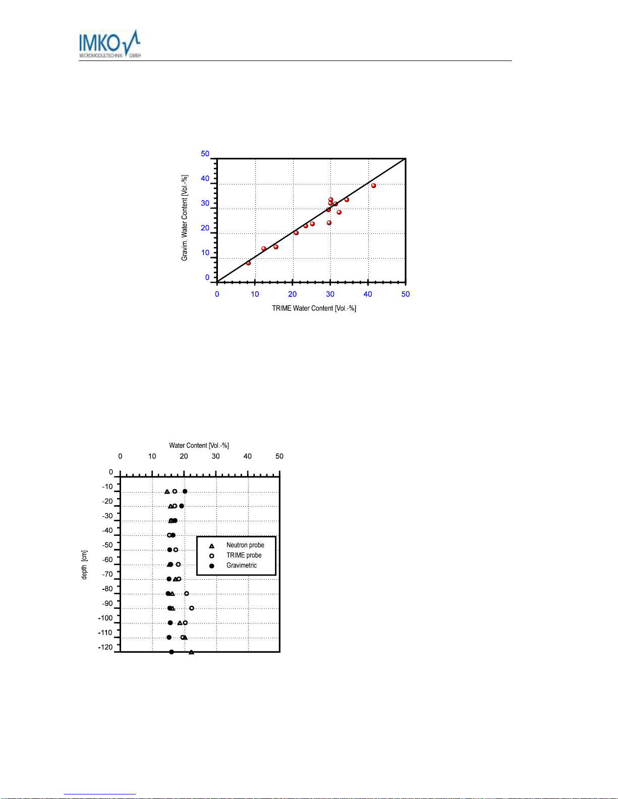
7.2 Measuring Field
The effective penetration depth of the probe is about 15 cm with the highest sensitivity in the
immediate vicinity of the access tube and decreases exponentially with distance. Figure 1 shows
the electric field distribution of the probe and the approximate measuring volume.
Figure 1: Electric field distribution of the TRIME probe and approximate measuring volume.
The elliptical measuring volume enables a higher representation to be achieved by several
measurements rotating the probe after each measurement and calculating the mean value.
Note that the necessity of a close contact between access tube and material is essential
for reliable measurements and that the tubes should be installed by our recommended
method.

2017-05-30 TRIME®-PICO IPH Version 2_0
Page 17
For example at an assumed water content of 15 vol. % an air gap of 1 mm around the
whole length of the tube would result in an underestimation of 1 - 2 vol. %.
At a water content of 25 vol. % the error would be 5 vol.-%.
At very high water contents (50 vol. %) errors may reach 10 vol. %.
In the case of a water filled gap under conditions of saturation the gap error would be
much smaller.
Problems may arise, however, in very inhomogeneous soils and when drilling under very dry
conditions. For these soils other drilling methods are recommended (e. g. pre-boring with an
Edelman auger, washing mud into the cavity around the tube). Losses in accuracy then has to be
accepted, and measurements immediately after installation are not recommended.
Problems can also arise in swelling and shrinking soils, since cracks develop especially along the
access tubes.
TRIME®-PICO T3/IPH44 IPH50 Version 2_0 2017-05-30
Page 18
7.3 Measuring experiences
The TRIME-Technology was thoroughly tested in the field and compared both to neutron probe
measurements and thermo gravimetrically determined values.
Figure 2: Comparison of TRIME measurements and gravimetric water content determination for a clayey soil.
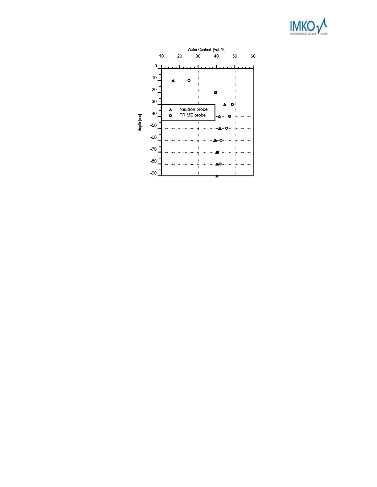
Figures 5 and 6 show a comparison of water content determinations for a loess and for a heavy
clay, made with a neutron probe (Wallingford), the TRIME-T3 probe, and the gravimetric meth-
od. In contrast to the neutron probe, which is not suitable for measurements near the surface
due to radiation losses to the atmosphere, TRIME has no problem at all to measure directly at
the soil surface.
Figure 3: Comparison of neutron probe, TRIME-T3 and gravimetric method for water content determina-
tions in a loess soil.
2017-05-30 TRIME®-PICO IPH Version 2_0
Page 19
Figure 4 : Comparison of neutron probe and TRIME-T3 for water content determinations an illitic clay.
Some materials, especially very clayey soils and soils with high organic contents, can afford ma-
terial specific calibrations due to their different dielectric behaviour.
A limiting factor in TDR measuring is the electrical conductivity. For the TRIME-PICO IPH tube
probe, the pore water conductivity should not exceed 15 dS/m. Note that bulk soil electrical
conductivity is a combination of the pore water electrical conductivity and the surface conductiv-
ity of the soil matrix. Due to the tortuous nature of the conductivity path in the soil (soil type
dependent), the bulk soil conductivity is much lower than the electrical conductivity of the pore
water and it is dependent on water content.
7.4 Summary
The TRIME-PICO IPH tube probe is a promising new tool for determining water content profiles
with the TDR method. Fast, routine and non destructive measurements of water content without
the use of hazardous radioactive materials are possible. A measuring accuracy of 2 vol.-% is
possible, provided that soil and access tube are in close contact and pore water conductivity
doesn’t exceed 15 dS/m.
TRIME®-PICO T3/IPH44 IPH50 Version 2_0 2017-05-30
Page 20
8 Access Tubes and Augers
The penetration depth of the measurement field of the 44mm TRIME tube-access-probe is up to
150mm into the soil. The measurement sensitivity is the highest near the access tube and de-
creases exponentially into the medium. Therefore the insertion method of the access tube is
very important.
Pre-boring of bore holes with standard augers destroy the soil texture, because it is difficult to
come to a good and close contact of the access tube inside the soil. With the described auger
equipment it is possible to set the access tubes directly into homogenous soils without pre-
boring. In very stony soils it is not possible to use this method. Therefore it could be possible to
use an Edelman-Auger for pre-boring and closing the air gaps with mud. Changes in soil struc-
This manual suits for next models
1
Table of contents
Other IMKO Accessories manuals


Popular Accessories manuals by other brands


Master
Master Lift Conveyor Instructions for use and maintenance

Opvimus
Opvimus NS-CAN operating instructions

UWT
UWT NivoGuide 8100 Quick setup guide

GPO
GPO GASPO GC-701S User operating instructions

ABB
ABB Wireless Proximity Switches Planning and Installation Guidelines

Emerson
Emerson MVS205 use instructions

ShadeLab
ShadeLab PIUMA installation manual

elsner elektronik
elsner elektronik KNX AQS/TH-B-UP Technical specifications and installation instructions

Lord MicroStrain
Lord MicroStrain 3DM-GX5-10 user manual

Lab companion
Lab companion IL3-15 Operation manual

ATEN
ATEN VS92A user manual

Tait
Tait TB8100 Installation and operation manual