manuals.online logo
Brands
  1. Home
  2. •
  3. Brands
  4. •
  5. Immergas
  6. •
  7. Boiler
  8. •
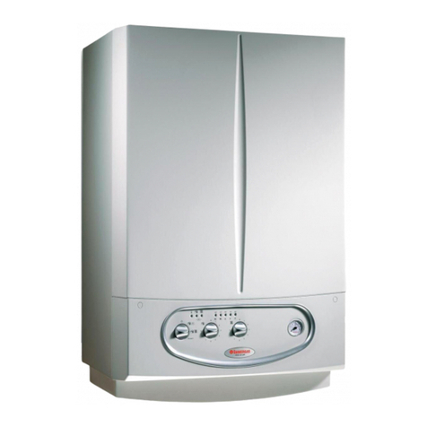
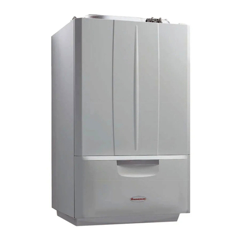
  9. Immergas EOLO Extra 24 kW User manual

Immergas EOLO Extra 24 kW User manual

This manual suits for next models

2

Other Immergas Boiler manuals

Immergas RAPAX 200 V3 Product manual

Immergas

Immergas RAPAX 200 V3 Product manual

Immergas VICTRIX EXA 28 1 ERP Operating instructions

Immergas

Immergas VICTRIX EXA 28 1 ERP Operating instructions

Immergas VICTRIX TERA VIP Product manual

Immergas

Immergas VICTRIX TERA VIP Product manual

Immergas AVIO 24 2 ERP User manual

Immergas

Immergas AVIO 24 2 ERP User manual

Immergas ARES 150 TEC ERP Product manual

Immergas

Immergas ARES 150 TEC ERP Product manual

Immergas VICTRIX PRO 1 I Series Instruction Manual

Immergas

Immergas VICTRIX PRO 1 I Series Instruction Manual

Immergas VICTRIX EXA 24 X 1 ErP Operating instructions

Immergas

Immergas VICTRIX EXA 24 X 1 ErP Operating instructions

Immergas Victrix Pro 80 1 I Product manual

Immergas

Immergas Victrix Pro 80 1 I Product manual

Immergas Nike Star 24 4 ErP Product manual

Immergas

Immergas Nike Star 24 4 ErP Product manual

Immergas ARES PRO 150 Operating instructions

Immergas

Immergas ARES PRO 150 Operating instructions

Immergas VICTRIX 26 2 I User manual

Immergas

Immergas VICTRIX 26 2 I User manual

Immergas EOLO MYTHOS DOM 10 1E Product manual

Immergas

Immergas EOLO MYTHOS DOM 10 1E Product manual

Immergas EOLO Star 23 kW Guide

Immergas

Immergas EOLO Star 23 kW Guide

Immergas NIKE Mini Export User manual

Immergas

Immergas NIKE Mini Export User manual

Immergas VICTRIX EXA 24 X 1 ErP Operating instructions

Immergas

Immergas VICTRIX EXA 24 X 1 ErP Operating instructions

Immergas Victrix Pro 80 1 I Product manual

Immergas

Immergas Victrix Pro 80 1 I Product manual

Immergas Victrix-Zeus-Superior 32 2 ERP Operating instructions

Immergas

Immergas Victrix-Zeus-Superior 32 2 ERP Operating instructions

Immergas EOLO Mini Guide

Immergas

Immergas EOLO Mini Guide

Immergas VICTRIX ZEUS SUPERIOR 26 2 ERP User manual

Immergas

Immergas VICTRIX ZEUS SUPERIOR 26 2 ERP User manual

Immergas VICTRIX EXA 24 X 1 ErP User manual

Immergas

Immergas VICTRIX EXA 24 X 1 ErP User manual

Immergas NIKE MINI 28 KW SPECIAL Product manual

Immergas

Immergas NIKE MINI 28 KW SPECIAL Product manual

Immergas NIKE MYTHOS 24 2 E Product manual

Immergas

Immergas NIKE MYTHOS 24 2 E Product manual

Immergas VICTRIX 50 User manual

Immergas

Immergas VICTRIX 50 User manual

Immergas HERCULES SOLAR 26 2 ErP Operating instructions

Immergas

Immergas HERCULES SOLAR 26 2 ErP Operating instructions

Popular Boiler manuals by other brands

IDEAL IMAX XTRA EL 320 user guide

IDEAL

IDEAL IMAX XTRA EL 320 user guide

UTICA BOILERS BC3D Installation, operation & maintenance manual

UTICA BOILERS

UTICA BOILERS BC3D Installation, operation & maintenance manual

Lochinvar SOLUTION 260000 Installation & service manual

Lochinvar

Lochinvar SOLUTION 260000 Installation & service manual

Weil-McLain EG 6 Series manual

Weil-McLain

Weil-McLain EG 6 Series manual

RBI LCD Series Installation & operation manual

RBI

RBI LCD Series Installation & operation manual

Baxi MainEco Combi 28 Installation and service manual

Baxi

Baxi MainEco Combi 28 Installation and service manual

Unical ALKON R 24 Installation and Servicing Manual

Unical

Unical ALKON R 24 Installation and Servicing Manual

Automatic Heating Gasogen Installation and Servicing Manual

Automatic Heating

Automatic Heating Gasogen Installation and Servicing Manual

Viessmann VITORADIAL 300-T Type VR3 Service instructions for contractors

Viessmann

Viessmann VITORADIAL 300-T Type VR3 Service instructions for contractors

Alpha GasSaver GS-1 Installation and servicing instructions

Alpha

Alpha GasSaver GS-1 Installation and servicing instructions

Baxi ROCA LAURA PLUS 28/28 Operating, cleaning and maintenance instructions for the user

Baxi

Baxi ROCA LAURA PLUS 28/28 Operating, cleaning and maintenance instructions for the user

Vaillant uniSTOR VIH SW GB 500 BES operating instructions

Vaillant

Vaillant uniSTOR VIH SW GB 500 BES operating instructions

Kärcher HWE 4000 Gas manual

Kärcher

Kärcher HWE 4000 Gas manual

Radijator BIO max 23.1 instruction manual

Radijator

Radijator BIO max 23.1 instruction manual

Granby BKC Installation, operation and maintenance manual

Granby

Granby BKC Installation, operation and maintenance manual

Brunner BSV 20 Instructions for use

Brunner

Brunner BSV 20 Instructions for use

Potterton 50e Installation and Servicing Manual

Potterton

Potterton 50e Installation and Servicing Manual

UTICA BOILERS TriFire Assembly instructions

UTICA BOILERS

UTICA BOILERS TriFire Assembly instructions

manuals.online logo
manuals.online logoBrands
  • About & Mission
  • Contact us
  • Privacy Policy
  • Terms and Conditions

Copyright 2025 Manuals.Online. All Rights Reserved.

EOLO Extra kW
Instant wall-hung boilers
airtight chamber
for outdoors
EOLO Extra kW
1
STEEkW ed 01/06 EOLO Extra kW
Technical Documentation Technical Documentation
EOLO Extra kW
Wall-hung room sealed fan assisted boiler for
outdoors.
EOLO Extra 24 kW
EOLO Extra 28 kW
EOLO Extra 32 kW
EOLO Extra kW is a wall-hung room-sealed fan-assisted
boiler (type C) for central heating and producing domestic
hot water.
e boilers of the EOLO Extra kW series are type-approved
for installing outside the building in the open, using a top
cover kit (optional).
e boiler is available with an output power of 24 kW (20,640
kcal/h), 28 kW (24,080 kcal/h) and 32 kW (27,520 kcal/h).
One of the standard features on the boiler is an antifreeze
system that protects against temperatures as low as -15°C (but
the connecting pipes have to be lagged).
e boiler is easily controlled remotely controlled by a
Remote Control (see the CAR technical data sheet) which works
together with a microprocessor controlled p.c.b. with continuo-
us 2-sensor flame modulation (d.h.w. and central heating).
e knobs on the control panel are for setting boiler ope-
rating parameters. is panel visually displays status and the
functioning mode with the LEDs on it. Malfunctions can also
be seen on the Remote Control display.
e hydraulic circuit is equipped with a water-gas exchan-
ger in copper that uses a new 3-way electric valve group
and a new pump group made in a composite material on
which the circulator and the devices to control the hydraulic
circuit are housed (the system’s absolute pressure switch, a 3-bar
safety valve, an automatic system by-pass, etc.).
General features.
e supply of combustion air to inside the sealed chamber and
the expulsion of fumes are ensured by a fan whose correct ope-
ration is controlled by a differential fumes pressure switch.
2
STEEkW ed 01/06 EOLO Extra kW
Technical DocumentationTechnical Documentation
EOLO Extra 24 kW main dimensions and connections.
Legend:
G - Gas supply
AC - D.h.w. outlet
AF - D.h.w. (cold) inlet
R - System return
M - System delivery
V - Electrical connection
Height (mm) Width (mm) Depth (mm)
775 440 240
CONNECTIONS
GAS DOMESTIC
WATER SYSTEM
G AC AF R M
1/2” 1/2” 1/2” 3/4” 3/4”
EOLO Extra 28-32 kW main dimensions and connections.
Legend:
G - Gas supply
AC - D.h.w. outlet
AF - D.h.w. (cold) inlet
R - System return
M - System delivery
V - Electrical connection
Height (mm) Width (mm) Depth (mm)
775 520 250
CONNECTIONS
GAS DOMESTIC
WATER SYSTEM
G AC AF R M
1/2” 1/2” 1/2” 3/4” 3/4”
3
STEEkW ed 01/06 EOLO Extra kW
Technical Documentation Technical Documentation
Legend:
1 - Stand by LED
2 - Burner on LED
3 - D.h.w. on LED
4 - Central heating on LED
5 - Temperature LED – Ignition stop malfunction
6 - Temperature LED – Flue pressure switch malfunction
7 - Temperature LED – System pressure insufficient malfunction
8 - Temperature LED – Circulation insufficient malfunction
9 - Temperature LED – Delivery probe faulty
10 - Temperature LED – Domestic hot water probe faulty (optional)
11 - Temperature LED – Overheating lock
12 - Stand-by / On / Programming / Reset main switch
13 - Parameters selection knob
14 - Parameters modification knob
15 - Boiler manometer
EOLO Extra kW Control panel.
4
STEEkW ed 01/06 EOLO Extra kW
Technical DocumentationTechnical Documentation
EOLO Extra 24 kW main components.
Legend:
1 - Boiler pressure gauge
2 - Domestic water probe
3 - D.h.w. flow switch
4 - Gas valve
5 - System pressure switch
6 - Burner
7 - Combustion chamber
8 - Airtight chamber
9 - Fan
10 - Testing hole (air A) - (fumes F)
11 - Pressure point with positive signal
12 - Pressure point with negative signal
13 - Flue pressure switch
14 - Delivery probe
15 - Safety thermostat
16 - Draught diverter
17 - Primary exchanger
18 - Ignition and detection electrodes
19 - System expansion vessel
20 - Automatic air vent
21 - Boiler circulator
22 - D.h.w. exchanger
23 - 3-bar valve (motorised)
24 - Automatic by-pass
25 - 3-way safety valve
26 - System draining cock
27 - Domestic water draining fitting
28 - System filling valve
5
STEEkW ed 01/06 EOLO Extra kW
Technical Documentation Technical Documentation
EOLO Extra 28-32 kW main components.
Legenda:
1 - Domestic water draining fitting
2 - Domestic water probe
3 - D.h.w. flow switch
4 - Gas valve
5 - System pressure switch
6 - Burner
7 - Combustion chamber
8 - Airtight chamber
9 - Fan
10 - Testing hole (air A) - (fumes F)
11 - Pressure point with positive signal
12 - Pressure point with negative signal
13 - Flue pressure switch
14 - Delivery probe
15 - Safety thermostat
16 - Draught diverter
17 - Primary exchanger
18 - Ignition and detection electrodes
19 - System expansion vessel
20 - Automatic air vent
21 - Boiler circulator
22 - D.h.w. exchanger
23 - 3-way valve (motorised)
24 - Automatic by-pass
25 - 3-bar safety valve
26 - System draining cock
27 - Boiler pressure gauge
28 - System filling valve
6
STEEkW ed 01/06 EOLO Extra kW
Technical DocumentationTechnical Documentation
EOLO Extra kW hydraulic diagram.
Legend:
1 - D.h.w. flow switch
2 - Flow limiter
3 - System filling valve
4 - Domestic water probe
5 - Gas valve
6 - Burner
7 - Primary exchanger
8 - Draught diverter
9 - Fan
10 - Airtight chamber
11 - Flue pressure switch
12 - Delivery probe
13 - Safety thermostat
14 - System expansion vessel
15 - Automatic air vent
16 - Boiler circulator
17 - System pressure switch
18 - D.h.w. exchanger
19 - 3-way valve
20 - Automatic by-pass
21 - System draining cock
22 - 3-bar safety valve
G - Gas supply
AC - D.h.w. outlet
AF - D.h.w. (cold) inlet
R - System return
M - System delivery
Hot water for central heating and domestic use is produced
by a primary and secondary (d.h.w.) circuit that are engaged
according to requirements.
7
STEEkW ed 01/06 EOLO Extra kW
Technical Documentation Technical Documentation
Primary circuit (boiler circuit).
e primary circuit with relevant control and safety devices
is triggered each time there is a request for central heating
or domestic hot water.
Operation.
e heat contained in the flue produced by combustion is ab-
sorbed by the copper blades of the primary water-gas exchanger
(7) which, in turn, transfers it to the water circulating inside
it by means of the boiler pump (16).
e water is transferred directly into the system or else can
be diverted inside the stainless steel instantaneous plate ex-
changer (18).
is depends on the position of the motorised 3-way valve
(19) which, when idle, lets the water flow through the d.h.w.
exchanger (18); on the other hand, when responding to a heat-
ing request, the flow is diverted to the system delivery (M) and
return (R) pipes.
Flow-head graph.
e trend of the curve that represents the system’s flow-head
ratio depends on how fast the pump is working and on how
the system by-pass is adjusted. Depending on the position, it
provides the system with a higher or a smaller head. e cha-
racteristic curves are shown in the following graphs.
D
Flow-rate l/h
A
Head (m H2O)
EOLO Extra 24 kW
Head (kPa)
Flow-rate l/h
Head (m H2O)
EOLO Extra 28 kW
B
C
A
B
C
D
Head (kPa)
A = Head available to the system on maximum speed with the by-pass off.
B = Head available to the system on maximum speed with the by-pass on.
C = Head available to the system at second speed with the by-pass off.
D = Head available to the system at second speed with the by-pass on.
8
STEEkW ed 01/06 EOLO Extra kW
Technical DocumentationTechnical Documentation
Boiler circulator (1).
It works on the primary circuit return, located immediately
after the 3-way diverter valve to which it is connected.
It is part of the integrated multi-function unit made in a
compound material.
A space on the body houses the automatic air vent (2).
Primary exchanger (1).
It is a water-gas lamellar exchanger with copper pipes and
fins (N° 75 fins 24 kW version) (N° 98 fins 28 and 32 kW
version). e central heating delivery NTC probe (2) and the
overheating safety thermostat (3) are located on the exchanger’s
outlet (delivery).
e four pipes it is made of are connected in series (4).
It is connected to the pump delivery and primary circuit deli-
very by means of pipes with threaded fittings.
1
34
2
Delivery
Return
1
2
EOLO Extra 32 kW
Flow-rate l/h
A
B
C
D
A = Head available to the system on maximum speed with the by-pass off.
B = Head available to the system on maximum speed with the by-pass on.
C = Head available to the system at second speed with the by-pass off.
D = Head available to the system at second speed with the by-pass on.
Head (m H2O)
Head (kPa)