manuals.online logo
Brands
  1. Home
  2. •
  3. Brands
  4. •
  5. Immergas
  6. •
  7. Thermostat
  8. •
  9. Immergas SMARTECH PLUS Product manual

Immergas SMARTECH PLUS Product manual

1
Code 1.044741 - Rev. ST.005019/003 - 10/2021
immergas.com
Immergas S.p.A. 42041 Brescello (RE) - Italy
Tel. 0522.689011 Fax 0522.680617
IEInstructions and warnings
Hereby Immergas S.p.A., declares that the radio equip-
ment type "Smartech Plus" is in compliance with Directive
2014/53/EU.
e full text of the EU declaration of conformity is available
at the following Internet adress: www.immergas.com
FOREWORD.
is is an abridged version of the instruction manual, does
not replace the full version. e full version is available
online: www.immergas.com.
e “Smartech Plus” has been designed to guarantee
ideal temperature conditions at any time of the day and
night for each individual day of the week, with chance to
use it via Cloud.
Its installation takes a few minutes: the Gateway is pow-
ered by the 230 Volt AC mains and connected to the gen-
erator via IMG Bus; there is also a clean contact to work
with boilers that do not have an IMG Bus. e Gateway is
connected via Bluetooth system to the Chrono-thermostat
and via Wi-Fi to the Cloud. While the Chrono-thermostat,
with independent battery power supply, does not require
any electrical connection and is equipped with an e-ink
technology display for displaying information: room
temperature, mode, etc. It comes with its own table base
or alternatively it can be wall-mounted.
e "Smartech" application must be downloaded from
the Store iOS and/or Android and installed on the mobile
device (smartphone).
On completion of installation it is ready to function
thanks to the pre-set program inside. Programming the
Smartech Plus is extremely easy and a display and/or an
App allow constant control of all values set.
GENERAL WARNINGS.
is manual was intended for: the Installer and includes
also basic instructions for end user.
• Carefully read the warnings contained in this docu-
ment as they provide indications on how to use the
“Smartech” app, the technical features, the installation,
assembly, programming, adjustment and use instruc-
tions.
• e system must be compliant with applicable stan-
dards.
• e instruction manual must be considered a part of the
“Smartech” application and must be “kept for future
reference”.
• Aer having removed the packaging, check the inte-
grity of the Gateway and chrono-thermostat module.
If in doubt, do not use them and contact the Dealer or
Manufacturer.
• e Gateway module and the chrono-thermostat are
only intended for the use which they have been speci-
cally designed for. Any other use must be considered
improper and therefore dangerous.
• Our products are manufactured in compliance with the
Safety Standards in force. It is, therefore, recommen-
ded to use all devices and attention in such a way that
injury/damage is not caused to persons or objects.
• Do not disassemble parts of the Gateway module or
the Chrono-thermostat when they are in operation.
• Do not use the Gateway module and the Chrono-
thermostat exposed to heat sources or under the hot
sun.
• e manufacturer will not be held responsible in the
following cases:
a) Incorrect installation.
b)Boiler functioning defects to which the chrono-
thermostat and the Gateway module are applied.
c) Unauthorised changes or tampering.
d)Total or partial failure to comply with instructions.
e) Exceptional events etc.
CLEANING THE CASE.
Use a dry cloth to clean the cover of the Gateway module
and the chrono-thermostat. Never use abrasive or powder
detergents.
WARNING.
Immergas reserves the right to make improvements and
changes to details and accessories, excepting the essential
features of the model described and illustrated herein.
Cod. 1.044741 - Rev. ST.005019/003 - 10/2021
SMARTECH PLUS
Cronotermostato Smart
immergas.com
Immergas S.p.A. 42041 Brescello (RE) - Italy
Tel. 0522.689011 Fax 0522.680617
IT
Istruzioni e avvertenze
di installazione
Il fabbricante Immergas S.p.A., dichiara che il tipo di
apparecchiatura radio "Smartech Plus" è conforme alla
direttiva 2014/53/UE.
Il testo completo della dichiarazione di conformità UE è dis-
ponibile al segunete indirizzo Internet: www.immergas.com
PREMESSA.
Questa è una versione ridotta del manuale istruzioni, che
però non sostituisce quella completa. La versione comple-
ta è comunque disponibile online: www.immergas.com
Lo “Smartech Plus” è stato progettato per garantire
condizioni di temperatura ideali in ogni momento del
giorno e della notte per ogni singolo giorno della settima-
na, con la possibilità di utilizzo tramite Cloud.
La sua installazione richiede pochi minuti: il Gateway
viene alimentato tramite la rete elettrica a 230 Volt AC e
collegato al generatore tramite IMG Bus; è presente anche
un contatto pulito per poter lavorare con le caldaie non
dotate di questo Bus di comunicazione. Il Gateway viene
connesso tramite sistema Bluetooth al Cronotermostato
e tramite Wi-Fi al Cloud. Mentre il Cronotermostato, con
alimentazione indipendente a batteria, non necessita di
nessun collegamento elettrico ed è dotato di un display
con tecnologia e-ink per la visualizzazione delle infor-
mazioni: temperatura ambiente, modalità, ecc. Viene
fornito con la sua base da tavolo o in alternativa può
essere installato a muro.
L’applicazione “Smartech” dovrà essere scaricata dallo
Store iOS e/o Android e installata su dispositivo mobile
(smartphone).
Terminata l'installazione, il cronotermostato è già funzio-
nante, grazie al programma preimpostato al suo interno.
La programmazione dello Smartech Plus è di estrema
facilità e tramite App e/o un display permette un costante
controllo di tutti i valori impostati.
AVVERTENZE GENERALI.
Il presente manuale è stato redatto per: l’Installatore
e include anche istruzioni di base per l’utente nale.
• Leggere attentamente le avvertenze contenute nel pre-
sente documento che danno indicazioni sull’utilizzo
dell’applicazione “Smartech”, le caratteristiche tecniche,
le istruzioni di installazione, montaggio, programma-
zione, regolazione e uso.
• L’esecuzione dell’impianto deve essere rispondente alle
norme vigenti.
• Il manuale istruzioni è da considerare parte dell’ap-
plicazione “Smartech” e deve essere “conservato per
futuri riferimenti”.
• Dopo aver tolto l’imballaggio, assicurarsi dell’integrità
del modulo Gateway e del cronotermostato. In caso di
dubbio, non utilizzarli e rivolgersi al Rivenditore o al
Costruttore.
• Il modulo Gateway e il cronotermostato sono destinati
soltanto all’uso per il quale sono stati espressamente
concepiti. Ogni altro uso è da considerarsi improprio
e quindi pericoloso.
• I Nostri prodotti sono realizzati in conformità alle
vigenti normative di sicurezza per cui si raccomanda
l’uso di tutti quei dispositivi o attenzioni in modo che
l’utilizzo non rechi danno a persone o a cose.
• Non smontare parti del modulo Gateway o del Crono-
termostato quando questi sono in funzione.
• Non usare il modulo Gateway e il Cronotermostato
esposti a fonti di calore o sotto il sole cocente.
• Il costruttore si ritiene sollevato da eventuali respon-
sabilità nei seguenti casi:
a) Installazione non corretta.
b) Difetti di funzionamento della caldaia alla quale sono
applicati il modulo Gateway e il Cronotermostato.
c) Modiche o interventi non autorizzati.
d)Inosservanza totale o parziale delle istruzioni.
e) Eventi eccezionali ecc.
PULIZIA DEL RIVESTIMENTO.
Per pulire il rivestimento del modulo Gateway e del Cro-
notermostato usare un panno asciutto. Non usare detersivi
abrasivi o in polvere.
AVVERTENZA.
Immergas si riserva la facoltà, ferme restando le caratte-
ristiche essenziali del modello qui descritto ed illustrato,
di apportare miglioramenti e modiche a particolari ed
accessori.
1. INSTALLAZIONE.
1.1 Avvertenze di installazione.
L’installazione del modulo Gateway, comprensiva dei
relativi cavi e dei collegamenti alla caldaia, deve essere
eseguita da personale specializzato. All’atto della verica
iniziale gratuita della caldaia, allorchè il modulo Gate-
way risulti inserito nell’impianto, il Centro Assistenza
Autorizzato Immergas ne verica il collegamento alla
morsettiera del generatore ed il regolare funzionamento.
Non è prevista da parte del Centro Assistenza Autorizzato
Immergas la verica gratuita del solo modulo Gateway se
richiesta successivamente alla fase di avvio della garanzia
della caldaia.
Attenzione: dalle operazioni di verica gratuita della
caldaia sono escluse la posa in opera dei cavi del modulo
Gateway, di competenza della ditta installatrice.
1.2 Contenuto della confezione.
Rif Descrizione
1 1 Foglio istruzioni
21 cronotermostato installato sulla base da
tavolo
3 1 modulo Gateway
4
1 cavo di collegamento alla caldaia/unità interna
per modulo Gateway lungo 80 cm
5
2 supporti installazione a muro dotati di livella
a bolla, viti e tasselli
6
2 pile AAA da 1,5V
7
1 cavo di collegamento all’unità esterna per
modulo Gateway lungo 80 cm (se applicabile)
1.3 Dimensioni principali
Cronotermostato Smartech Plus.
1
71.5 35.5
90 102
77
Misure in mm
1.4 Dimensioni principali
modulo Gateway.
2
26
54
70
26
1.5 Operazioni di installazione modulo Gateway e
Cronotermostato.
N.B.: il supporto per l'installazione a parete è il medesimo
sia per ssare il modulo Gateway che il Cronotermostato
nel caso non si utilizzasse la sua base da tavolo.
Fissaggio modulo Gateway (Fig. 3):
installare il supporto da muro (2) ssandolo alla parete
tramite i tasselli ad espansione (1) e le viti in dotazione (3).
Dopo aver cablato il modulo Gateway (4) (come descritto
nel presente foglio istruzioni), agganciarlo a pressione sopra
al supporto installato e inne bloccarlo serrando le due viti
di ssaggio (5).
1
2
3
4
3
5
3
1. INSTALLATION.
1.1 Installation recommendations.
e Gateway module, including the relative cables and
connections to the boiler, must be installed by specialised
sta. On the free initial check of the boiler, when the Ga-
teway module is inserted into the system, the Immergas
authorised Aer-sales Centre checks the connection to
the generator terminal board and adjusts functioning. e
free check just of the Gateway module is not envisioned by
the Immergas authorised Aer-sales Centre is requested
successively to the start phase of the boiler warranty.
Attention: laying the Gateway module cables is excluded
from the free boiler checks; it is the responsibility of the
installer company.
1.2 Package contents.
Ref Description
1 1 Instruction sheet
21 chrono-thermostat installed on the table
base
3 1 Gateway module
4
1 boiler/indoor unit connection cable 80 cm
long for Gateway module
5
2 wall-mounted installation supports equipped
with spirit level, screws and plugs
6
2 AAA 1.5V batteries
7
1 outdoor unit connection cable 80 cm long for
Gateway module (if applicable)
1.3 Main dimension
Chrono-thermostat
Smartech Plus.
1
71.5 35.5
90 102
77
Dimensions in mm
1.4 Main dimension
Gateway module.
2
26
54
70
26
1.5 Gateway and Chrono-thermostat module instal-
lation operations.
N.B.: the wall-mounted support installation is the same both
for xing the Gateway module and the Chrono-thermostat
in case its table base is not used.
Gateway module xing (Fig. 3):
install the wall-mounted support (2) x it to the wall by
means of expansion plugs (1) and the supplied screws (3).
Aer wiring the Gateway module (4) (as described in this
instruction sheet), press-couple it on top of the installed
support and nally lock it by tightening the two xing
screws (5).
1
2
3
4
3
5
3
SMARTECH PLUS
Smart Chrono-thermostat
2
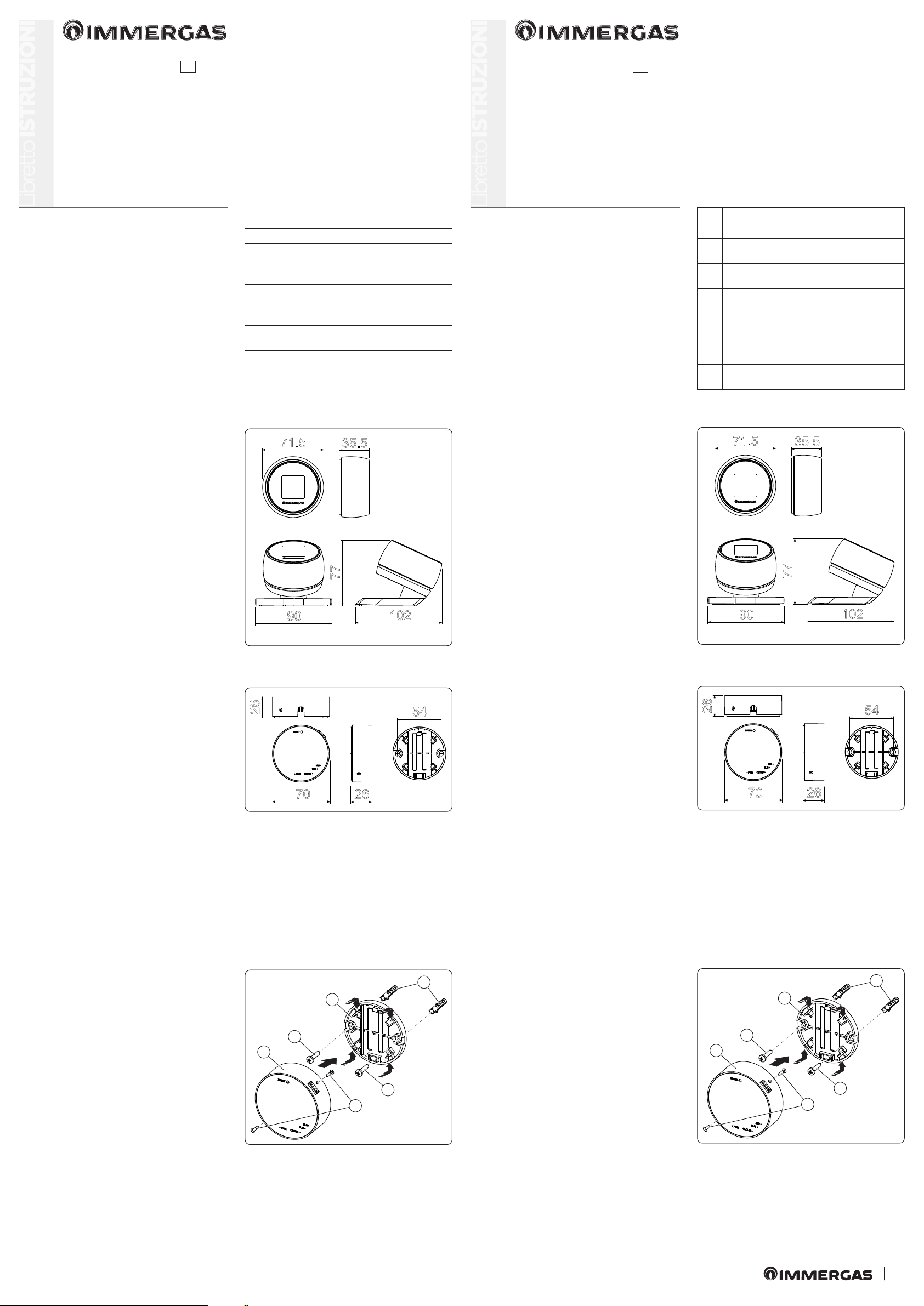
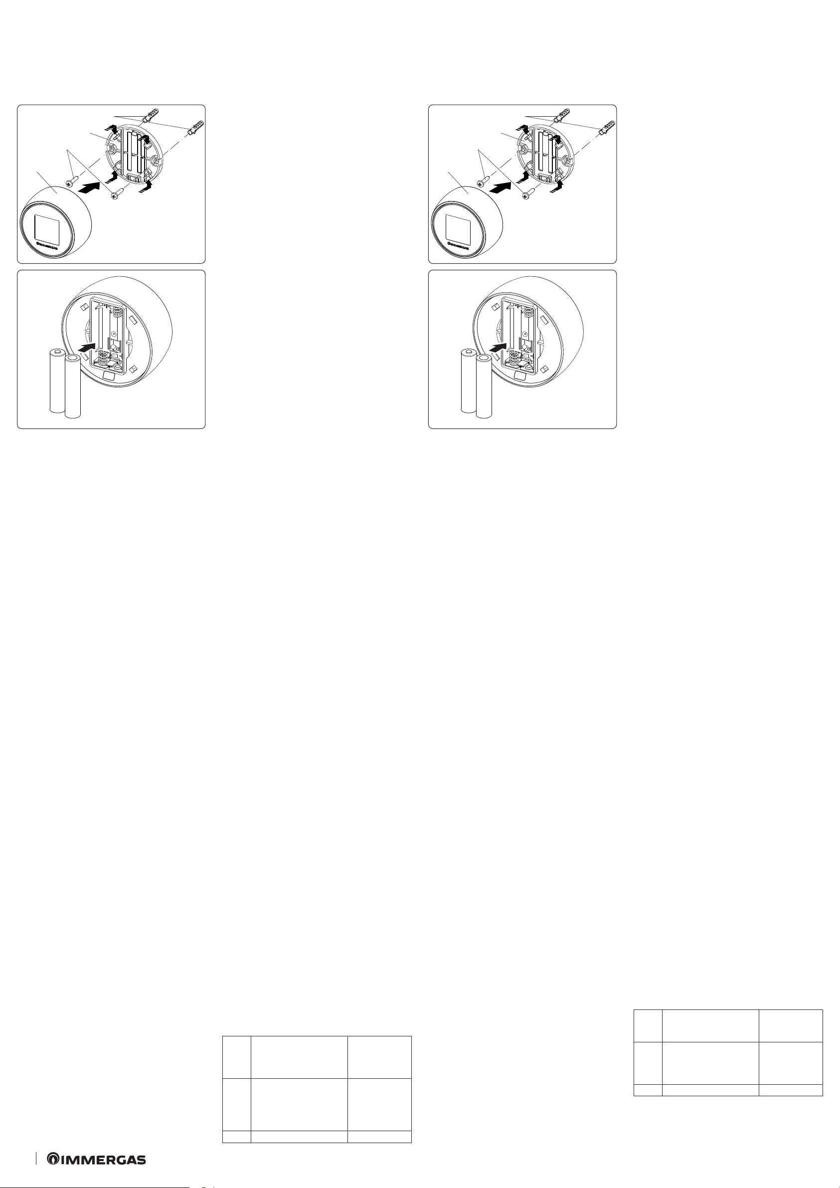
Fissaggio Cronotermostato (Fig. 4):
installare il supporto da muro (2) ssandolo alla parete
tramite i tasselli ad espansione (1) e le viti in dotazione
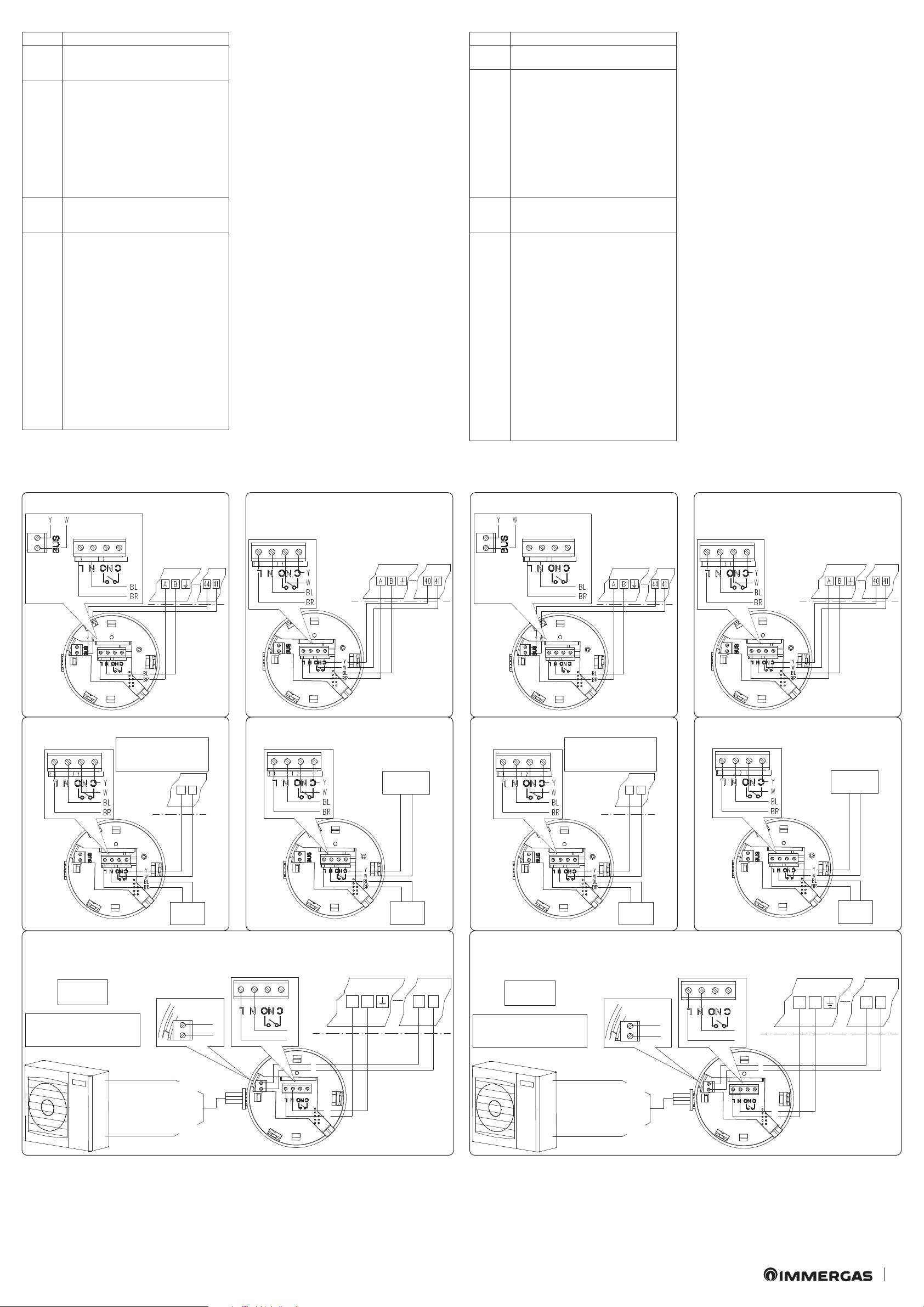
(3). Inserire le 2 batterie tipo AAA da 1.5V (fornite) (Fig.
5); il Cronotermostato (4) poi, si aggancia (o si rimuove) a
pressione sopra al supporto (2).
A ne installazione rimuovere la pellicola protettiva dal
display del Cronotermostato.
4
2
1
3
4
5
N.B.: assicurarsi che la zona di installazione del modulo
di ricezione/trasmissione dati (Gateway) riceva adegua-
tamente il segnale della rete Wi-Fi di casa e del Bluetooth
del Cronotermostato.
Per eettuare i collegamenti elettrici (vedi capitolo 4) non
si deve operare con caldaia in tensione. Il collegamento
deve avvenire rispettando la polarità L-N.
Collegare quindi il modulo Gateway ai morsetti di caldaia
previsti e alimentarlo collegandolo alla rete elettrica.
N.B.: fare riferimento ai collegamenti elettrici riportati
nel capitolo 4.
L’allacciamento alla caldaia deve essere eettuato con il
cavo quadripolare speciale tipo "Y" in dotazione, lungo
80 cm.
N.B.: per una corretta installazione predisporre una linea
dedicata per il collegamento del modulo Gateway secondo
le normative vigenti riguardanti gli impianti elettrici. Se
questo non fosse possibile eventuali disturbi dovuti ad al-
tri cavi elettrici potrebbero causare il mal funzionamento
del modulo stesso.
Dopo aver alimentato la caldaia, il modulo Gateway e il
Cronotermostato (Parag. 4) attendere circa 30 secondi
prima di eettuare la congurazione in modo che la
comunicazione fra modulo Gateway, caldaia e Crono-
termostato si sia stabilizzata.
N.B.: tutti i cronotermostati "Smartech Plus" sono già
congurati per poter funzionare correttamente con il
proprio Gateway, quindi non necessitano di alcuna con-
gurazione aggiuntiva per farli funzionare.
Nel caso di malfunzionamento è possibile resettare il
modulo Gateway procedendo come descritto di seguito:
- assicurarsi di avere acceso il Gateway da almeno 5
minuti;
- tenere premuto il pulsante "Reset" no a vedere il Led
"BLE" che da 5 lampeggi veloci al secondo, esegue un
lampeggio al secondo;
- sul cronotermostato dalla schermata principale, tenere
premuto per 3 secondi no a far comparire il menù
"Mode" o "Program" e ruotare no a visualizzare il
menù "Settings", premere e ruotare per entrare nel
menù "Diagnostic", premere per entrare nel menù;
- premere nuovamente sul cronotermostato, comparirà
il messaggio "Pairing", quando compare "Disconnect",
il cronotermostato è associato al Gateway;
- premere a lungo sul cronotermostato no a tornare al
menù principale;
- spegnere (togliendo tensione) e riaccendere il Gateway.
1.6 Operazioni di download e installazione applica-
zione sui dispositivi mobili (smartphone).
Utilizzando il dispositivo mobile su cui si vuole installare
l’applicazione, collegarsi al relativo Store di applicazioni
di riferimento: App Store (Apple) o Play Store (Android)
e digitare “Immergas smartech” nel campo di ricerca.
L’applicazione funziona con sistema operativo IOS 12 o
superiore (Apple) e Android 10 o superiore. Selezionare
l’applicazione gratuita “Smartech” e attendere il suo
download e installazione sul dispositivo mobile utilizzato.
Aprire la App “Smartech” e scaricare il manuale di istru-
zioni premendo sul bottone “Istruzioni e avvertenze”.
Seguire le istruzioni in esso riportate per procedere alla
registrazione e associazione con il cronotermostato.
Il manuale è scaricabile anche dal sito www.immergas.
com.
N.B: il nome della rete Wi-Fi e la password a cui verrà
collegato lo “Smartech Plus” non deve contenere al suo
interno il simbolo “&” e la metodologia di criptazione
deve essere la WPA2 PSK; in caso contrario potrebbero
esserci delle incompatibilità.
Congurazione tipologia impianto senza Wi-Fi
(modalità temporanea):
questa modalità è temporanea, ed è prevista al solo
scopo di congurare il Cronotermostato in base al tipo
d’impianto al primo avviamento, nel caso non sia dis-
ponibile una connessione internet. La seguente modalità
temporanea resterà attiva no alla rimozione delle batterie
dal Cronotermostato, riportando l’impianto in modalità
di default.
Per selezionare in modo durevole la tipologia d’impianto
è necessario completare la procedura di registrazione
Utente tramite App Smartech (Paragr 1.6).
Smartech Plus è di default in modalità IMGBUS + TA per
coprire la maggior parte degli impianti.
Nel caso di connessione ad impianti con Victrix Hybrid
o Superior pre 2020 è possibile selezionare temporanea-
mente una modalità specica nel seguente modo:
- connettere il Gateway all’impianto ed alimentarlo
correttamente;
- inserire le batterie all’interno del Cronotermostato;
- una volta visualizzato il logo Immergas, tenere premuto
il Cronotermostato no alla visualizzazione dell’elenco
impianti;
- ruotare il Cronotermostato sul tipo d’impianto desid-
erato;
- premere il Cronotermostato per confermare.
2. MODALITÀ DI SICUREZZA
SMARTECH PLUS
N.B.: solo nella modalità: "O" o "Inverno", il Cronoter-
mostato Zona 1 principale è l'unico, nel caso di più Zone,
a poter attivare questa "Modalità di sicurezza".
Il Gateway va in "Modalità di sicurezza" quando viene a
mancare la connessione con il Cronotermostato o quando
si esauriscono le sue batterie.
Nel caso di una mancata connessione, sul display del
Cronotermostato compare la scritta "Disconnected" a
conferma della mancata comunicazione tra i dispositivi
Bluetooth; mentre all'esaurirsi delle batterie, segue lo
spegnimento totale del Cronotermostato, di conseguenza
si attiva automaticamente la modalità di sicurezza che
garantisce una temperatura minima di funzionamento
di tutte le utenze (sanitario / riscaldamento), ad una
temperatura impostata di default pari a 20° C.
N.B.: nel caso il Gateway venga collegato ai morsetti del
TA e non tramite collegamento "IMG BUS", la "Modalità
di sicurezza" non attiva la sua normale funzione, ma
toglie richiesta alla caldaia lasciandola alle sue normali
funzioni. Nel caso sia necessario, si attiva la protezione
antigelo di serie in caldaia, ciò nonostante non garantisce
la protezione totale dell'impianto dal congelamento (vedi
libretto istruzioni caldaia).
3. CARATTERISTICHE TECNICHE
CRONOTERMOSTATO:
• Dimensioni: ...... diametro 71.5mm, spessore 35.5mm
• Tecnologia senza li: ....................... Bluetooth 4.1 BLE
• Distanza fra termostato e Gateway:. Max. 15mt, 30mt
in spazio aperto
• Range di lettura: .......................................da 0°C a 40°C
• Precisione di lettura:......................................... +/- 0.1K
• Range di impostazione: ........................da 4.5°C a 35°C
• Range di incremento di temperatura:....................0.5K
• Alimentazione: .................. n°2 batterie AAA 1.5V (no
ricaricabili) mod. LR03, durata della batteria circa 2
anni(*)
MODULO GATEWAY:
• Dimensioni: .............diametro 70mm, spessore 26mm
• Alimentazione: ............................. ..230 Vac +10%-15%
• Frequenza:.........................................................50/60 Hz
• Temperatura ambiente di funzionamento: .. 0 - +40°C
• Temperatura magazzino:.............................-10 - +50°C
• Classe di protezione:...............................................IP 20
• Potenza di trasmissione:...................................100 mW
• Tecnologia di trasmissione: .... Wi-Fi 802.11 b/g/n 2.4
GHz
• Tecnologia di trasmissione Bluetooth ............. 4.1 BLE
• Lunghezza cavo speciale tipo "X"
di collegamento caldaia/unità interna:............... 80 cm
• Lunghezza cavo
di collegamento unità esterna:............................. 80 cm
• Assorbimento:............................................................1 W
(*) Durata della batteria calcolata con uso normale, con
temperatura ambiente compresa tra 16°C a 27°C.
3.1 Scheda di prodotto.
In conformità al Regolamento 811/2013 la classe del
dispositivo di controllo della temperatura è:
Classe
Contributo all’ecienza
energetica stagionale di
riscaldamento d’am-
biente
Descrizione
V +3%
Smartech Plus
con funziona-
mento con sonda
esterna disatti-
vato
VI +4% Smartech Plus
Chrono-thermostat xing (Fig. 4):
install the wall-mounted support (2) x it to the wall by
means of expansion plugs (1) and the supplied screws (3).
Insert the 2 AAA 1.5V batteries (supplied) (Fig. 5); the
chrono-thermostat (4) then press-couples (or removes)
onto the support (2).
At the end of the installation, remove the protective lm
from the display of the chrono-thermostat.
4
2
1
3
4
5
N.B.: make sure that the area of installation of the data
reception/transmission module (Gateway) receives the
signal of the home Wi-Fi network properly and the
Chrono-thermostat Bluetooth.
To make the electric connections (see chapter 4) do not
operate when the boiler is live. e connection must be
made respecting the L-N polarity.
Connect the Gateway module to the provided boiler
terminal blocks and supply it by connecting it to the
power supply.
Note: refer to the electrical connections stated in chapter
4.
e connection to the boiler must be done using the 80
cm long four-pole "Y" Type special cable supplied.
NOTE: for correct installation prepare a dedicated line for
the connection of the Gateway module according to the
Standards in force regarding electrical systems. If this is
not possible interference due to other electric cables could
cause malfunctioning of the module itself.
Aer powering the boiler, the Gateway module and the
Chrono-thermostat (Parag. 4) wait about 30 seconds
before conguration so that the communication between
the Wi-Fi module and the boiler has stabilised.
N.B.: all "Smartech Plus" chrono-thermostats are already
congured to work correctly with your Gateway, so they
do not need any additional conguration to make them
work.
In case of malfunction, the Gateway module can be reset
as follows:
- make sure you have turned on the Gateway for at least
5 minutes;
- press and hold down the "Reset" button until you see
the "BLE" Led that ashes fast 5 times per second, it
ashes once per second;
- on the chrono-thermostat from the main screen, press
and hold for 3 seconds until the "Mode" or "Program"
menu appears and rotate until the "Settings" menu ap-
pears, press and rotate to enter the "Diagnostic" menu,
press to enter the menu;
- press again on the chronothermostat, the message
"Pairing" will appear, when "Disconnect" appears, the
chrono-thermostat is associated to the Gateway;
- press the chrono-thermostat for a long time until you
return to the main menu;
- switch o (removing power) and switch the Gateway
back on.
1.6 Application download and installation on mobile
devices (smartphone).
Using the mobile device on which you want to install the
application, connect to the relevant reference application
store: App Store (Apple) or Play Store (Android) and type
"Immergas smartech" in the search eld. e application
works with IOS 12 operating system or higher version
(Apple) and Android 10 or higher version. Select the
"Smartech" free application and wait for its download and
installation on the mobile device used.
Open the “Smartech” App and download the instruction
manual by pressing the “Instructions and warnings”
button. Follow the manual instructions to proceed with
registration and pairing with the Chrono-thermostat.
e instructions manual can also be downloaded from
the web site www.immergas.com.
N.B.: the name of the Wi-Fi network and password to
which “Smartech Plus” will be connected must not contain
“&” and the encryption methodology must be WPA2 PSK:
otherwise, there may be incompatibilities.
System type conguration without Wi-Fi
(temporary mode):
this mode is temporary, and is provided for the only
purpose of conguring the programmable thermostat
according to the system type at the rst start, in the event
that an internet connection is not available. e following
temporary mode will remain active until the batteries are
removed from the Cronothermostat, returning the system
to default mode.
To permanently select the system type, it is necessary to
complete the User registration procedure via the Smartech
App (Paragr 1.6).
As default, the Smartech Plus is in IMGBUS + TA mode
in order to cover most of the systems.
In the case of connection to systems with Victrix Hybrid
or Superior pre 2020, a specic mode can be temporarily
selected as follows:
- connect the Gateway to the system and power it cor-
rectly;
- insert the batteries inside the Chronothermostat;
- once the Immergas logo is shown, press and hold the
Chronothermostat until the system list is displayed;
- rotate the Chronothermostat to select the type of de-
sired system ;
- press the Chronothermostat to conrm.
2. SAFETY MODE
SMARTECH PLUS
N.B.: only in the: "O" mode or "Winter" mode, the main
Zone 1 Chrono-thermostat in case of more than one Zone
is the only one that activates this "Safety Mode".
e Gateway goes into "Safety mode" when the connection
with the Chrono-thermostat fails or when its batteries
run out.
If there is no connection, the display of the Chrono-ther-
mostat shows the message "Disconnected" to conrm
the lack of communication between Bluetooth devices;
while when the batteries run out, the Chrono-thermostat
switches o completely, thus automatically activating
the safety mode that guarantees a minimum operating
temperature for all users (DHW/central heating), at a
default set temperature of 20°C.
N.B.: in case the Gateway is connected to the clamps of the
TA and not through "IMG BUS" connection, the "Safety
Mode" does not activate its normal function, rather it
removes the request to the boiler leaving it to its normal
functions. If necessary, the standard antifreeze protection
is activated in the boiler, however it does not guarantee
total protection of the system against freezing (see boiler
instruction manual).
3. TECHNICAL CHARACTERISTICS
CHRONO-THERMOSTAT:
• Dimensions:..... diameter 71,5mm, thickness 35,5mm
• Wireless technology: ....................... Bluetooth 4.1 BLE
• Distance between thermostat and gateway: ........ Max.
15mt, 30mt in open space
• Reading range:....................................from 0°C to 40°C
• Reading accuracy: ............................................. +/- 0.1K
• Setting range: ...................................from 4,5°C to 35°C
• Temperature increase range:...................................0,5K
• Power Supply: .......................................................2 AAA
1.5V batteries (not rechargeable) mod. LR03, battery
life about 2 years(*)
GATEWAY MODULE:
• Dimensions:........... diameter 70mm, thickness 26mm
• Power Supply: ............................... ..230 Vac +10%-15%
• Frequency:......................................................... 50/60 Hz
• Functioning room temperature:.................... 0 - +40°C
• Warehouse temperature: .............................-10 - +50°C
• Protection class:.......................................................IP 20
• Transmission power:.........................................100 mW
• Transmission technology: ....... Wi-Fi 802.11 b/g/n 2.4
GHz
• Bluetooth transmission technology................. 4.1 BLE
• Length of the special type “X” cable
for boiler/indoor unit connection:...................... 80 cm
• Length of the cable
for outdoor unit connection:............................... 80 cm
• Absorbed power: .......................................................1 W
(*) Battery life calculated with normal use, with a room
temperature between 16°C and 27°C.
3.1 Product che.
In compliance with Regulation 811/2013, the class of the
temperature control device is:
Class
Contribution to room
central heating seasonal
energy eciency
Description
V +3%
Smartech Plus
with external
probe functio-
ning disabled
VI +4% Smartech Plus
3
BUS
A 23 A
A 30
B
44 41
X5M / D-
BUS
X5M / D+
BL
Y
BL
Y
W
BR
BL
BR
Y
W
4. SCHEMI ELETTRICI
(*) Collegare il Gateway ai morsetti di caldaia previsti indicati come 40 e 41 oppure 41 e 44
(vedi libretto istruzioni di caldaia)
4. WIRING DIAGRAMS
(*) Connect the Gateway to the boiler terminal blocks indicated as 40 and 41 or 41 and 44
(see boiler instruction booklet)
8
76
Legenda:
BR - Marrone
BL - Blu
W - Bianco
Y - Giallo
230 Vac
50 Hz
Collegare ai morsetti di
caldaia predisposti per
il Termostato Ambiente
9
COLLEGAMENTO A CALDAIA CON IMG BUS COLLEGAMENTO A CALDAIA SU TA
COLLEGAMENTO AD ALTRE CALDAIE SCHEMA ELETTRICO COLLEGAMENTO GATEWAY
230 Vac
50 Hz
Max. 0.1A
230 Vac
3.2 Descrizione dei Led
Led Descrizione
Led
Power
Segnala la presenza della tensione, il Gate-
way è acceso, deve essere sempre ssa e di
colore verde.
Led
BLE
Segnala la connessione Bluetooth del Gate-
way con il cronotermostato Smartech Plus:
• 1 lampeggio ogni 4 secondi: signica che
il Gateway è connesso al cronotermostato
e sta regolarmente comunicando;
• 5 lampeggi al secondo: signica che il
Gateway sta cercando di connettersi al
cronotermostato, nel caso questo lampeg-
gio sia frequente, provare ad avvicinare il
Gateway al cronotermostato o viceversa.
Led
Bus
E' un Led di servizio gestito a parte dal Gate-
way, il suo funzionamento è indipendente da
qualsiasi stato del Gateway.
Led
Cloud
Segnala la connessione alla rete Wi-Fi
domestica e al Cloud del cronotermostato:
• Spento: significa che il Gateway non è
connesso a nessuna rete Wi-Fi o non è
stato collegato nessun Account a questo
Gateway, il cronotermostato funziona re-
golarmente anche senza una connessione
Wi-Fi, attraverso la connessione BLE;
• 1 lampeggio al secondo: signica che il
Gateway si sta connettendo alla rete Wi-Fi
o all'Account associato, se il lampeggio per-
siste vericare che la rete Wi-Fi sia attiva
e vericare di aver inserito la password
corretta nel Gateway;
• Accesa ssa: signica che il Gateway è con-
nesso alla rete Wi-Fi e al Cloud e funziona
correttamente.
3.2 Description of the LEDs
LED Description
LED
Power
It signals the presence of voltage, the Gate-
way is on, it must always be xed and green.
LED
BLE
It signals the Bluetooth connection of
the Gateway with the Smartech Plus
chrono-thermostat:
• 1 ash every 4 seconds: it means that the
Gateway is connected to the chrono-ther-
mostat and is communicating regularly;
• 5 ashes per second: it means that the
Gateway is trying to connect to the chrono-
thermostat, if this ashing is frequent, try
to bring the Gateway closer to the chrono-
thermostat or vice versa..
LED
Bus
It is a service Led managed separately from
the Gateway, its operation is independent
from any Gateway status.
LED
Cloud
Signals the connection to the home Wi-Fi
network and the Cloud of the chrono-ther-
mostat:
• O: it means that the Gateway is not con-
nected to any Wi-Fi network or no Account
has been connected to this Gateway, the
chrono-thermostat works regularly even
without a Wi-Fi connection, through the
BLE connection;
• 1 ash per second: it means that the Gate-
way is connecting to the Wi-Fi network or
associated Account, if the ashing persists
check that the Wi-Fi network is active and
verify that you have entered the correct
password in the Gateway;
• Steady on: it means that the Gateway is
connected to the Wi-Fi network and Cloud
and is working properly..
8
76
Legend:
BR - Brown
BL - Blue
W - White
Y - Yellow
230 Vac
50 Hz
Collegare ai morsetti di
caldaia predisposti per
il Termostato Ambiente
9
BOILER WITH IMG BUS CONNECTION BOILER WITH ROOM THERMOSTAT
CONNECTION
CONNECTION TO OTHER BOILER GATEWAY WIRING DIAGRAMS CONNECTION
230 Vac
50 Hz
Max. 0.1A
230 Vac
(*) (*)
Connect to the boiler
terminal blocks dedica-
ted for Room ermostat
BOILER
ELECTRICAL
CONNECTION
A23 - Unità esterna
A30 - Gateway
A/B - Alimentazione
230Vac - 50 Hz
A23 - Outdoor unit
A30 - Gateway
A/B - Supply
230 Vac - 50 Hz
BOILER ELECTRICAL
CONNECTION
MORSETTIERA
DI CALDAIA
MORSETTIERA DI
CALDAIA
A30 A30 A30 A30
A30
A30
A30
A30
10
COLLEGAMENTO A POMPA DI CALORE IBRIDA
VICTRIX HYBRID MORSETTIERA
UNITA’ INTERNA
UNITA’ ESTERNA
10
CONNECTION TO VICTRIX HYBRID
(HYBRID HEAT PUMP) INDOOR UNIT
TERMINAL BLOCK
BUS
A 23 A
A 30
B
44 41
X5M / D-
BUS
X5M / D+
BL
Y
BL
Y
W
BR
BL
BR
Y
W
OUTDOOR UNIT

Other manuals for SMARTECH PLUS

2

Other Immergas Thermostat manuals

Immergas SMARTECH PLUS Product manual

Immergas

Immergas SMARTECH PLUS Product manual

Immergas CRONO 7 Product manual

Immergas

Immergas CRONO 7 Product manual

Immergas SMARTECH PLUS EXPANSION KIT User manual

Immergas

Immergas SMARTECH PLUS EXPANSION KIT User manual

Immergas 3.021452 User manual

Immergas

Immergas 3.021452 User manual

Immergas 3.012287 User manual

Immergas

Immergas 3.012287 User manual

Immergas 3.019229 User manual

Immergas

Immergas 3.019229 User manual

Immergas SMARTECH PLUS Product manual

Immergas

Immergas SMARTECH PLUS Product manual

Immergas 3.015245 User manual

Immergas

Immergas 3.015245 User manual

Popular Thermostat manuals by other brands

Mars HEAT CONTROLLER IR Wireless Thermostat user manual

Mars

Mars HEAT CONTROLLER IR Wireless Thermostat user manual

Powtier Controls 505MST instruction manual

Powtier Controls

Powtier Controls 505MST instruction manual

Heatmiser DT-ETS WiFi RF manual

Heatmiser

Heatmiser DT-ETS WiFi RF manual

Sinope TH1120RF-4000 user guide

Sinope

Sinope TH1120RF-4000 user guide

Centralite 3157100 installation guide

Centralite

Centralite 3157100 installation guide

Selecta 80128 instruction manual

Selecta

Selecta 80128 instruction manual

Noro TERMA Installation instructions manual

Noro

Noro TERMA Installation instructions manual

Hunter 43860 Installation and operation manual

Hunter

Hunter 43860 Installation and operation manual

Sygonix TOUCH TX5 operating instructions

Sygonix

Sygonix TOUCH TX5 operating instructions

Eco ET1 instruction manual

Eco

Eco ET1 instruction manual

Leviton RC-1000 user guide

Leviton

Leviton RC-1000 user guide

Siemens RDJ10 operating instructions

Siemens

Siemens RDJ10 operating instructions

Living Heat M100 instruction manual

Living Heat

Living Heat M100 instruction manual

Honeywell CM900 installation guide

Honeywell

Honeywell CM900 installation guide

CAME PSRT01 manual

CAME

CAME PSRT01 manual

Honeywell RTHL2510 series Quick installation guide

Honeywell

Honeywell RTHL2510 series Quick installation guide

Pro1 Technologies T955 Operation manual

Pro1 Technologies

Pro1 Technologies T955 Operation manual

Theben KNX Ramses 712 user manual

Theben

Theben KNX Ramses 712 user manual

manuals.online logo
manuals.online logoBrands
  • About & Mission
  • Contact us
  • Privacy Policy
  • Terms and Conditions

Copyright 2025 Manuals.Online. All Rights Reserved.