ImmersionRC 25mW 5.8GHz User manual

www.immersionrc.com info@immersionrc.com
1
ImmersionRC 25mW 5.8GHz audio/video transmitter
Instruction manual
Specifications
RF Output (50 Ohm) > 25mW/14dBm +/- 1dB
Video input (75 Ohm) > 1Vpp typical
Audio input (10K Ohm)` > 1Vpp typical
Dimensions (LxWxH) > 50x23x15mm
Weight (Grams) > 18 grams
Supply Voltage > 6-25V DC (2S-6S LiPo)
Power Consumption > 2.7 Watt
Power output > 5V, 300mA max.
RF output > SMA female
Battery input > 2-pin Molex SL, 2.54mm
Audio/video input > 5-pin Molex SL, 2.54mm
Frequencies > 5740, 5760, 5780, 5800
>5820,5840,5860MHz
Overview
The ImmersionRC 25mW 5.8GHz audio/video transmitter requires a suitable antenna
(included) and a supply voltage to be connected to be functional. Please refer to the
below noted images for familiarizing yourself with your audio/video transmitter prior to
connecting the audio/video transmitter to your power supply and camera or audio/video
source:
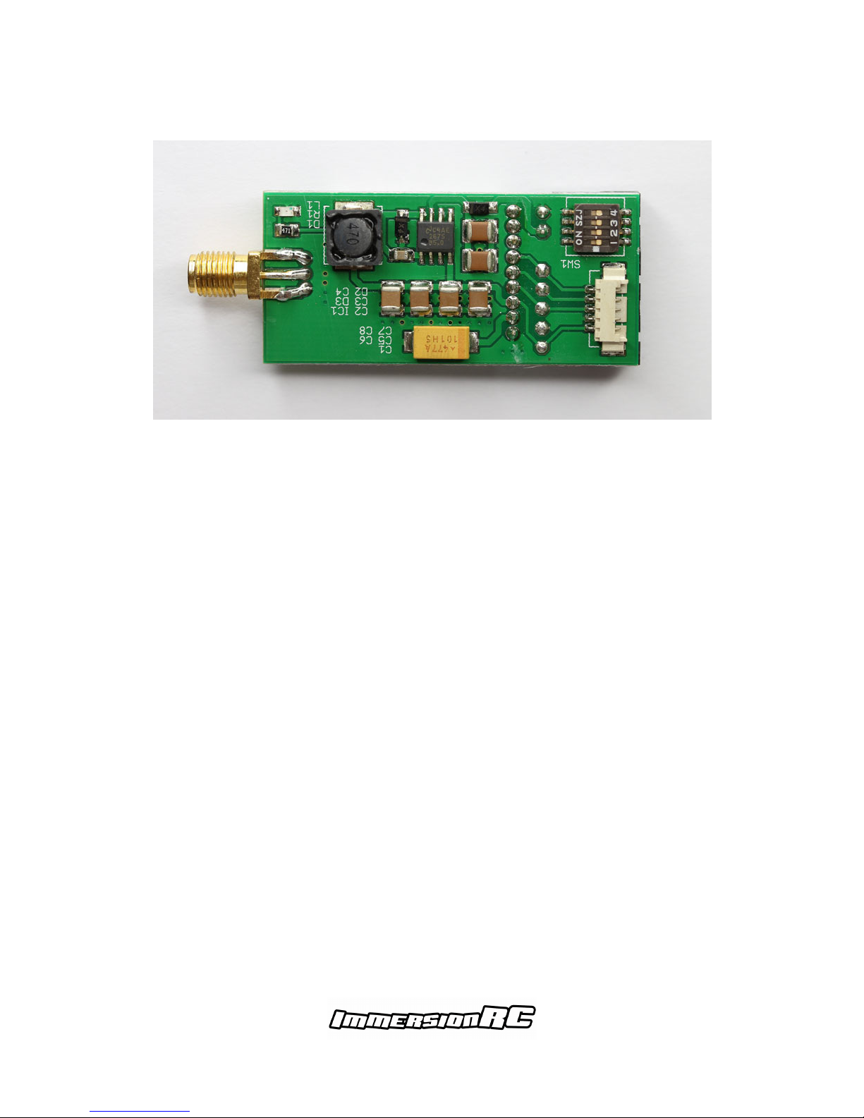
Fig 1. Top side of ImmersionRC 25mW 5.8GHz audio/video transmitter.
Center left > SMA female connector, connect your antenna here.
Top right > 5-pin Molex SL, audio/video input, 5V output.
Bottom right > 2-pin Molex SL, battery input, 6-25V DC.
www.immersionrc.com info@immersionrc.com
2
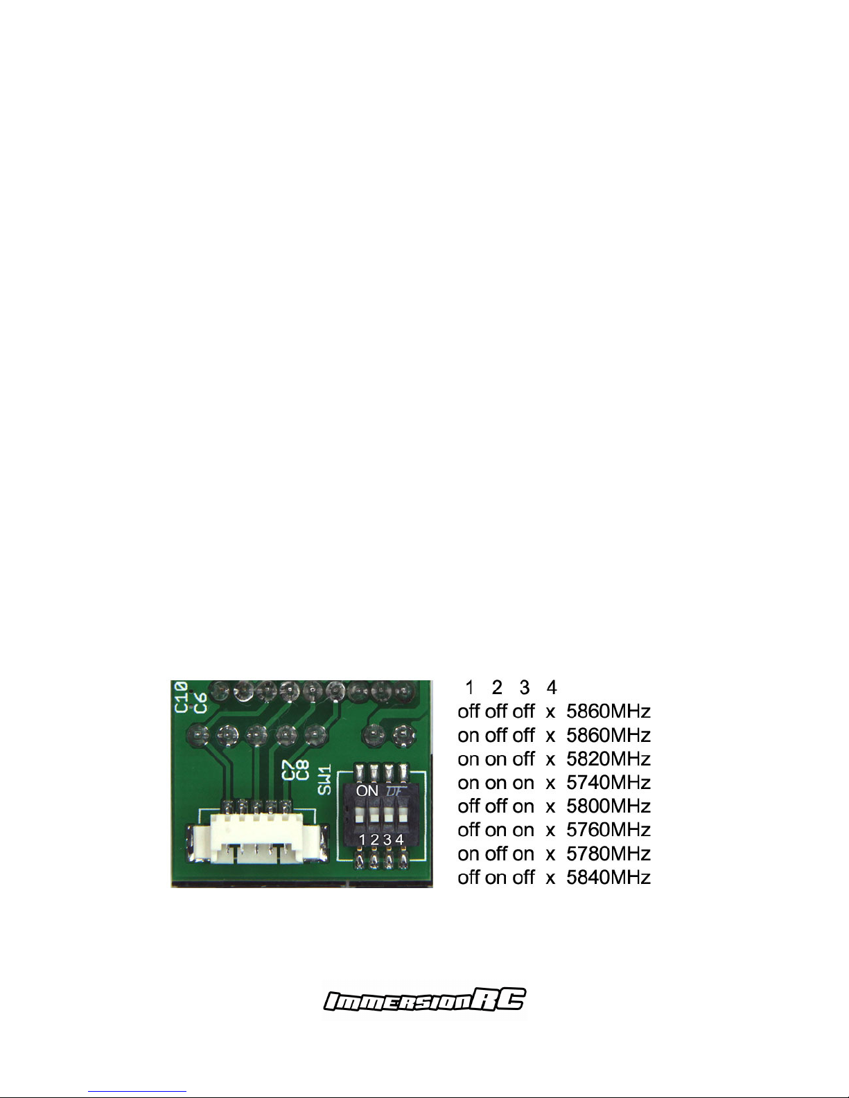
Fig 2. Bottom side of ImmersionRC 25mW 5.8GHz audio/video transmitter.
Center left > SMA female connector, connect your antenna here.
Top right > Dipswitch for settings channel frequency.
Bottom right > 5-pin Molex Picoblade, audio/video input, 5V output.
Please refer to the labeling on the sticker for the correct pin out for connecting your
power supply and camera or audio/video source to the audio/video input.
Battery input
BATT > Positive pole (+) on battery, usually RED
GND > Negative pole (-) on battery, usually BLACK
Audio/video input, 5V output
AUDR > Right audio channel
AUDL > Left audio channel
VID > Video input
GND > Negative pole - of battery and/or GND of video signal
5V out > 5V output, 300mA max.
Please note that the minimum supply voltage required is 6V and the maximum is 25V.
Do not opt to run your audio/video transmitter off of a regulated output of a BEC or
similar switching or linear regulator, the audio/video transmitter is designed to be
connected to your main flight battery directly.
The 5V output is NOT to be used as an input, it is an output only! Connecting this output
to another power supply, regardless of voltage, will render the audio/video transmitter
defective. The 5V output is designed to power a 5V camera directly, or, when used with
our 12V step-up, a 12V camera directly. The maximum power it can supply is 300mA,
hence this output CANNOT be used to power HD cameras such as the GoPro as they
have a much higher current draw.
www.immersionrc.com info@immersionrc.com
3
Instructions on use
A typical setup of the ImmersionRC 25mW 5.8GHz audio/video transmitter requires the
BATT-GND pins to be connected to the main flight pack directly, the audio/video input
typically requires VID-GND-5V out when a 5V camera is used.
NOTE: FatShark 5V cameras are fully compatible with ImmersionRC's transmitters and
are plug-and-play with the proper connector already fitted to the supplied cable.
NOTE: Due to the popularity of ImmersionRC's transmitters other brands have opted to
use the same connectors as ImmersionRC. In their infinite wisdom they unfortunately
have opted to not use the same, industry standard, ImmersionRC pin out. This can result
in significant damage to their, or ImmersionRC's, transmitters when used without
verifying the pin out. The same applies to the antenna connector, other manufacturers
have opted to use a RP-SMA antenna connector, which again is not compatible with the,
industry standard, SMA connector. Please always check and verify your connector pin
outs and type prior to use to prevent costly mistakes.
NOTE: In the images used in this manual the protective transparent shrink-wrap is
removed to be able to take clear photos, during use the shrink-wrap should NEVER be
removed as it protects the electronic components fitted to the PCB and safeguards the
transmitter from accidental short-circuits when in close contact with metallic or
conductive (carbon fiber) surfaces. I.e. always leave the shrink-wrap on, do NOT take it
off.
Channel frequencies
The frequency of the channel in the 5.8GHz band the audio/video transmitter transmits
on is set by a total of three (3) dipswitches on the transmitter. The 4th dipswitch is not
used for channel selection, hence its position doesn't matter. Please refer to the below
noted image for the channel frequencies and corresponding dipswitch settings:

www.immersionrc.com info@immersionrc.com
4
Notes on proper use of the audio/video transmitter
•Donotruntheaudio/videotransmitterwithoutasuitable antenna connected.
•DoNOTremovetheprotectiveoutershrink-wrap.
•Makesurethere'splentyofairflowoverthetransmitter for cooling.
•Makesuretheantennaisproperlyfittedandwon'tcome loose during use.
•Donotrunthetransmitteroffofaregulatedpower supply
-
Notes on troubleshooting the audio/video transmitter
•Novideo,blackscreen>capstilloncameralens,GND not connected on video.
•Poorrange,dropouts>RP-SMAantennafitted,LHCP/RHCP antennas mixed.
•NoLED>5Voutputshortedorexcessivepowerdrawfrom 5V output.
•Huminaudio>groundloop,multipleGNDwiresconnected.
•Snowyimage,black/white>wrongchannelselected.
•Dimensionalvortexcreated>reversepolarityonbattery input.
Regulatorynotice
The use of this product may be prohibited in your country/region/state, please verify that
the RF output power and frequencies used by this transmitter comply with local rules
and regulations, this product may require a license to operate.
Warranty
For warranty claims or repair requests please consult the retailer that you purchased this
product from, they will be able to help you with your warranty claim or repair request.
Package contents
The ImmersionRC 25mW 5.8GHz audio/video transmitter is shipped with the following
items:
1pcs - ImmersionRC 25mW 5.8GHz audio/video transmitter.
1pcs - Linear polarized SMA male articulating, straight 5.8GHz antenna.
1pcs - Cable, featuring a Molex SL 2-pin female plug to JST 2-pin male header.
1pcs - Cable, featuring a Molex SL 5-pin female plug to bare wire ends.
1pcs - ImmersionRC sticker.
Directionsonsafety
ImmersionRC advocates the safe use of their products, always make sure you
equipment is in proper working order, is checked prior to every flight and that your are
familiar and respect the equipment's capabilities and limitations. Do NOT fly recklessly,
do NOT fly near airports, freeways, towns, people, etc, basically anywhere were a
equipment failure or pilot error can result in injury or damage to people and/or property.
Manual rev2.0, ImmersionRC Limited - July 7th 2014.
Table of contents
Other ImmersionRC Extender manuals


