netsys NV-202G User manual

N
N
NV
V
V-
-
-2
2
20
0
02
2
2G
G
G
2
2
2G
G
Gi
i
ig
g
ga
a
a
L
L
LA
A
AN
N
N
o
o
ov
v
ve
e
er
r
r
V
V
VD
D
DS
S
SL
L
L2
2
2
e
e
ex
x
xt
t
te
e
en
n
nd
d
de
e
er
r
r
w
w
wi
i
it
t
th
h
h
D
D
DI
I
IP
P
P
S
S
Sw
w
wi
i
it
t
tc
c
ch
h
h
U
U
US
S
SE
E
ER
R
R’
’
’S
S
S
A
A
AN
N
NU
U
UA
A
AL
L
L

2 x Giga Lan over VDSL2 extender USER’S MANUAL Ver. A3
1
Copyright
Copyright © 2023 by National Enhance Technology Corp. All rights reserved.
Trademarks
NETSYS is a trademar of National Enhance Technology Corp.
Other brand and product names are registered trademar s or trademar s of their respective holders.
Legal Disclaimer
The information given in this document shall in no event be regarded as a guarantee of conditions or characteristics. With respect
to any examples or hints given herein, any typical values stated herein and/or any information regarding the application of the
device, National Enhance Technology Corp. hereby disclaims any and all warranties and liabilities of any ind, including without
limitation warranties of non-infringement of intellectual property rights of any third party.
Statement of Conditions
In the interest of improving internal design, operational function, and/or reliability, NETSYS reserves the right to ma e changes to
the products described in this document without notice. NETSYS does not assume any liability that may occur due to the use or
application of the product(s) or circuit layout(s) described herein.
Maximum signal rate derived from IEEE Standard specifications. Actual data throughput will vary. Networ conditions and
environmental factors, including volume of networ traffic, building materials and construction, and networ overhead, lower actual
data throughput rate. Netsys does not warrant that the hardware will wor properly in all environments and applications, and ma es
no warranty and representation, either implied or expressed, with respect to the quality, performance, merchantability, or fitness for
a particular purpose. ake sure you follow in line with the environmental conditions to use this product.

2 x Giga Lan over VDSL2 extender USER’S MANUAL Ver. A3
2
Foreword: VDSL2 solution
Attention:
Be sure to read this manual carefully before using this product. Especially Legal Disclaimer, Statement
of Conditions and Safety Warnings.
NV-202G is a 2 x 10/100/1000Mbps LAN over VDSL2 extender, that provide an economical solution for point to point application. It is
compliant with ITU-T G.993.2 VDSL2 standard, and G.998.4 INP standard. NV-202G supports a maximum bandwidth up to 160Mbps
symmetric and G.INP in VDSL2 Profile (17a/30a band profile) solution, and also supports both Master (CO) and Slave (CPE) modes
selectable by DIP Switch, as well as support UPBO / DPBO/ G.INP for preventing noise disturbance, NV-202T is also support
vectoring function for Telecom requirements.
Since VDSL2 has the characteristic of higher bandwidth over shorter distances, the ideal architecture for Telecoms is to use fiber
optic lines as the bac bone and a VDSL2 line as the last mile into the home or office. With outstanding throughput, the NV-202G can
complement a fiber networ to offer the best solution for delivering Triple play (Video/Voice/Data) or point to point application.
Caution:
The NV-202G is for indoor applications only. This product does not have waterproof protection, please do not use in outdoor
applications.

2 x Giga Lan over VDSL2 extender USER’S MANUAL Ver. A3
3
Safety Warnings
For your safety, be sure to read and follow all warning notices and instructions before using the device.
DO NOT open the device or unit. Opening or removing the cover may expose you to dangerous high voltage points or other
ris s. ONLY qualified service personnel can service the device. Please contact your vendor for further information.
Use ONLY the dedicated power supply for your device. Connect the power to the right supply voltage (110V AC used for
North America and 230V AC used for Europe.
Place connecting cables carefully so that no one will step on them or stumble over them. DO NOT allow anything to rest on
the power cord and do NOT locate the product where anyone can wor on the power cord.
DO NOT install nor use your device during a thunderstorm. There may be a remote ris of electric shoc from lightning.
DO NOT expose your device to dampness, dust or corrosive liquids.
DO NOT use this product near water, for example, in a wet basement or near a swimming pool.
Connect ONLY suitable accessories to the device.
ake sure to connect the cables to the correct ports.
DO NOT obstruct the device ventilation slots, as insufficient air flow may harm your device.
DO NOT place items on the device.
DO NOT use the device for outdoor applications directly, and ma e sure all the connections are indoors or have waterproof
protection place.
Be careful when unplugging the power, because it may produce spar s.
Keep the device and all its parts and accessories out of the reach of children.
Clean the device using a soft and dry cloth rather than liquid or atomizers. Power off the equipment before cleaning it.
This product is recyclable. Dispose of it properly.

2 x Giga Lan over VDSL2 extender USER’S MANUAL Ver. A3
4
TABLE OF CONTENTS
COPYRIGHT ........................................................................................................................................................ 1
FOREWORD: VDSL2 SOLUTION ........................................................................................................................ 2
SAFETY WARNINGS ........................................................................................................................................... 3
CHAPTER 1. UNPACKING INFOR ATION ......................................................................................................... 6
1.1 Chec List ...................................................................................................................................................................................... 6
CHAPTER 2. INSTALLING THE LAN EXTENDER .............................................................................................. 7
2.1 Hardware Installation ...................................................................................................................................................................... 7
2.2 Pre-installation Requirements ........................................................................................................................................................ 7
2.3 General Rules ................................................................................................................................................................................ 8
2.4 Connecting the LAN Extender ........................................................................................................................................................ 9
2.5 Connecting the RJ-11 / RJ-45 Ports ............................................................................................................................................. 10
2.6 NV-202G Application .................................................................................................................................................................... 12

2 x Giga Lan over VDSL2 extender USER’S MANUAL Ver. A3
5
CHAPTER 3. HARDWARE DESCRIPTION ........................................................................................................ 13
3.1 Front Panel ................................................................................................................................................................................... 14
3.2 Front Indicators ............................................................................................................................................................................ 15
3.3 Rear Panel ................................................................................................................................................................................... 16
APPENDIX A: CABLE REQUIREMENTS ........................................................................................................... 22
APPENDIX B: PRODUCT SPECIFICATION ....................................................................................................... 24
APPENDIX C: DIN-RAIL MOUNT INSTALLATION.............................................................................................. 27
APPENDIX D: TROUBLESHOOTING ................................................................................................................ 28
APPENDIX E: COMPLIANCE INFORMATION ................................................................................................... 35
APPENDIX F: PERFOR ANCE TABLE ............................................................................................................ 38
WARRANTY ....................................................................................................................................................... 40
CHINESE SJ/T 11364-2014 ................................................................................................................................ 41
2 x Giga Lan over VDSL2 extender USER’S MANUAL Ver. A3
6
CHAPTER 1.
UNPACKING INFOR ATION
1.1 Check List
Carefully unpac the pac age and chec its contents against the chec list.
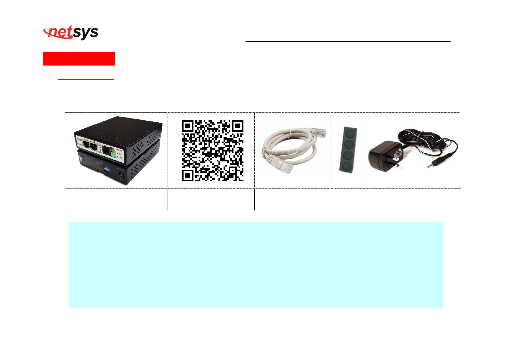
Package Contents:
1 x NV-202G 1 x QR code for user’s
manual hyperlin .
Accessory:
1 x Ehternet Cable, 4 x Rubber Feet , 1 x DC12V Adapter
Notes:
1. Please inform your dealer immediately for any missing or damaged parts. If possible, retain the carton including the
original pac ing materials. Use them to repac the unit in case there is a need to return for repair.
2. If the product has any issue, please contact your local vendor.
3. Do not use sub-standard power supply. Before connecting the power supply to the device, be sure to chec
compliance with specifications. The NV-202G uses a DC12V/1A power supply.
4. The power supply included in the pac age is commercial-grade. Do not use in industrial-grade applications.
5. If you would li e to use the telephone, please purchase a suitable external splitter and install to the line port.
6. Please loo for the QR code on the bottom of the product, the user can launch the QR code scanning program to
scan and download the user’s manual electronic format file. Above QR code icon is for reference.

2 x Giga Lan over VDSL2 extender USER’S MANUAL Ver. A3
7
Chapter 2. Installing the LAN Extender
2.1 Hardware Installation
This chapter describes how to install the bridge and establish the networ connections. The NV-202G may be installed
on any level surface (e.g. a table or shelf or rail). However, please ta e note of the following minimum site requirements
before one begin.
2.2 Pre-installation Requirements
Before you start the actual hardware installation, ma e sure you can provide the right operating environment, including
power requirements, sufficient physical space, and proximity to other networ devices that are to be connected.
Verify the following installation requirements:
Power requirements: DC 12V /1A power source.
The bridge should be located in a cool dry place, with at least 10cm/4in of space at the front and bac for
ventilation.
Place the bridge away from direct sunlight, heat sources, or areas with a high amount of electromagnetic
interference.
Chec if the networ cables and connectors needed for installation are available.
Do not install phone lines strapped together with AC power lines, or telephone office line with voice signal.
Avoid installing this device with radio amplifying station nearby or transformer station nearby.

2 x Giga Lan over VDSL2 extender USER’S MANUAL Ver. A3
8
2.3 General Rules
Before ma ing any connections to the bridge, please note the following rules:
Ethernet Port (RJ-45)
All networ connections to Ethernet port must be made using Category 5 UTP/STP or above for
100/1000Mbps, Category 3, 4 UTP for 10Mbps.
No more than 100 meters of cabling may be use between Ethernet switch or HUB and an end node.
VDSL2 Port (RJ-11)
All networ connections to the RJ-11port must use 24~26 gauge with twisted pair phone wiring.
We do not recommend the use of the telephone line 28 gauge or above.
The RJ-11 connectors have six positions, two of which are wired. The router uses the center two pins. The
pin out assignment for these connectors is presented below.
Please note that the line port is no polarity, therefore user can reverse the two wires of the phone cable
when installed.
RJ-11 Pin out Assignments
Pin# NE ONIC FUNCTION
1 NC Unused
2 NC Unused
3 DSL Used
4 DSL Used
5 NC Unused
6 NC Unused_

2 x Giga Lan over VDSL2 extender USER’S MANUAL Ver. A3
9
External Splitter
NV-202G support both POTS and ISDN PBX, and depending on using an external splitter, ma e sure that you
are using one that is compatible with the interface you want to use.
2.4 Connecting the LAN Extender
The bridge has two Ethernet ports which support connection to Ethernet operation. The devices attached to these
ports must support auto-negotiation or 10Base-T or 100/1000Base-TX unless they will always operate at half duplex.
Use any of the Ethernet ports to connect to devices such as Monitor system, Server, Switch, bridge or router.
Notes:
1. The RJ11 Line port is used to connect the telephone that is connected to VDSL2 Master (CO) and Slave (CPE)
both NV-202G (Point-to-Point solution).
2. The Master (CO) mode device must be interconnected to the Slave (CPE) mode device over copper wire. Please
note both NV-202G interconnecting cannot config the same mode, please confirm the DIP switch config before
both NV-202G interconnecting.

2 x Giga Lan over VDSL2 extender USER’S MANUAL Ver. A3
10
2.5 Connecting the RJ-11 / RJ-45 Ports
The line port has 2 connectors: RJ-45 and terminal bloc . It is used to connect with NV-202G(Master / CO) using a single pair
phone cable to NV-202G(Slave / CPE) bridge side (point to point solution). Ta e note that NV-202G line port RJ-11 and terminal
bloc cannot be used at the same time. Either RJ-11 port is connected or terminal bloc is connected using straight connection
(Figure 2.4) or cross-over connection (Figure 2.5)
Figure 2.4 NV-202G line ports straight connection
Figure
2.5
NV
-
202
G
line ports crossover connection
When inserting a RJ-11 plug, ma e sure the tab on the plug clic s into position to ensure that it is properly seated.
Do not plug a RJ-11 phone jac connector into the Ethernet port (RJ-45 port). This may damage the bridge. Instead, use only
twisted-pair cables with RJ-45 connectors that conform to Ethernet standard.

2 x Giga Lan over VDSL2 extender USER’S MANUAL Ver. A3
11
Notes:
1. Be sure each twisted-pair cable (RJ-45 ethernet cable) does not exceed 100 meters (333 feet).
2. We advise using Category 5~7 UTP/STP cables for Cable bridge or Bridge connections to avoid any confusion
or inconvenience in the future when you attached to high bandwidth devices.
3. Use 24 ~ 26 gauge twisted pair phone wiring, we do not recommend 28 gauge or above.
4. Be sure the phone cable has been installed before NV-202G is powered on.
2 x Giga Lan over VDSL2 extender USER’S MANUAL Ver. A3
12
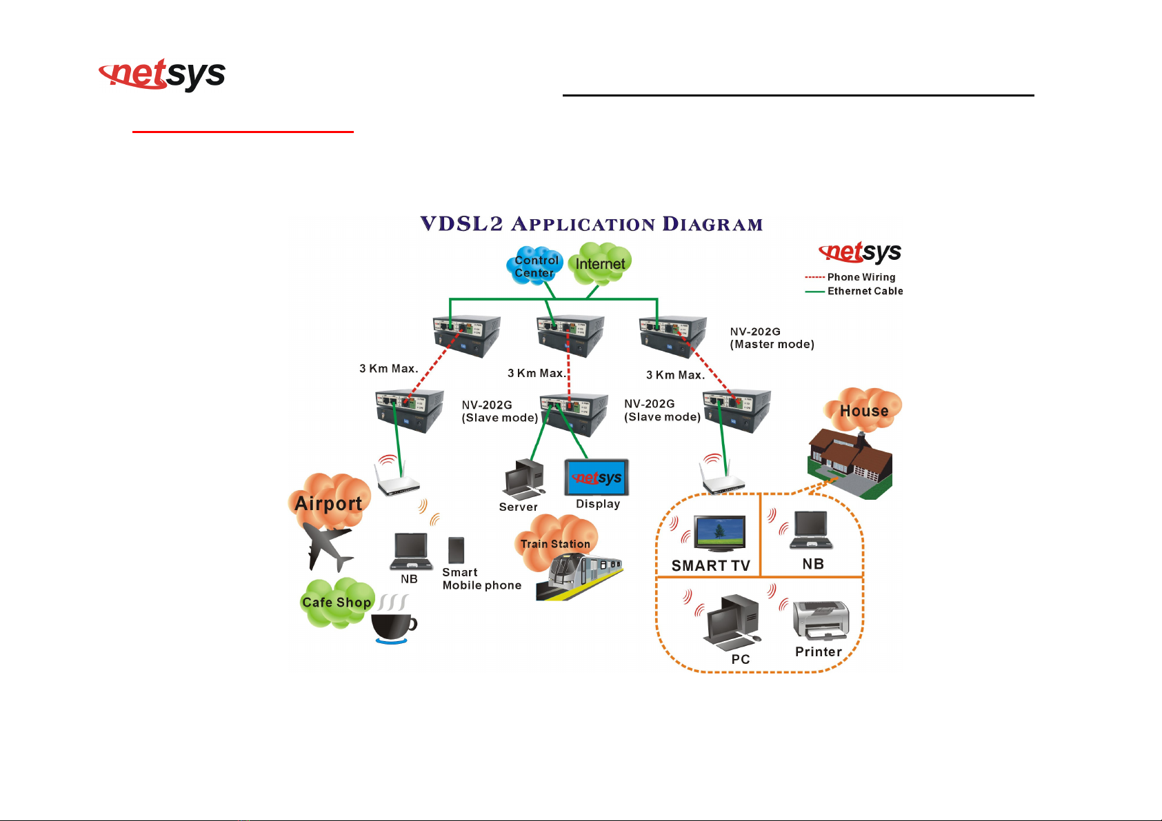
2.6 NV-202G Application
The bridge’s line port supports 100Mbps for data service across existing phone wiring. It is easy-to-use which do not request
installation of additional wiring. Every modular phone jac in the home can become a port on the LAN. Networ ing devices can be
installed on a single telephone wire that can be installed within suitable distance (depends on speed) (Figure 2.6)
Figure 2.6 NV-202G point to point applications
2 x Giga Lan over VDSL2 extender USER’S MANUAL Ver. A3
13
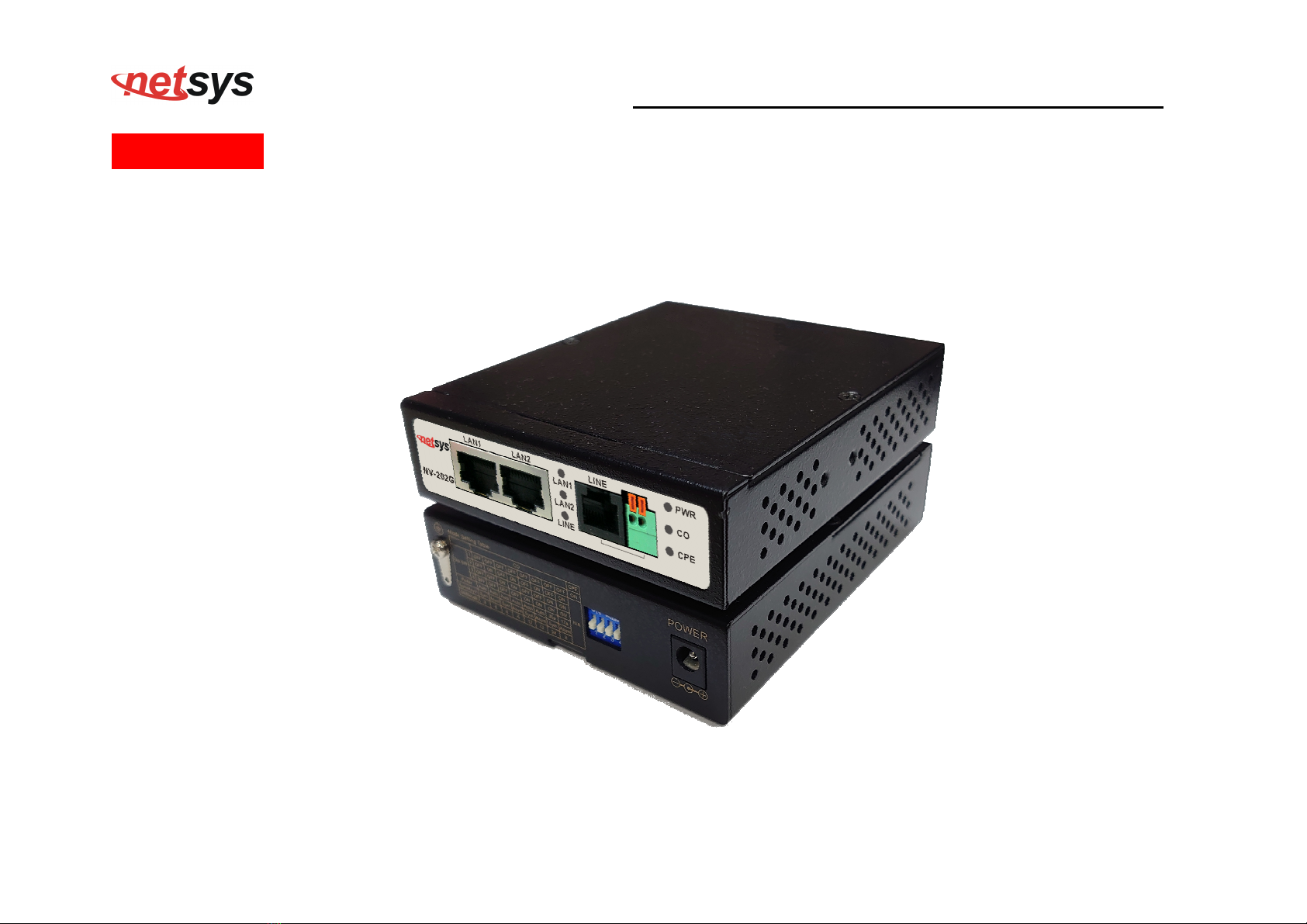
Chapter 3. Hardware Description
This section describes the important parts of the LAN Extender. It features the front panel and rear panel.
NV-202G Outward
2 x Giga Lan over VDSL2 extender USER’S MANUAL Ver. A3
14
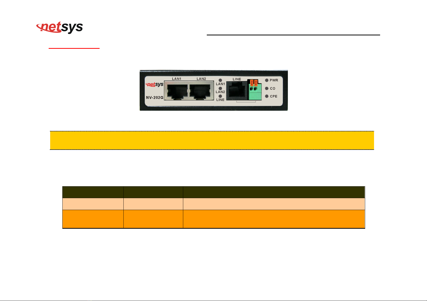
3.1 Front Panel
The front panel provides a simple interface monitoring of the LAN Extender. (Figure 3.1)
Figure 3.1 Front Panel
Tip:
At a quick glance of the front panel, it is easy to determine if it has Ethernet signal from its RJ-45 port and
if there is vdsl line signal on RJ-11 port.
And the table shows the description. (Table 3-1)
Table 3-1 Description of the bridge front connectors
Connectors Type Description
LAN1 / LAN2 RJ-45 For connecting to an Ethernet equipped device.
Line RJ-11/Terminal Bloc
For connecting to LAN Extender. (Do not use RJ11 and Terminal
Bloc at the same time.)
2 x Giga Lan over VDSL2 extender USER’S MANUAL Ver. A3
15
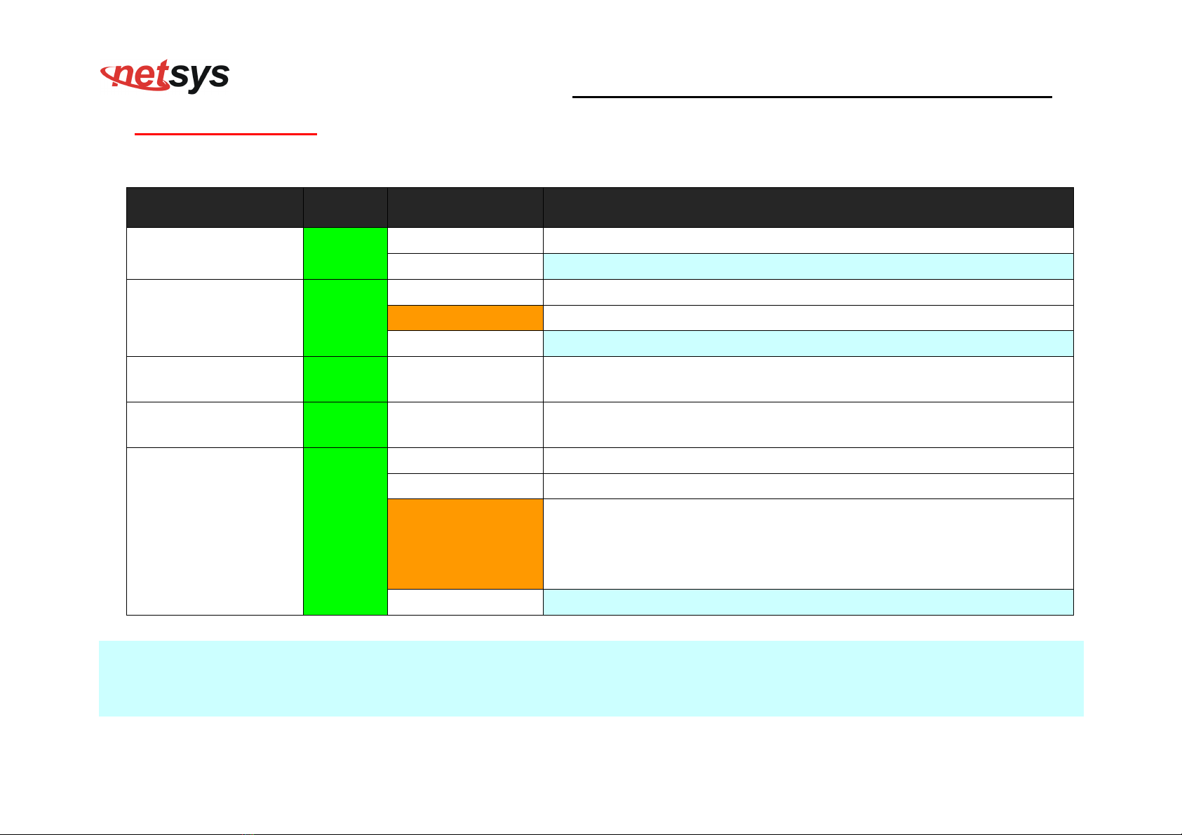
3.2 Front Indicators
The bridge has Eight LED indicators. The following Table shows the description. (Table 3-2)
Table 3-2 LED Indicators Description and Operation
LED Color Status Descriptions
PWR
(Power LED) Green On(Steady) Lights to indicate that the VDSL2 bridge had power
Off The device is not ready or has malfunctioned.
LAN 1-2
(Ethernet LED) Green
On(Steady) The device has a good Ethernet connection.
Blin ing The device is sending or receiving data.
Off The LAN is not connected.
CO LED
(Master mode) Green On(Steady) Indicate the NV-202G is configured in aster (CO) mode.
CPE LED
(Slave mode) Green On(Steady) Indicate the NV-202G is configured in Slave (CPE) mode.
LINE
(VDSL LINK LED) Green
On(Steady) The Internet or networ connection is up.
Blin ing slowly The Master (CO) device is detecting with Slave (CPE) device.
Blin ing fastly
1. The Master (CO) device has been handsha ing a Slave (CPE)
device and ready to connect.
2. LED indicator is shown sending or receiving data after lin
established.
Off The Internet or networ connection is down or has malfunctioned.
Note:
It is normal for the connection between two bridged to ta e up to 3 minutes, due to NV-202G to establish a lin mechanism in
auto-negotiation, that detects and calculates Master (CO) and Slave (CPE) both PBO and PSD level, noise levels and other
arguments for getting a better connection.
2 x Giga Lan over VDSL2 extender USER’S MANUAL Ver. A3
16
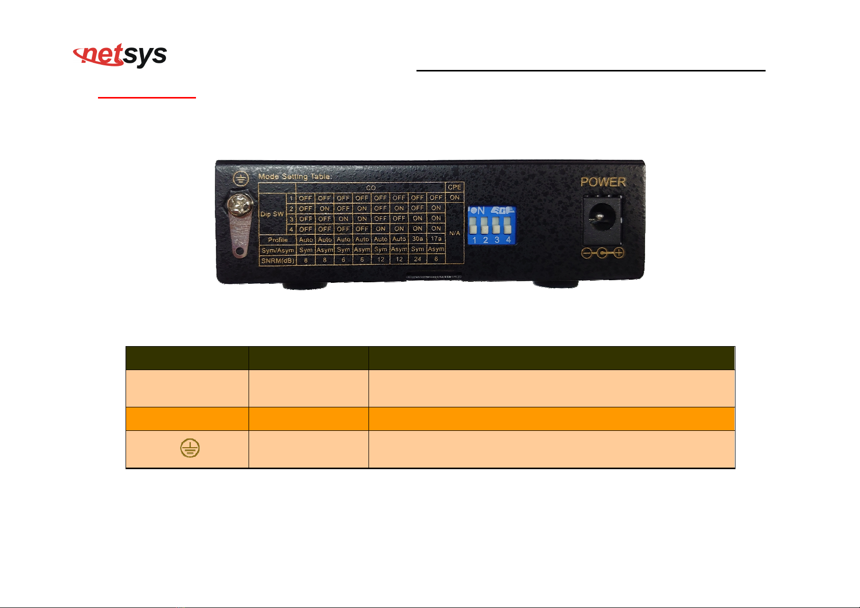
3.3 Rear Panel
The following figure shows the rear panel. (Figure 3.2)
Figure 3.2 Rear Panel
And the table shows the description. (Table 3-3)
Table 3-3 Description of the bridge front connectors
Connectors Type Description
Power DC Power Jac External Power Adapter: Input: AC 100~240Volts/50~60Hz
Output: DC 12V/1A
DIP Switch 4 Pins DIP Switch Provide 4 selectable transmission modes.
Ground Ground lug Please connect the ground lug to the earth ground. To prevent an
electric shoc when user touches.
2 x Giga Lan over VDSL2 extender USER’S MANUAL Ver. A3
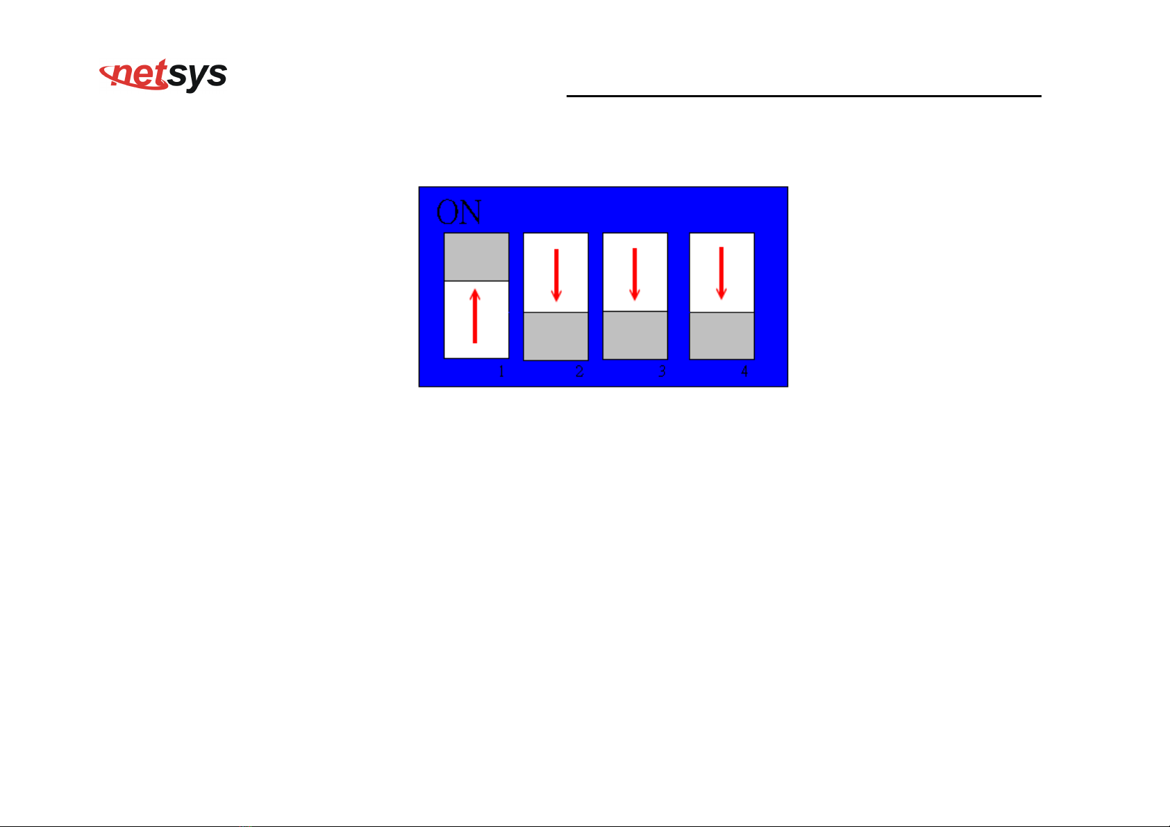
17
The following figure shows the DIP switch connection. By switching the transmission modes, you can obtain a best transmission
mode to suit with phone line quality or distance or connectivity. (Figure 3.3)
Figure 3.3 DIP switch setting

2 x Giga Lan over VDSL2 extender USER’S MANUAL Ver. A3
18
The following is table of DIP Switch configuration. (Table 3-4)
Below table clarify the settings of 9 different NV-202G function modes.
DIP Switch on rear panel
Config ode Description
PIN1
PIN2
PIN3
PIN4
OFF
OFF
OFF
OFF
Sy-Auto I_8/2 (SNR 8/8) Symmetric Auto, ax. Interleave=8, in. INP=2,
SNR =8 (Default)
OFF
ON OFF
OFF
NSy-Auto I_8/2 (SNR 8/8) non symmetric Auto, ax. Interleave=8, in. INP=2,
SNR =8
OFF
OFF
ON OFF
Sy-Auto I_8/2 (SNR 6/6) Symmetric Auto, ax. Interleave=8, in. INP=2,
SNR =6
OFF
ON ON OFF
NSy-Auto I_8/2 (SNR 6/6) Non symmetric Auto, ax. Interleave=8, in. INP=2,
SNR =6
OFF
OFF
OFF
ON Sy-Auto G.INP_17/2/41 (SNR
12/12)
Symmetric Auto, enable G.INP, enable re-transmission,
SNR =12
OFF
ON OFF
ON NSy-Auto G.INP_17/2/41 (SNR
12/12)
non symmetric Auto, enable G.INP, enable re-transmission,
SNR =12
OFF
OFF
ON ON Sy-30a-D2.2 G.INP_17/2/41 (Rate
20/20) (SNR 24/24)
Symmetric 30a, disable 0~2.2 Hz, enable G.INP, enable re-
transmission, max. Line rate=20 bps, SNR =24
OFF
ON ON ON Annex-A-17a-eu32_I-8/2 (SNR 6/6)
17A Annex A Eu32, ax. Interleave=8, in. Inp=2,
SNR =6
ON NA NA NA Slave ode (CPE) Switching to Slave mode (CPE)
Please power off NV-202G, before ma ing any transmission mode configuration.

2 x Giga Lan over VDSL2 extender USER’S MANUAL Ver. A3
19
PIN1:
ON: CPE Mode or call slave side, usually the CPE side will be located at factory, weather station, MRT and train station as the
long reach data transmission.
OFF: CO Mode or call Master side, usually the CO device will be located at the data enter of enterprise to lin to the bac bone.
Tip:
When the NV-202G operates at a CPE(Slave) mode, the DIP switch 2, 3, 4 has no function.
PIN2: band selection, please refer to table 3-4
PIN3: band selection, please refer to table 3-4
PIN4: band selection, please refer to table 3-4
Table of contents
Other netsys Extender manuals


