Bodenhof 4, 6014 Luzern (Switzerland)
4x16mm
7x40mm
M6x12mm
80 mm
80 mm
1×
EVOline®
Circle80 Monitor plate
Bedienungs- und Montageanleitung
Operating and assembly instructions
Instructions d‘utilisation et d‘installation
Schulte Elektrotechnik GmbH & Co. KG
Jüngerstraße 21
D-58515 Lüdenscheid
Telefon +49 23 51 / 94 81-0
Telefax +49 23 51 / 4 26 58
Email info@schulte.com
www.evoline.com
1×
Lieferumfang | Box Contents | Contenu de la livraison
Stand 03/2021
Technische
Änderungen
vorbehalten
4040 2110 0000
Die aktuellen Bedienungs- und Montageanleitungen
nden Sie auf unserer Homepage
www.evoline.com/service/downloads.
The current operating and installation instructions can be
found on our homepage
www.evoline.com/service/downloads.
Les instructions d'utilisation et d'installation sont dis-
ponibles sur notre page d'accueil
www.evoline.com/service/downloads.
Maße | Dimensions | Dimensions
Monitorfußplatte | Monitor base plate
Maße | Dimensions | Dimensions
Circle 80
7,5 mm
92 mm
124 mm
91,6 mm
10,5 mm
ø < 65 mm
184 mm
58 mm
79 mm
48,5 mm
54 mm
min. 10 mm
Einbauanleitung | Installation Instructions | Guide d‘installation
12 3
456
7
Max. Drehmoment
Max. Torque
Max. Couple
M =0,33 Nm
TX 8 8 (optional) 9
10
> 65 mm
> 45 mm
> 65 mm
> 65 mm
Bohrdurchmesser (x) abhängig von Monitorhalterung
Drilling diameter (x) depending on monitor bracket
Diamètre de perçage (x) selon le support du moniteur
x mm
Beispielmontage (abhängig von Monitorhalterung)
Example mounting (depending on monitor bracket)
Exemple de montage (selon le support du moniteur)
11
5,5 mm
80 mm
80 mm
1×
EVOline®
Circle80 Monitor plate
Bedienungs- und Montageanleitung
Operating and assembly instructions
Instructions d‘utilisation et d‘installation
Schulte Elektrotechnik GmbH & Co. KG
Jüngerstraße 21
D-58515 Lüdenscheid
Telefon +49 23 51 / 94 81-0
Telefax +49 23 51 / 4 26 58
Email info@schulte.com
www.evoline.com
1×
Lieferumfang | Box Contents | Contenu de la livraison
Stand 03/2021
Technische
Änderungen
vorbehalten
4040 2110 0000
Die aktuellen Bedienungs- und Montageanleitungen
nden Sie auf unserer Homepage
www.evoline.com/service/downloads.
The current operating and installation instructions can be
found on our homepage
www.evoline.com/service/downloads.
Les instructions d'utilisation et d'installation sont dis-
ponibles sur notre page d'accueil
www.evoline.com/service/downloads.
Maße | Dimensions | Dimensions
Monitorfußplatte | Monitor base plate
Maße | Dimensions | Dimensions
Circle 80
7,5 mm
92 mm
124 mm
91,6 mm
10,5 mm
ø < 65 mm
184 mm
58 mm
79 mm
48,5 mm
54 mm
min. 10 mm
Einbauanleitung | Installation Instructions | Guide d‘installation
12 3
456
7
Max. Drehmoment
Max. Torque
Max. Couple
M =0,33 Nm
TX 8
8 (optional) 9
10
> 65 mm
> 45 mm
> 65 mm
> 65 mm
Bohrdurchmesser (x) abhängig von Monitorhalterung
Drilling diameter (x) depending on monitor bracket
Diamètre de perçage (x) selon le support du moniteur
x mm
Beispielmontage (abhängig von Monitorhalterung)
Example mounting (depending on monitor bracket)
Exemple de montage (selon le support du moniteur)
11
5,5 mm
80 mm
80 mm
1×
EVOline®
Circle80 Monitor plate
Bedienungs- und Montageanleitung
Operating and assembly instructions
Instructions d‘utilisation et d‘installation
Schulte Elektrotechnik GmbH & Co. KG
Jüngerstraße 21
D-58515 Lüdenscheid
Telefon +49 23 51 / 94 81-0
Telefax +49 23 51 / 4 26 58
Email info@schulte.com
www.evoline.com
1×
Lieferumfang | Box Contents | Contenu de la livraison
Stand 03/2021
Technische
Änderungen
vorbehalten
4040 2110 0000
Die aktuellen Bedienungs- und Montageanleitungen
nden Sie auf unserer Homepage
www.evoline.com/service/downloads.
The current operating and installation instructions can be
found on our homepage
www.evoline.com/service/downloads.
Les instructions d'utilisation et d'installation sont dis-
ponibles sur notre page d'accueil
www.evoline.com/service/downloads.
Maße | Dimensions | Dimensions
Monitorfußplatte | Monitor base plate
Maße | Dimensions | Dimensions
Circle 80
7,5 mm
92 mm
124 mm
91,6 mm
10,5 mm
ø < 65 mm
184 mm
58 mm
79 mm
48,5 mm
54 mm
min. 10 mm
Einbauanleitung | Installation Instructions | Guide d‘installation
12 3
456
7
Max. Drehmoment
Max. Torque
Max. Couple
M =0,33 Nm
TX 8 8 (optional) 9
10
> 65 mm
> 45 mm
> 65 mm
> 65 mm
Bohrdurchmesser (x) abhängig von Monitorhalterung
Drilling diameter (x) depending on monitor bracket
Diamètre de perçage (x) selon le support du moniteur
x mm
Beispielmontage (abhängig von Monitorhalterung)
Example mounting (depending on monitor bracket)
Exemple de montage (selon le support du moniteur)
11
5,5 mm
80 mm
80 mm
1×
EVOline®
Circle80 Monitor plate
Bedienungs- und Montageanleitung
Operating and assembly instructions
Instructions d‘utilisation et d‘installation
Schulte Elektrotechnik GmbH & Co. KG
Jüngerstraße 21
D-58515 Lüdenscheid
Telefon +49 23 51 / 94 81-0
Telefax +49 23 51 / 4 26 58
Email info@schulte.com
www.evoline.com
1×
Lieferumfang | Box Contents | Contenu de la livraison
Stand 03/2021
Technische
Änderungen
vorbehalten
4040 2110 0000
Die aktuellen Bedienungs- und Montageanleitungen
nden Sie auf unserer Homepage
www.evoline.com/service/downloads.
The current operating and installation instructions can be
found on our homepage
www.evoline.com/service/downloads.
Les instructions d'utilisation et d'installation sont dis-
ponibles sur notre page d'accueil
www.evoline.com/service/downloads.
Maße | Dimensions | Dimensions
Monitorfußplatte | Monitor base plate
Maße | Dimensions | Dimensions
Circle 80
7,5 mm
92 mm
124 mm
91,6 mm
10,5 mm
ø < 65 mm
184 mm
58 mm
79 mm
48,5 mm
54 mm
min. 10 mm
Einbauanleitung | Installation Instructions | Guide d‘installation
12 3
456
7
Max. Drehmoment
Max. Torque
Max. Couple
M =0,33 Nm
TX 8 8 (optional) 9
10
> 65 mm
> 45 mm
> 65 mm
> 65 mm
Bohrdurchmesser (x) abhängig von Monitorhalterung
Drilling diameter (x) depending on monitor bracket
Diamètre de perçage (x) selon le support du moniteur
x mm
Beispielmontage (abhängig von Monitorhalterung)
Example mounting (depending on monitor bracket)
Exemple de montage (selon le support du moniteur)
11
5,5 mm
12
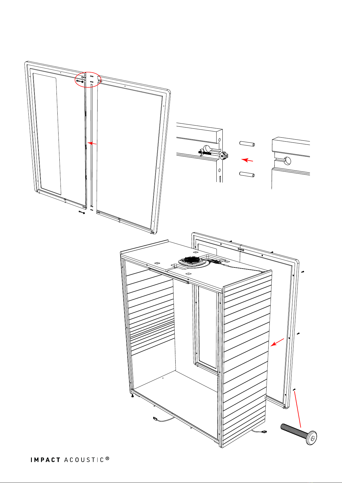
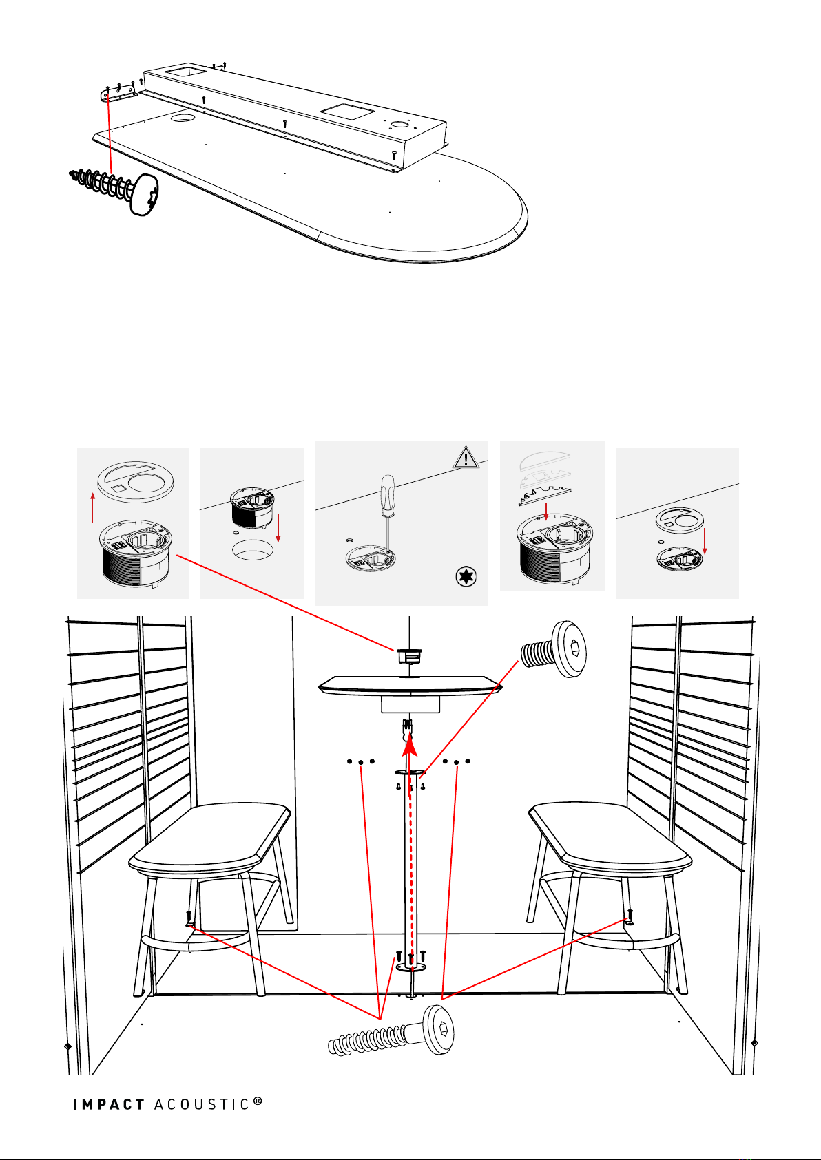
Screw the cable channel
and the two brackets
onto the table top.
13
Pull the cable through the column. Fasten the column with four 7x40mm screws.
Attach the table top to the table column with four M6x12mm screws. Connect
the table top to the back panel with six 7x40mm screws. Screw the benches onto
the floor with the 7x40mm screws. Carefully loosen the cover of the socket. Con-
nect the socket with the supply cable. Insert the socket into the hole. Align it and
tighten it. Place the insert and snap the cover back into place.