Impax IM-MMA140 User manual

EC DECLARATION OF CONFORMITY
The manufacturer of the product covered by this Declaration is.
NAP Brands Ltd.
Napier House, Unit 7, Corunna Court,
Warwick, United Kingdom CV34 5HQ
The manufacturer hereby declares that the machine as detailed in this declaration fulfils all the
relevant provisions of the Machinery Directive and other appropriate directives as detailed below.
The manufacture further declares that the machine as detailed in this declaration, where applicable,
fulfils the relevant provisions of the essential health and safety requirements.
The Directives covered by this Declaration are as detailed below
Product Details:
Description: Arc Welder
Model No: IM-MMA140
Brand Name: Impax
Name and address of technical documentation holder.
The technical documentation required to demonstrate that the product meets the requirements of
directive has been compiled and is available for inspection by the relevant enforcement authorities.
Signed: Print: Mark Shannon
Senior Quality Control Manager.
NAP Brands Ltd.
Napier House, Unit 7, Corunna Court, Warwick, United Kingdom CV34 5HQ
Date:.06.09.2013
98/37/EEC The Machinery Directive.
2006/95/EC. Low Voltage Equipment Directive.
2004/108/EC. Electromagnetic Compatibility Directive,
93/68/EC. The CE Marking Directive.
2002/95/EC. The Restriction of the Use of certain Hazardous Substances in Electrical Equipment
(RoHS) Directive
2002/96/EC as amended by 2003/108/EC The Waste Electrical and Electronic Equipment (WEEE)
Directive.
After sales support: Tel: 0844 264 2485 Website: www.impaxpowertools.com
??
And is in conformity with the applicable requirements of the following documents
IEC/EN 60974-1: 2012
EN60974-10

Always Read Instruction Manual
Retain for uture Reference
IM-MMA140
140A MMA WELDER

2
CERTIFICATE OF GUARANTEE
This product is guaranteed for a period of 1 Year, with effect from the date of purchase and applies
only to the original purchaser. This guarantee only applies to defects arising from, defective materials
and or faulty workmanship that become evident during the guarantee period only and does not
include consumable items. The manufacturer will repair or replace the product at their discretion
subject to the following. That the product has been used in accordance with the guidelines as
detailed in the product manual and that it has not been subjected to misuse, abuse or used for a
purpose for which it was not intended. That it has not been taken apart or tampered with in any way
whatsoever or has been serviced by unauthorised persons or has been used for hire purposes.
Transit damage is excluded from this guarantee, for such damage the transport company is
responsible. Claims made under this guarantee must be made in the first instance, directly to the
retailer within the guarantee period. Only under exceptional circumstances should the product be
returned to the manufacturer. In this case it shall be the consumer’s responsibility to return the
product at their cost ensuring that the product is adequately packed to prevent transit damage and
must be accompanied with a brief description of the fault and a copy of the receipt or other proof of
purchase. The manufacturer shall not be liable for any special, exemplary, direct, indirect, incidental,
or consequential loss or damage under this guarantee. This guarantee is in addition to and does not
affect any rights, which the consumer may have by virtue of the Sale of Goods Act 1973 as
amended 1975 and 1999.
INTRODUCTION
Thankyou for purchasing this product which has passed through our extensive quality assurance
process. Every care has been taken to ensure that it reaches you in perfect condition. However, in
the unlikely event that you should experience a problem, or if we can offer any assistance or advice
please do not hesitate to contact our customer care department. or details of your nearest
customer care department please refer to the telephone numbers at the back of this manual.
Safety First
Before attempting to operate this product the following basic safety precautions should always be
taken to reduce the risk of fire, electric shock and personal injury. It is important to read the
instruction manual to understand the application, limitations and potential hazards associated with
this product.
HELPLINE & SPARE PARTS
In the unlikely event of a defect occurring please contact our Helpline.
Office hours: Monday - riday 9:00am – 5:30pm.
Telephone Number 0844 264 2485

3
SAFETY INFORMATION
Before attempting to operate the machine, it is
essential that you read this manual thoroughly
and carefully follow all instructions given. In
doing so you will ensure the safety of yourself
and that of others around you, and you can also
look forward to the welder giving you long and
satisfactory service.
Important
Warning! If you have no welding experience, we
recommend you seek training from an
experienced person.
Caution: The pages of this manual are restricted
to the basic safe use of an MMA (Manual Metal
Arc) welding power supply and very basic
welding technique. We recommend you
purchase a good quality publication on welding
or if you have internet access visit one of the
numerous welding related web sites to be able
to use the welding power supply to its full
potential.
The electrodes used in an MMA welding are
many and varied. You are advised to seek advice
from your local welding equipment supplier for
the correct selection of wire electrode for the
work being performed.
THE QUALITY OF ANY WELDED JOINT IS
DEPENDANT ON THE PREPARATION OF THE
JOINT THE SELECTION OFTHE CORRECT
WIRE ELECTRODE AND THE S ILL AND
EXPERIENCE OF THE WELDER.
General Welding Safety
The Workshop Environment
Housekeeping is extremely important to avoid
injury from slips, trips and falls, damage to
equipment and fire. The work area should be
kept clean and tidy at all times. Combustible
materials must not be discarded or stored in the
vicinity of the welding area.
Avoid using your welder in the vicinity of:
a) other supply cables, control cables, signalling
and telephone cables; above, below and
adjacent to the welding equipment;
b) radio and television transmitters and
receivers;
c) computer and other control equipment;
d) safety critical equipment, e.g. guarding of
industrial equipment;
e) pacemakers and hearing aids etc.;
f) equipment used for calibration or
measurement;
g) other equipment in the environment. The user
shall ensure that other equipment being used
in the environment is compatible. This may
require additional protection measures;
It may be possible to avoid the above by
changing the time of day that welding or other
activities are to be carried out.
The size of the surrounding area to be
considered will depend on the structure of the
building and other activities that are taking
place. The surrounding area may extend beyond
the boundaries of the premises.
Electrical Safety
As one of the principal dangers from welding
operations is an electric shock, from the live
parts of the welding circuit (the wire electrode
torch and the work piece), the following
practices are recommended.
Shock Prevention
Exposed live conductors or other bare metal in
the welding circuit, or in unearthed, electrically-
LIVE equipment can fatally shock a person
whose body becomes a conductor. DO NOT
STAND, SIT, LIE, LEAN ON, OR TOUCH a wet
surface when welding, without suitable
protection.
Protection for Wearers of Pacemakers
Magnetic fields from high currents can affect
pacemaker operation. Persons wearing
electronic life support equipment (pacemaker)
should consult with their doctor before going
near arc welding, gouging, or spot welding
operations.
To Prevent Against Shock
Keep body and clothing dry. Never work in
damp area without adequate insulation against
electrical shock. Stay on a dry duckboard, or
rubber mat when dampness or sweat can not
be avoided.

SAFETY INFORMATION
Sweat, sea water, or moisture between body
and an electrically LIVE part - or earthed metal -
reduces the body surface electrical resistance,
enabling dangerous and possibly lethal currents
to flow through the body.
Earthing the Equipment
When arc welding equipment is earthed
according to the National Electrical Code, and
the workpiece is earthed, a voltage may exist
between the electrode and any conducting
object.
Examples of conducting objects include, but are
not limited to, buildings, electrical tools, work
benches, welding power source cases,
workpieces, etc.
Never touch the electrode and any metal object
unless the welding power source is off. When
installing, connect the frames of each unit such
as welding power source, control, work table,
and water circulator to the building earth.
Conductors must be adequate to carry earth
currents safely. Equipment made electrically
LIVE by stray current may shock, possibly
fatally. Do NOT EARTH to electrical conduit, or
to a pipe carrying ANY gas or a flammable liquid
such as oil or fuel.
Electrode Holders
ully insulated electrode holders should be
used. Do NOT use holders with protruding
screws or with any form of damage.
Connectors
ully insulated lock-type connectors should be
used to join welding cable.
Cables
requently inspect cables for wear, cracks and
damage. IMMEDIATELY REPLACE those with
excessively worn or damaged insulation to avoid
possibly lethal shock from bared cable. Cables
with damaged areas may be taped to give
resistance equivalent to original cable. Keep
cable dry, free of oil and grease, and protected
from hot metal and sparks.
Terminals And Other Exposed Parts
Terminals and other exposed parts of electrical
units should have insulating covers secured
before operation.
Electrode
Equipment With Output On/Off Control
(Contactor)
Welding power sources for use with the gas
metal arc welding, gas tungsten arc welding and
similar processes normally are equipped with
devices that permit on/off control of the welding
power output. When so equipped the electrode
wire becomes electrically LIVE when the power
source switch is ON and welding gun switch is
closed. Never touch the electrode wire or any
conducting object in contact with the electrode
circuit unless the welding power source is off.
Equipment Without Output On/Off Control
(No Contactor)
Welding power sources used with shielded
metal arc welding and similar processes may
not be equipped with welding power output
on/off control devices. With such equipment the
electrode is electrically LIVE when the power
switch is turned ON. Never touch the electrode
unless the welding power source is off.
Changing Electrodes
In MMA (Manual Metal Arc) welding, the
electrode holder should be isolated when
changing the electrode, where a work piece is
earthed. If the electrode is changed without
isolating the electrode holder, the welder is
relying on the insulation properties of the glove
to avert shock from the OCV (Open Circuit
Voltage) which can be 80V between the
electrode and earth. If the glove is wet, the
electrode a bad insulator or the welder in
contact with a conductive surface, one or more
of these layers of insulation may be ineffective.
Safety Devices
Safety devices such as interlocks and circuit
breakers should not be disconnected or shunted
out. Before installation, inspection, or service of
equipment, shut O all power and remove line
fuses (or lock or red-tag switches) to prevent
accidental turning ON of power. Do not open
power circuit or change polarity while welding. If,
in an emergency, it must be disconnected,
guard against shock burns, or flash from switch
arcing.
Always shut O and disconnect all power to
equipment. Power disconnect switch must be
available near the welding power source.
4

5
Checking the Equipment
Check that the equipment is suitable for the
operation and connected in accordance with the
manufacturer's recommendations. The welder is
responsible for checking the equipment (cable,
electrode holder and coupling devices) daily for
damage and defects. All external connections
should be clean and tight and checked each
time a reconnection is made. The welding return
clamp should be connected directly to the work
piece, as close as possible to the point of
welding or to the metal work bench on which
the work piece is placed. Any damaged or
defective parts must be replaced before
continuing the welding operation.
Fumes
The welding process vaporises metals, and
anything that is resting on the surface. This
gives rise to fumes, which is condensed fine
particulate material. The fume is mostly oxides
of the metals, including any alloying elements,
but it also contains gases produced in the arc,
such as ozone or oxides of nitrogen, and
decomposition products from any paint or
coating which was on the metal surface. The
nature and quantity of this fume depends
critically upon the welding process, the
materials and the welding parameters.
Severe discomfort, illness or death can result
from fumes, vapours, heat, or oxygen
enrichment or depletion that welding (or cutting)
may produce. Prevent them with adequate
ventilation. NEVER ventilate with oxygen. Lead-,
cadmium-, zinc-, mercury- and beryllium-,
bearing materials, when welded (or cut) may
produce harmful concentrations of toxic fumes.
Adequate local exhaust ventilation must be
used, or each person in the area as well as the
operator must wear an airsupplied respirator. or
beryllium, both must be used. Metals coated
with or containing materials that emit toxic
fumes should not be heated unless coating is
removed from the work surface, the area is well
ventilated, or the operator wears an air-supplied
respirator. Work in a confined space only while it
is being ventilated and, if necessary, while
wearing an air-supplied respirator. Vapours from
chlorinated solvents can be decomposed by the
heat of the arc (or flame) to form PHOSGENE, a
highly toxic gas, and other lung and eye
irritating products. The ultraviolet (radiant)
energy of the arc can also decompose
trichloroethylene and perchloroethylene vapours
to form phosgene. DO NOT WELD or cut where
solvent vapours can be drawn into the welding
or cutting atmosphere or where the radiant
energy can penetrate to atmospheres containing
even minute amounts of trichloroethylene or
perchloroethylene.
Noise
Welding environments are frequently noisy as
other operations such as grinding, etc. may also
be taking place. Some operations, such a de-
slagging may take the noise up to such a level
where it will damage hearing. In such cases
hearing protection must be used.
Optical Radiation
The welding process produces a large quantity
of visible light, ultraviolet and infrared. Exposure
to the radiation from an arc causes damage to
the eyes (Arc Eye). or this reason, welders need
to wear efficient eye protection, which is usually
supplied in the form of a protective shield.
The precise choice of the shade of glass filter in
these shields depends on the type of welding
operation, since they vary in their light output.
Hand Held and Head Shields
or most operations a hand-held or head shield
constructed of lightweight insulating and non-
reflecting material is used which conforms to
EN175. The shield is fitted with a protective filter
glass, sufficiently dark in colour and capable of
absorbing the harmful infrared and ultraviolet
rays. The filter glasses conform to the strict
requirements of EN169 and are graded
according to a shade number which specifies
the amount of visible light allowed to pass
through - the lower the number, the lighter the
filter. The correct shade number for ARC welding
must be used according to the welding current
level, for example:
• Shade 9 - up to 40A
• Shade 10 - 40 to 80A
• Shade 11 - 80 to 175A
• Shade 12 - 175 to 300A
• Shade 13 - 300 to 500A
SAFETY INFORMATION

SAFETY INFORMATION
6
Note: The current ranges are different for other
processes.
Welders assistants also need protective clothing
and eye protection. Passers-by should be
protected by placing opaque or properly filtered
screens around the work area.
Burns and Mechanical Hazards
Exposure to the radiation from an arc causes
burns to the skin, or this reason, welders need
to wear clothing to protect their bodies and
arms, regardless of the weather conditions.
Welders need good quality gloves, preferably
leather gauntlets, safety boots or shoes and
good quality cap and overalls. A leather apron
may also be needed. Welding produces
quantities of molten droplets of metal which are
scattered in all directions. It is essential that the
welder wears clothing which will not burn or
melt, and which is stout enough to provide
adequate protection.
Fire and Explosion Prevention
Causes of fire and explosion are:
1) combustibles reached by the arc, flame, flying
sparks, hot slag or heated material;
2) misuse of compressed gases and cylinders;
3) short circuits.
BE AWARE THAT flying sparks or falling slag can
pass through cracks, along pipes, through
windows or doors, and through wall or floor
openings, out of sight of the goggled operator.
Sparks and slag can fly 10M.
To prevent fires and explosion: keep equipment
clean and operable, free of oil, grease, and (in
electrical parts) of metallic particles that can
cause short circuits.
If combustibles are in area, do NOT weld or cut.
Move the work if practicable, to an area free of
combustibles.
Avoid paint spray rooms, dip tanks, storage
areas, ventilators. If the work cannot be moved,
move combustibles at least 10M, away out of
reach of sparks and heat; or protect against
ignition with suitable and snug fitting, fire-
resistant covers or shields.
Walls, ceilings, and floor near work should be
protected by heat resistant covers or shields.
ire watcher must be standing by with suitable
fire extinguishing equipment during and for
some time after welding or cutting if:
a) appreciable combustibles (including building
construction) are within 10m.
b) appreciable combustibles are further than
10m but can be ignited by sparks.
c) openings (concealed or visible) in floors or
walls within 10m can expose combustibles to
sparks.
d) combustibles adjacent to walls, ceilings, roofs
or metal partitions can be ignited by radiant
or conducted heat.
After work is done, check that area is free of
sparks, glowing embers, and flames.
An empty container that held combustibles, or
that can produce flammable or toxic vapours
when heated, must never be welded on or cut,
unless container has first been cleaned. This
includes a thorough steam or caustic cleaning
(or a solvent or water washing, depending on
the combustible’s solubility) followed by purging
and inerting with nitrogen or carbon dioxide,
and using protective equipment.
Water filling just below working level may
substitute for inerting.
A container with unknown contents should be
cleaned (see paragraph above), do NOT depend
on sense of smell or sight to determine if it is
safe to weld or cut.
Hollow castings or containers must be vented
before welding or cutting - they can explode.
In explosive atmospheres, never weld or cut
where the air may contain flammable dust, gas,
or liquid vapours.
Specific Safety Instructions
Use the welding power supply as indicated in
the instruction manual. Improper use of this
welding power supply can be dangerous for
persons, animals or objects.

7
SAFETY INFORMATION
The user of the welding power supply is
responsible for his own safety and the safety of
others. It is important to read and understand
this instruction manual.
Repair and maintenance must be carried out by
qualified persons.
Maintain the machine in good condition (keep
clean and dry etc).
During welding do not locate the machine in a
confined space or close to a wall, which will
block air outlets.
Avoid stretching the supply cable, disconnect
from the mains supply before moving the
machine.
Keep welding cables, earth clamp and electrode
holder in good condition.
Welders should not wear jewellery (especially
rings) or metallic watch straps
Appropriate clothing should be worn. Gloves,
boots and overalls will provide some protection
from electric shock
The welder should check daily, and after each
reconnection, that all external connections are
clean and tight
When changing the MMA electrode, the
electrode holder should be isolated
When welding stops for a short time, the MMA
electrode holder should not be put on the face
shield or flammable material as it may still be
'live' at 80V or hot enough to cause damage
Arc welding produces fumes, sparks and fused
metal projectiles.
Remove all flammable substances and materials
from the work area.
Ensure adequate ventilation in areas where
welding is being performed.
Do not weld on containers or pipes that hold or
have held flammable liquid or gases (danger of
explosion) or on materials cleaned with
chlorinated solvents or on varnished surfaces
(danger of toxic fumes).
Remove all flammable materials from the work
area.
Ensure there is adequate fire fighting equipment
close by.
Avoid direct contact with welding circuit, the
OCV (Open Circuit Voltage) between the
electrode and the earth clamp can be
dangerous.
Do not use the welding power supply in damp
or wet places or weld in the rain.
Always protect your eyes with an approved face
mask. Use gloves and proper protective clothing
which are dry and not soiled by oil or grease.
Avoid exposing skin to the ultra violet rays
produced by the arc.
Environments with Increased Hazard of
Electric Shock
These are as follows:
locations where the welder has restricted
freedom of movement, working in a cramped
position (kneeling or sitting) or in contact with
conductive parts.
Areas which are fully or partially restricted by
conductive elements with which the welder is
likely to make accidental contact.
Welding in wet, damp or humid conditions which
reduces the skin resistance of the body and
insulating properties of accessories.
Where electrically conductive parts have been
insulated close to the welder, there is no
increased shock hazard.
Working in the Open Air
When welding outside, the equipment should
have the appropriate level of waterproofing; see
manufacturer's Rating Plate (IP) codes for
enclosures:
IP 23 protection against limited spraying
IP 24 protection against spraying from all
directions
If there is a risk of heavy rain, a cover for the
welding power supply, equipment and workpiece
should be in place.

SAFETY INFORMATION
The following types of welding operation
must be performed by a qualified coded
welder and approved by a qualified welding
inspector.
• The welding of pressure vessels for liquid
and gaseous substances.
• The welding of pressurised pipe work for
liquid and gaseous substances.
• The repair of containers for flammable liquids
and corrosive chemicals.
• Structural support and load bearing
steelwork in buildings.
• Load lifting and moving equipment.
• Load lifting slings, chains, hooks and
shackles.
• Hydraulic systems.
• Any type of safety critical equipment.
In addition to the above it is strongly
recommended that the following welding
operations are checked by a competent person.
• The repair of vehicle chassis and suspension
and steering components.
• Vehicle load bearing attachment points ie,
engine mounts seat and seat belt anchor
points.
• Motor Cycle frames and components.
General Safety Rules
Warning! Read all instructions ailure to follow
all instructions listed below may result in electric
shock, fire and/or serious injury. The term
"power tool" in all of the warnings listed below
refers to your mains operated welder.
Save These Instructions
1) Work Area
a) eep work area clean and well lit.
Cluttered and dark areas invite accidents.
b) Do not operate power tools in explosive
atmospheres, such as in the presence of
flammable liquids, gases or dust. Power
tools create sparks which may ignite the dust
or fumes.
c) eep children and bystanders away while
operating a power tool. Distractions can
cause you to lose control.
2) Electrical Safety
a) Power tool plugs must match the outlet.
Never modify the plug in any way. Do not
use any adapter plugs with earthed
(grounded) power tools. Unmodified plugs
and matching outlets will reduce risk of
electric shock.
b) Avoid body contact with earthed or
grounded surfaces such as pipes,
radiators, ranges and refrigerators.
There is an increased risk of electric shock if
your body is earthed or grounded.
c) Do not expose power tools to rain or wet
conditions. Water entering a power tool will
increase the risk of electric shock.
d) Do not abuse the cord. Never use the cord
for carrying, pulling or unplugging the
power tool. eep cord away from heat, oil,
sharp edges or moving parts. Damaged or
entangled cords increase the risk of electric
shock.
e) When operating a power tool outdoors,
use an extension cord suitable for outdoor
use. Use of a cord suitable for outdoor use
reduces the risk of electric shock.
3) Personal Safety
a) Stay alert, watch what you are doing and
use common sense when operating a
power tool. Do not use a power tool while
you are tired or under the influence of
drugs, alcohol or medication.
A moment of inattention while operating
power tools may result in serious personal
injury.
b) Use safety equipment. Always wear eye
protection. Safety equipment such as dust
mask, non-skid safety shoes, hard hat, or
hearing protection used for appropriate
conditions will reduce personal injuries.
8

9
SAFETY INFORMATION
c) Avoid accidental starting. Ensure the
switch is in the off position before
plugging in. Carrying power tools with your
finger on the switch or plugging in power
tools that have the switch on invites
accidents.
d) Remove any adjusting key or wrench
before turning the power tool on.
A wrench or a key left attached to a rotating
part of the power tool may result in personal
injury.
e) Do not overreach. eep proper footing
and balance at all times. This enables
better control of the power tool in
unexpected situations.
f) Dress properly. Do not wear loose clothing
or jewellery. eep your hair, clothing and
gloves away from moving parts. Loose
clothes, jewellery or long hair can be caught
in moving parts.
g) If devices are provided for the connection
of dust extraction and collection facilities,
ensure these are connected and properly
used. Use of these devices can reduce dust
related hazards.
4) Power Tool Use And Care
a) Do not force the power tool. Use the
correct power tool for your application.
The correct power tool will do the job better
and safer at the rate for which it was
designed.
b) Do not use the power tool if the switch
does not turn it on and off. Any power tool
that cannot be controlled with the switch is
dangerous and must be repaired.
c) Disconnect the plug from the power
source before making any adjustments,
changing accessories, or storing power
tools. Such preventive safety measures
reduce the risk of starting the power tool
accidentally.
d) Store idle power tools out of the reach of
children and do not allow persons
unfamiliar with the power tool or these
instructions to operate the power tool.
Power tools are dangerous in the hands of
untrained users.
e) Maintain power tools. Check for
misalignment or binding of moving parts,
breakage of parts and any other condition
that may affect the power tools operation.
If damaged, have the power tool repaired
before use. Many accidents are caused by
poorly maintained power tools.
f) eep cutting tools sharp and clean.
Properly maintained cutting tools with sharp
cutting edges are less likely to bind and are
easier to control.
g) Use the power tool, accessories and tool
bits etc., in accordance with these
instructions and in the manner intended
for the particular type of power tool,
taking into account the working
conditions and the work to be performed.
Use of the power tool for operations different
from intended could result in a hazardous
situation.
5) Service
a) Have your power tool serviced by a
qualified repair person using only identical
replacement parts. This will ensure that the
safety of the power tool is maintained.
Additional Precautionary Measures
Important: The machine generates both
airborne and line interference due to the high
frequencies involved. It is important not to
locate electronic or electrically sensitive
equipment in the vicinity of the welder or
alternatively, do not locate the welder in vicinity
of electronic or electrically sensitive equipment.

ELECTRICAL INFORMATION
10
WARNING! THIS APPLIANCE MUST BE
EARTHED
Models Fitted With 13A Plug
Welders fitted with a standard 13 amp BS 1363
plug, should be connected to a to a 230 volt
(50Hz) domestic electrical supply and we
strongly recommend that this be done via a
Residual Current Device (RCD).
IMPORTANT: If the welder is fitted with a plug
which is moulded onto the electric cable (i.e.
non- re-wirable) please note:
1. The plug must be thrown away if it is cut
from the electric cable. There is a danger of
electric shock if it is subsequently inserted
into a socket outlet.
2. Never use the plug without the fuse cover
fitted.
3. Should you wish to replace a detachable fuse
carrier, ensure that the correct replacement is
used (as indicated by marking or colour
code). Replacement fuse covers can be
obtained from your local dealer or most
electrical stockists.
Fuse Rating
The fuse in the plug must be replaced with one
of the same rating (13 amps) and this
replacement must be ASTA approved to
BS1362.
Models Fitted Without Plug
230V Supply
Connect the mains lead to a suitably fused 230
Volt (50Hz) electrical supply. The fuse rating
should correspond to that shown on the
technical specification on page 11.
The wires in the mains lead are coloured in
accordance with the following code:
Green &Yellow: Earth
Blue: Neutral
Brown: Live
As the colours of the flexible cord of this
appliance may not correspond with the
coloured markings identifying terminals in your
plug, proceed as follows:
• Connect GREEN & YELLOW cord to plug
terminal marked with a letter “E” or Earth
symbol “ ”, or coloured GREEN or GREEN
& YELLOW.
• Connect BROWN cord to plug terminal
marked letter “L” or coloured RED.
• Connect BLUE cord to plug terminal marked
letter “N” or coloured BLACK.

11
COMPONENTS
Component List
1. Carry handle
2. Regulator knob
3. Power indicator
4. Ground (Earth) terminal
5. ON/O switch
6. Power lead
7. Cooling fan
8. ace mask
9. Electrode holder
10. Earth clamp
11. Wire brush/chipping hammer
12. Thermal cut out indicator
13. Earth clamp attachment point
14. Electrode holder attachment point
Technical specification
Input power: 230-240V~50Hz
Phase: 1
Rated input current: 19.5A
use: 16A
Rated no load voltage: 85V DC
Rated input capacity: 3.36kVA
Duty cycle: 40% @ 140A
Output current range: 10-140A
Peak current: 140A
Insulation grade: H
Cooling type: an cooled
Case protection class: IP21S
External dimensions: 320 x 200 x 135mm
Weight: 7kg
1
6
24 5
13
14
10
11
8
9
12
7
3
12
UNPACKING & ASSEMBLY
Unpacking
Caution! This packaging contains sharp objects.
Take care when unpacking. Remove the
machine, together with the accessories
supplied, from the packaging. Check carefully to
ensure that the machine is in good condition
and account for all the accessories listed in this
manual. Also make sure that all the accessories
are complete. If any parts are found to be
missing, the machine and its accessories should
be returned together in their original packaging
to the retailer.
Do not throw the packaging away, keep it safe
throughout the guarantee period, then recycle if
possible, otherwise dispose of it by the proper
means. Do not let children play with empty
plastic bags due to the risk of suffocation.
Assembly
Note: Before carrying out any assembly or
disassembly of the unit please ensure that the
unit is not connected to the electrical supply.
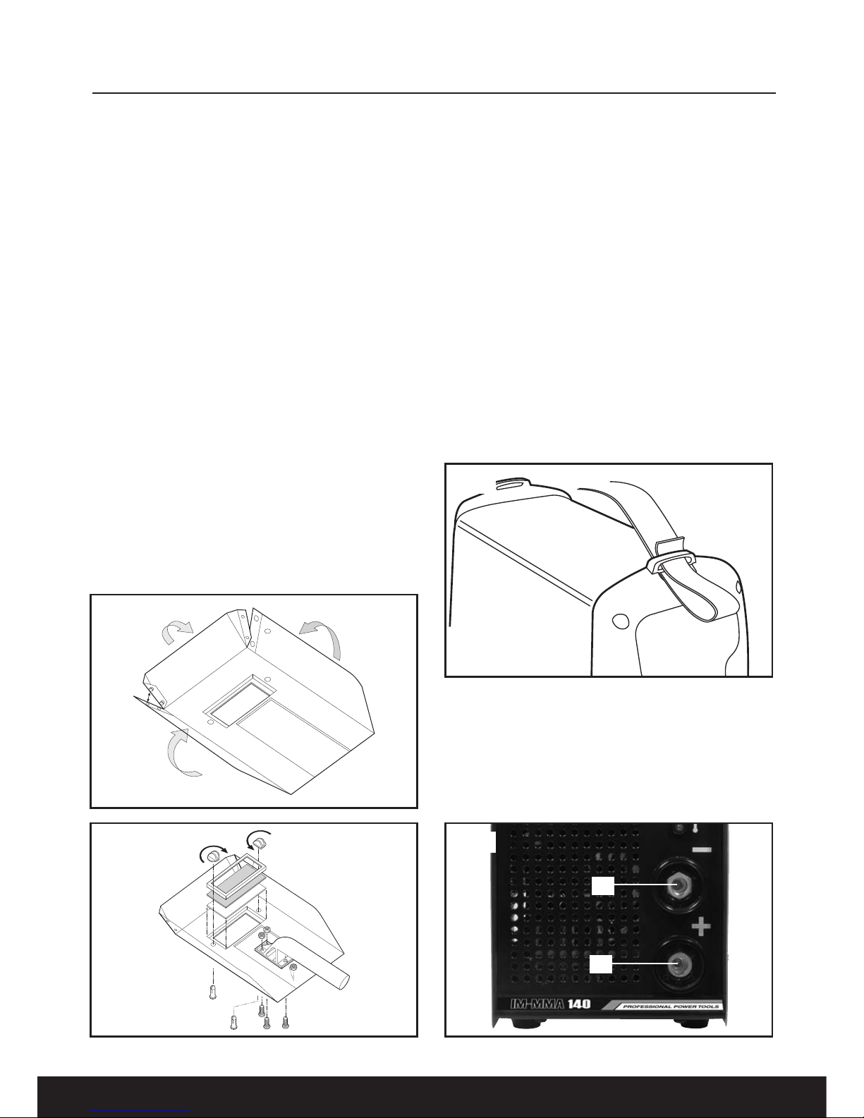
Assembling the Face Mask
To assemble the mask bend in the top and side
flaps ( ig.1) and clip into place then attach the
handle and mask glass shield as shown in ig.2.
Insert the clear glass panel first, followed by the
dark glass panel into the recess in the shield,
i.e. the clear glass MUST be on the outside of
the shield. Securing them with the plastic
screws provided.
The dark panel is a certified, specific optical
class, and should not be exchanged for any
other type.
The clear glass panel should be replaced when
it becomes badly pitted.
Warning! NEVER look at an electric arc without
eye protection as this can injure the eyes
permanently. ALWAYS use a protection mask or
welding helmet.
Fitting the Carry Handle (Fig.3)
it the carry handle as shown in ig.3 ensuring it
is fitted securely.
Fitting the Earth Clamp and Electrode Holder
Insert the plug on the end of the earth clamp
lead into the negative (-) socket ( ig.4)(A) and
twist in a clockwise direction to secure into
position. The plug on the end of the electrode
holder can be fitted into the positive (+) socket
( ig.4)(B) in the same way.
Fig 1
Fig 2
Fig 3
Fig 4
B
A
13
OPERATION
Description
Your Welding Power Supply features a single
phase transformer suitable for welding with an
alternating current using stick electrodes with
diameters from 1.6mm to 4.0mm. The welding
current is regulated by using the welding current
control (regulator).
Electrode Selection.
The pages of this manual are restricted to the
basic safe use of an MMA welding power supply
and very basic welding technique. The
electrodes used in MMA welding are many and
varied. You are advised to seek advise from your
local welding equipment supplier for the correct
selection of electrode for the work being
performed.
Operation
Warning! If you have no welding experience, we
recommend you seek training from an
experienced person.
Caution: This manual is a basic guide to
welding. We recommend you purchase a good
quality publication on welding or if you have
internet access visit one of the numerous
welding related web sites to be able to use the
welding power supply to its full potential.
THE QUALITY OF ANY WELDED JOINT IS
DEPENDANT ON THE PREPARATION OF THE
JOINT THE SELECTION OF THE CORRECT
ELECTRODE AND THE S ILL AND
EXPERIENCE OF THE WELDER.
Ensure the Welding Power Supply is
disconnected from the mains supply.
Ensure that the area of the work piece where the
earth clamp is to be connected is clean using a
file or a grinder, to ensure a good electrical
contact.
Ensure the earth lead is connected to the
workpiece, and the other lead to the electrode
holder.
Important: Ensure also that the earth clamp is
attached to clean, solid metal. If necessary
thoroughly clean with a wire brush or similar to
guarantee a good connection.
The earth clamp must only be connected to the
work piece. The area to be welded must be
clean and free from dirt, rust, paint, grease and
oil.
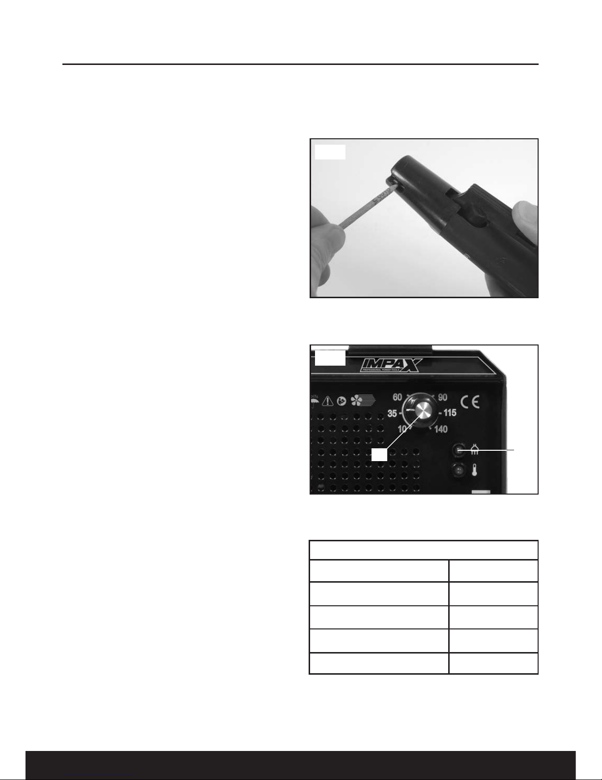
Insert an electrode into the electrode holder
( ig.5) ensuring there is a good connection.
Set the amperage (see Table 1) by adjusting the
regulator ( ig.6)(A) until the desired setting is
reached.
The chart below is an indicator of the electrode
diameter and the corresponding welding
current. This is intended as a guide only.
Fig 5
Fig 6
Table 1
Electrode diameter (mm) Amperage (A)
1.5 mm 40-55
2.0 mm 50-70
2.5 mm 75-95
3.25mm 100-140
AB

14
OPERATION
Warning! Always wear a full face mask, welding
gloves and protective clothing. Wear goggles
while chipping slag.
Do not switch on the power supply until you are
ready to start welding. Practice welding on a
piece of scrap material.
Connect to the mains supply and press the
On/Off switch ( ig.7) to the ON position (l) The
power indicator lamp on the front panel
( ig.6)(B) will illuminate. To stop the machine,
press the On/Off switch to the O position (0).
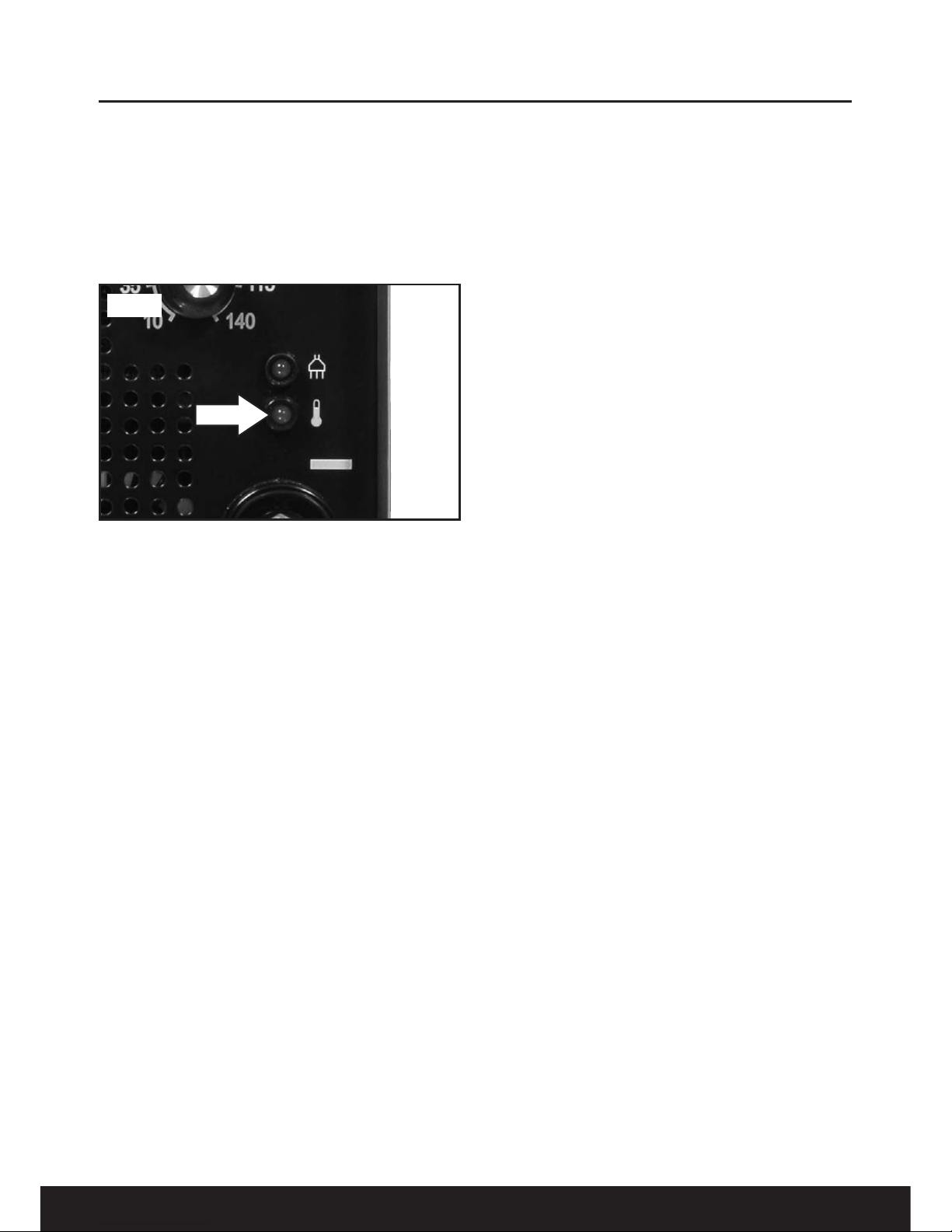
Note: If the machine stops at any time and the
amber light on the front panel illuminates, the
thermal cutout has intervened. Wait until the
transformer has cooled sufficiently for work to
recommence. This could take considerable time
and is denoted by the amber light going out.
Holding the face mask in front of your face
stroke the electrode point on the workpiece as if
striking a match. Maintain a steady gap between
the end of the electrode and the workpiece of
approximately 2mm ( ig.8).
Maintain this distance as constantly as possible
during the weld remember that the angle of the
electrode to the work piece must be 20-30°
( ig.9).
Do not hit the electrode on the workpiece as
this may damage the electrode. Withdraw with a
clean movement at the end of the welding run.
Note: This is the most difficult aspect for most
beginners. It is recommended that you practice
on some scrap material in order to get a feel of
the operation.
If the electrode is not withdrawn quickly enough
once the arc is primed, there is a possibility that
the electrode will weld itself to the workpiece.
Should this happen, give it a sharp tug to free it,
and try again. If this fails to free it, turn off the
machine immediately as it will quickly overheat.
If you withdraw the electrode too far once the
arc is primed, you will lose the arc and have to
try again.
Inspect the job carefully. With a correct
combination of electrode size and current
setting the area of weld should be complete
fusion of the electrode and parent metal/s. Any
slag which forms on the surface should be
chipped away with the pick/brush supplied.
If the resultant weld looks messy and irregular,
this is an indication of porosity or slag
contamination, and you have almost certainly
failed to achieve the correct combination. This is
a common problem, so do not worry as practice
will quickly cure this.
Fig 7
Fig 8
2mm
Fig 9
20º-30º

15
OPERATION
When welding material up to 7mm in thickness
place the pieces 2-3mm apart, run the welding
bead along the join. A second bead can go
along the underside for extra strength ( ig.10).
When welding material from 7mm to 30mm thick
prepare the material as shown in ig.11 filling up
the space with several layers of weld.
When welding together material over 30mm in
thickness prepare the material as shown in
ig.12 filling up the space with several layers of
weld, welding each side in turn with each
welding pass.
Disconnect the Welding Power Supply from the
mains supply before changing or removing
electrodes. Use pliers to remove used
electrodes from the electrode holder or to move
the welded pieces.
The Manual Metal Arc Process
When an arc is struck between the metal rod
(electrode) and the workpiece, both the rod and
workpiece surface melt to form a weld pool.
Simultaneous melting of the flux coating on the
rod will form gas and slag which protects the
weld pool from the surrounding atmosphere. The
slag will solidify and cool and must be chipped
off the weld bead once the weld run is complete
(or before the next weld pass is deposited).
The process allows only short lengths of weld to
be produced before a new electrode needs to
be inserted in the holder. Weld penetration is low
and the quality of the weld deposit is highly
dependent on the skill of the welder.
Types of Flux/Electrodes
Arc stability, depth of penetration, metal
deposition rate and positional capability are
greatly influenced by the chemical composition
of the flux coating on the electrode. Electrodes
can be divided into three main groups:
• Cellulosic
• Rutile
• Basic
Cellulosic electrodes contain a high proportion
of cellulose in the coating and are characterised
by a deeply penetrating arc and a rapid burn-off
rate giving high welding speeds. Weld deposit
can be coarse and with fluid slag, deslagging
can be difficult. These electrodes are easy to
use in any position and are noted for their use in
the stovepipe (vertical down position) welding
technique.
Features:
•• Deep penetration in all positions
• Suitability for vertical down welding
• Reasonably good mechanical properties
• High level of hydrogen generated - risk of
cracking in the heat affected zone
Fig 10
7mm
2-3mm
Fig 11
>30mm
60º
2-3mm
1
2
4
3
56
Fig 12
>30mm
60º
2-3mm

16
OPERATION
Rutile Electrodes contain a high proportion of
titanium oxide (rutile) in the coating. Titanium
oxide promotes easy arc ignition, smooth arc
operation and low spatter. These electrodes are
general purpose electrodes with good welding
properties. They can be used with AC and DC
power sources and in all positions. The
electrodes are especially suitable for welding
fillet joints in the horizontal/vertical position.
Features:
• Moderate weld metal mechanical properties
• Good bead profile produced through the
viscous slag
• Positional welding possible with a fluid slag
(containing fluoride)
• Easily removable slag
Basic electrodes contain a high proportion of
calcium carbonate (limestone) and calcium
fluoride (fluorspar) in the coating. This makes
their slag coating more fluid than rutile coatings
- this is also fast-freezing which assists welding
in the vertical and overhead position. These
electrodes are used for welding medium and
heavy section fabrications where higher weld
quality, good mechanical properties and
resistance to cracking (due to high restraint) are
required.
Features:
• Low hydrogen weld metal
• Requires high welding currents/speeds
• Poor bead profile (convex and coarse surface
profile)
• Slag removal difficult
Iron powder electrodes contain an addition of
metal powder to the flux coating to increase the
maximum permissible welding current level.
Thus, for a given electrode size, the metal
deposition rate and efficiency (percentage of the
metal deposited) are increased compared with
an electrode containing no iron powder in the
coating. The slag is normally easily removed.
Iron powder electrodes are mainly used in the
flat and horizontal/vertical positions to take
advantage of the higher deposition rates.
Efficiencies as high as 130 to 140% can be
achieved for rutile and basic electrodes without
marked deterioration of the arcing
characteristics but the arc tends to be less
forceful which reduces bead penetration.
Care of Electrodes
The quality of weld relies upon consistent
performance of the electrode. The flux coating
should not be chipped, cracked or, more
importantly, allowed to become damp.
Storage
Electrodes should always be kept in a dry and
well-ventilated store. It is good practice to stack
packets of electrodes on wooden pallets or
racks well clear of the floor. Also, all unused
electrodes which are to be returned should be
stored so they are not exposed to damp
conditions to regain moisture. Good storage
conditions are 100°C above external air
temperature. As the storage conditions are to
prevent moisture from condensing on the
electrodes, the electrode stores should be dry
rather that warm. Under these conditions and in
original packaging, electrode storage time is
practically unlimited. It should be noted that
electrodes are now available in hermetically
sealed packs which obviate the need for drying.
However, if necessary, any unused electrodes
must be redried according to manufacturer's
instructions.
Drying of Electrodes
Drying is usually carried out following the
manufacturer's recommendations and
requirements will be determined by the type of
electrode.
IMPORTANT – Thermostatic Protection
(Duty Cycle)
This product has a rated duty cycle of 40%. The
percentage represents the welding time in a 10
minute period for example 40% means that the
welding time is 4 minutes with a rest time of 6
minutes in a ten minute period although the
actual duty cycle will depend on the amperage
used. If the Welding Power Supply is used for
longer than the duty cycle or if you are welding
using large welding rods you may experience a
temporary current shut off. This is to protect the
transformer inside the Welding Power Supply
from overheating.
17
OPERATION & MAINTENANCE
The thicker the material being welded, the
greater the current required, therefore, the hotter
the machine will become and the quicker it will
cut out. When the windings reach performance
temperature the cut out switch will operate
illuminating the indicator lamp on the front panel
( ig.13). After a few minutes the cut out switch
will reset and the welder will be ready for use.
Maintenance
Warning! Ensure the welder is disconnected
from the electrical mains power supply before
attempting any service or maintenance.
The welder must be kept clean and dry at all
times. Use a dry cloth to clean the welder.
Keep the electrodes clean and dry and ensure
all cables are in good condition.
Keep the louvre passages clean to avoid a build
up of dirt and oxides inside the machine, which
can reduce machine output.
Always try to avoid getting particles of metal
inside the machine since they could cause short
circuits.
Periodically clean the inside of the welder with
compressed air, ensuring you wear a mask
during the operation.
Important - Always disconnect from the
electrical supply before servicing or cleaning.
Caution: Water must never come into contact
with the welder.
Regularly check that all the fixing screws are
tight. They may vibrate loose over time.
If the supply cord requires replacing, the task
must be carried out by the manufacturer, the
manufacturer’s agent, or an authorised service
centre to avoid a safety hazard.
Welding Mask Maintenance
Always maintain the welding mask in good
condition. If the clear glass protection lens
becomes badly pitted, sufficient to interfere with
vision, or cracked, have it replaced immediately.
NEVER use any dark filter lens other than that
provided by Impax, or one with the same
certified ‘Optical class’ (degree of protection).
The shield should always be cleaned with a
clean soft cloth after use, ensuring the lenses
are clean. Remove any dust that may have
accumulated and store it in a safe place where it
cannot be damaged.
NEVER use a shield that is not in perfect
condition.
Fig 13

TROUBLESHOOTING
18
Troubleshooting Guide
Problem Possible Cause Remedy
No weld current Blown rectifier. Replace rectifier.
(plug fuse blowing).
No weld current Poor earth clamp connection. Break in earth lead.
Break in torch lead. Check and clean up connections.
Replace earth lead. Replace torch or lead.
Unstable arc. Incorrect settings. Check settings.
Impurities in the weld area. Clean the weld area prior to welding.
Weld current interrupted. Thermal trip has operated. Allow the welder to cool down.
Porous weld. Rusty or dirty joints. Clean the weld area prior to welding.
Irregular weld cap. Torch incorrectly held. Weld with the electrode at the correct
distance and angle to the workpiece.
Poor penetration. Weld current too low. Adjust settings.
Arc too long Move the electrode closer to the
workpiece.
Excessive penetration. Weld current too high. Adjust settings.
Torch is too far from the workpiece. Weld with the electrode at the correct
distance from the workpiece.
19
EN IRONMENTAL PROTECTION & SYMBOLS
Information for (private householders) for the environmentally responsible disposal of Waste
Electrical and Electronic Equipment (WEEE)
This symbol on products and or accompanying documents indicates that used
and end of life electrical and electronic equipment should not be disposed of in
household waste. or the proper disposal, treatment, recovery and recycling,
please take these products to designated collection points, where they will be
accepted on a free of charge basis. Alternatively, in some countries you may be
able to return your products to your retailer upon the purchase of an equivalent
new product. Disposing of this product correctly will help to save valuable
resources and prevent any potential adverse effects on human health and the
environment which could otherwise arise from inappropriate waste disposal and handling. Please
contact your local authority for further details of your nearest designated collection point. Penalties
may be applicable for incorrect disposal of this waste in accordance with national legislation.
FOR BUSINESS USERS IN THE EUROPEAN UNION.
If you wish to discard electrical and electronic equipment, please contact your dealer or supplier for
further information.
Information on Disposal in other Countries outside the European Union.
This Symbol is only valid in the European Union.
If you wish to dispose of this product, please contact your local authorities or dealer and ask for the
correct method of disposal.
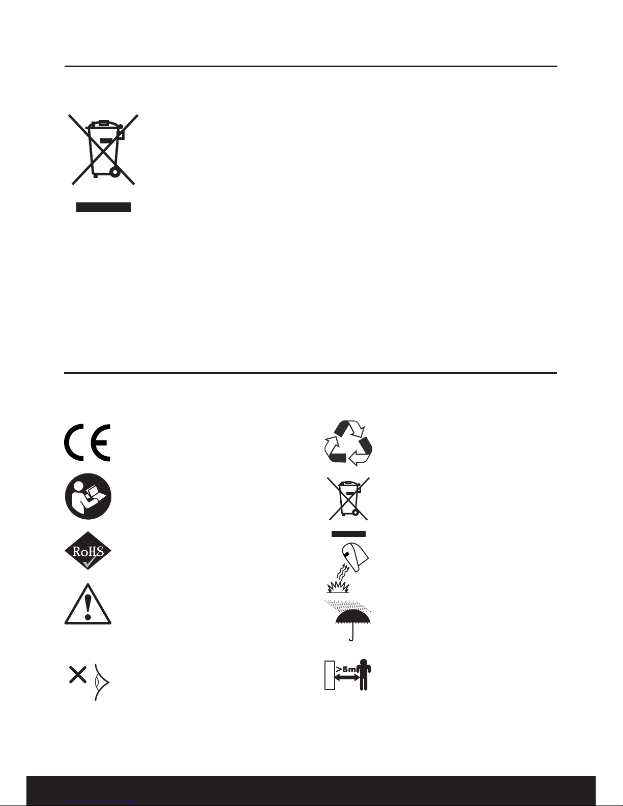
The rating plate on this product may show symbols. These represent important information about the
product or instructions on its use.
Conforms to relevant safety
standards.
Read the instruction manual.
Product conforms to RoHs
requirements
Waste electrical products
should not be disposed of
with household waste. Please
recycle where facilities exist.
Check with your Local
Authority or retailer for
recycling advice
Warning! Electrical welding
process
uV
Protect operator and passer
bye from the effect of uV
radiation. This can cause
permanant damage to the
eye. Make sure the arc and
resulting flash is shielded at
all times.
Always wear approved face
mask with correct filter,
gloves and apron to protect
against welding operation
Do not use this welder in
damp conditions
Keep bystanders and pets
clear of the welding power
supply when in use.
Table of contents
Other Impax Welding System manuals


Popular Welding System manuals by other brands

Miller
Miller Syncrowave 250 DX owner's manual

CHIEF
CHIEF MULTICUTTER MC40 operating manual

Berner
Berner PLASMACUT 54 instruction manual

Lincoln Electric
Lincoln Electric IDEALARC CV-300 Operator's manual

Clarke
Clarke EASIARC 200 Operation, maintenance & instruction manual

Migatronic
Migatronic Automation CoWelder Sigma Select 400C... Instruction handbook

Lincoln Electric
Lincoln Electric POWERFEED IM827-D Operator's manual

Miller Electric
Miller Electric SHOPMATE 300 owner's manual

FRONIUS
FRONIUS TPS/i Robotics PushPull CMT operating instructions

Servore
Servore SERVO GLAS 4000 user manual

Ilsintech
Ilsintech SWIFT F1 user manual

Magmaweld
Magmaweld ID 400E user manual


