CHIEF MULTICUTTER MC40 User manual

Operating manual
MULTICUTTER MC40
Plasma-Cutter
Item-No.: 327 958
Revision: 0.1 - Original
Version: 24.05.2013
Be sure you have read and understood this operating
manual before you carry out any works on and /
or with this
equipment!

2
© BlitzRotary GmbH
Branch Bremen
Hinterm Sielhof 22
D-28277 Bremen
Germany
Phone: +49 (0)421 / 54 90 6 - 906
Fax: +49 (0)421 / 54 90 6 - 19
E-Mail: vertrieb@elektron-bremen.de
Internet: www.elektron-bremen.de
Release:
BlitzRotary GmbH Branch Bremen

MULTICUTTER MC40
3
OPERATION MANUAL
Read this manual carefully before using the machine.
Failure to respect the rules described herein shall exempt the manufacturer from any liability.
The machine has been designed, built and protected for the functions described below. Any other
use not explicitly included shall be considered FORBIDDEN.
The machine must be used in sufficiently ventilated rooms, in the absence of dust and moisture; in
any case, where there is no risk of fire, explosion, or flooding.
The machine must be started, used and serviced by qualified personnel. Always follow current
safety regulations.
The manufacturer shall not be held responsible for any damage caused by incorrect use of the
machine.
INTRODUCTION
THIS DEVICE must be used exclusively for cutting on any electrically conductive material (metals
and alloys).
PLASMA cutting takes place due to the high temperature generated by a concentrated electric arc,
and thus highly dangerous situations may arise; it is therefore essential to pay the utmost attention
to the chapter entitled SAFETY PRECAUTIONS.
This manual must be kept carefully in a place familiar to everyone involved in using the machine. It
must be consulted whenever doubts arise and be kept for the entire life-span of the machine; it will
also be used for ordering replacement parts.
NOTE
Only use original spares.
Always replace any damaged part of the unit or torch with original material.
Do not use any torches other than the original one.
Do not let the unit work without covers. This would be dangerous for operator and for those who are
surrounding the work area and would prevent the unit from cooling efficiently.
DESCRIPTION OF TECHNICAL SPECIFICATIONS
NOTE
Should there be a claim for losses or damages it must be made by the purchaser directly to
the shipper who handled the goods.
When requesting information about this welding machine please states
number and serial number to ensure receiving accurate information relating to your machine.
The content are just for your reference.
Please be subject to the actual products if anything different or updated.

MULTICUTTER MC40
4
MODEL: The model of the machine
EN 60974-10:2003 International standards.
SN Machine Serial Number which must appear on requests or inquiries concerning the machine.
Single-phase transformer-rectifier
1-50/60Hz Single-phase input supply at 50 or 60 Hz.
Uo Secondary no-load voltage (peak value).
X Duty-Cycle Percentage
The duty-cycle is the number of minutes, expressed as a percentage, the machine can
operate (arc on) within a ten minute period without overheating. The duty cycle varies
according to the output current.
I2 Output cutting current
I1 Input Amps absorbed corresponding to different output levels (I2).
U2 Secondary voltage with cutting current I2.
U1 Nominal supply voltage
IP21 Machine case protection class. The 1 in the second digit place means that this unit is not fit
to work outdoors in the rain.
F Insulation Class
MODEL:

MULTICUTTER MC40
5
OFF
ON
DESCRIPTION OF UNIT DEVICES (see picture 1)
A) Input power cable
Confirm the input voltage before use.
B) Gas reducing unit
Adjust the gas pressure and make it is adequate to machine.
C) Control socket for torch
D) Mains switch
E) Adjustable Current knob
Adjust the current and make adequate to cut the work piece.
F) Socket for torch
G) Warning light
If something wrong with the machine, if will light.
H) Socket for work clamp
I) Gas flow delay
The time for gas flow after finish cutting.
K) Ground connector for the machine case
E G
F C H
Picture 1
I
A
K
B
D

MULTICUTTER MC40
6
SETTING AT WORK
The unit must be installed by skilled personnel. All fillings must be in conformity with the
existing rules and in full compliance with safety regulations.
Connect the air making sure that pressure is 0.3 Mpa at least .Normal 0.3-0.5 Mpa. Adjust the
pressure according to the workpiece. Recommended value is 0.4 Mpa.
Should air feed come from a pressure reducing unit of a compressor or of a centralized plant, the
reducing unit should be adjusted at the highest output pressure which should not exceed 0.8 MPa.
Should air feed come from a compressed air bottle, this should be provided with a pressure
regulator: never connect compressed air bottles directly to the reducing unit! Pressure may
exceed the reducing unit capacity and then explode!
Check that the mains power supply matches that indicated on the front panel of the machine.
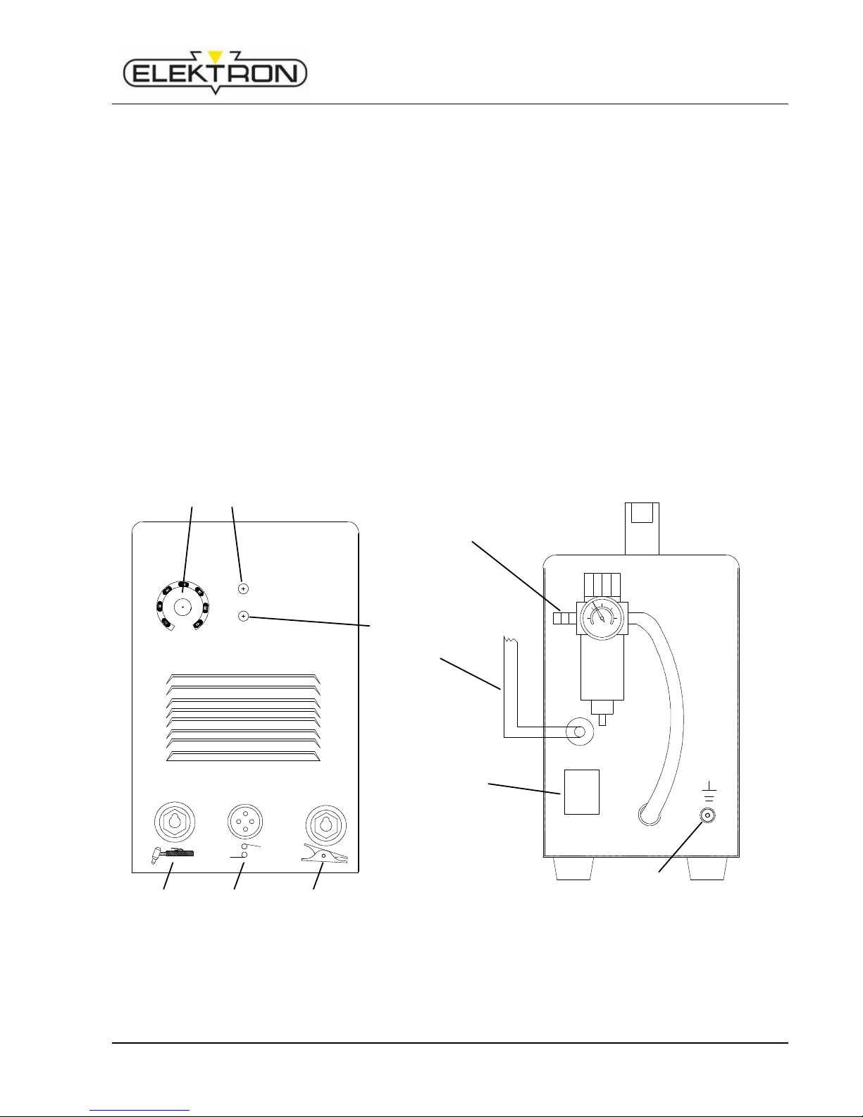
Connect supply cable A: the yellow-green wire of cable must be connected to an efficient earth plug
of the system, the remaining wires should be connected to the feed line by means of the switch
placed, if possible, close to the cutting area so as to switch the unit off quickly if necessary.
USE
Turn on the mains switch D.
By pressing for a second the torch button, the compressed air flow is opened.
Connect work clamp H to the piece to be cut.
Every machine has been disposed a power cable which must be connected to coordinated voltage class in
compliance according to input voltage of cutting machine .If cutting machine whose power voltage is 200v is
connected wrong to AC 380V ,that will cause components of inter-machine are burned up .
Make sure power cable A is connected to power switch reliably and prevent from oxidizing.
Make sure power voltage is inside the waved range.
Welding circuit should not be deliberately placed in direct or indirect contact with protection wire if
not in the workpiece. If earthing is deliberately made on the workpiece by means of protection wire,
the connection must be as direct as possible, with the wire having a section at least equal to the
welding return current wire and connected to the piece being worked on, in the same place as the
return wire, using the return wire terminal or a second earth terminal closeby.
All possible precautions must be taken in order to avoid stray currents.
Clean the work piece to ensure good electrical contact of the work clamp.
Do not connect work clamp to the material to be removed.
Press torch button to start pilot arc, if cutting does not start after 2 or 3 seconds, the pilot arc turns
off and the button should be pressed again to repeat the operation.
When possible, the torch should be pulled. Pulling is easier than pushing.
Keep torch in vertical position when cutting.
Once cutting is over and after releasing button, air continues to flow out of the torch for about 40
seconds so it enables torch to cool down. It is recommended not to turn the unit off before that time.
Should holes be drilled or should the piece be cut starting from its center, torch should be tilted and
then slowly straighten to prevent molten metal from being spread on nozzle (see picture 4). This
operation should be carried out whith material thickness above 2 mm. If you have to cut near angles
or recesses (see picture 5) it is recommended to use extended electrodes and nozzles.
N.B. : Avoid keeping pilot arc uselessly on, in air to avoid electrode, and nozzle
consumption.
When you have finished working, turn off the machine and hang the torch on the
hook provided.

MULTICUTTER MC40
7
CUTTING TROUBLE
1) Insufficient penetration
This may be due to:
high speed. Always make sure that arc thoroughly passes through the piece to be cut and that it is
not tilted, when going forward, by a percentage above 10 / 15°(see picture 6). It is thus avoided to
wear nozzle (see picture 7) out and to burn the nozzle holder (see picture 8).
Excessive thickness of piece (see graph of cutting speed and thickness)
Work clamp H not properly in electric contact with piece
Worn nozzle and electrode
Too low cutting current.
N .B. : When the unit does not thoroughly pass through, nozzle is clogged by scums.
2) Cutting arc switches off
This may be due to:
worn nozzle, electrode or diffuser B
too high air pressure
too low feed voltage
3) Tilted cutting
When cutting is tilted (see picture 9) switch the unit off,
loosen nozzle holder and turn nozzle by a quarter turn, then
lock and try again.
Repeat until cutting is straight (see picture 10).
4) Excessive wear of consumable parts
This may be due to:
a) too low air pressure with respect to the recommended one
b) excessive bums on the end part of nozzle holder.
PRACTICAL RECOMMENDATIONS
If the system air contains much humidity and oil it is required to use a drying filter to avoid excessive
oxidation and wear of consumable parts, to avoid torch damage or to reduce speed and quality of
cutting.
Impurities of air favour oxidation of electrode and nozzle and make it difficult to start pilot arc. If this
occurs, clean the end part of electrode and inside the nozzle with fine abrasive paper.
Make sure that new electrode and nozzle to fit are clean and degreased.
To avoid damage of torch and to prevent dangerous situations always use genuine spares.
TORCH MAINTENANCE
The introduction for torch are just for your reference.
Please be subject to the actual products if anything different or updated
Replace wear parts (picture 11)
The parts subject to wear are electrode A, diffuser B and nozzle C. nozzle holder D.
Either part may be only replaced after loosening nozzle holder D. Electrode A should be replaced
when a 1.5mm deep crater is created in the middle (see picture 12).
ATTENTION! Do not make sudden stresses when unscrewing the electrode, but gradually
force so as to have the thread unlocked. Lubricate the thread of the new electrode with
silicone lubricant (on supply with the unit). This new electrode is required to be screwed in
its housing and locked without tightening.

MULTICUTTER MC40
8
Nozzle C should be replaced when its central hole is damaged or enlarged with respect to the new
part (see picture 13).
Use of worn electrode quickly wears out the nozzle.
Excessive use of electrode causes overheating and reduces the life of diffuser B.
Make sure that after replacing it, nozzle D is tight enough.
ATTENTION! Nozzle holder D should be only screwed on head when electrode A diffuser B
and nozzle C are assembled.
safety.
MAINTENANCE AND CONTROL
It is recommended to keep nozzle free from slag.
Avoid using sharpened bodies thus avoiding damaging the nozzle hole.
Even if the unit is provided with an automatic device for water discharge, working whenever air feed
is closed, it is recommended to check from time to time that no water remains in trap I of reducer
(picture 1).
It is required to clean from time to time the unit inside and make it free from metal dust by means of
compressed air.
Operations to be carried out inside the unit must be effected after disconnecting feed cable.
BASIC SAFETY PRECAUTIONS
ELECTRIC SHOCK
Electric shock can kill. All electric shocks are potentially fatal.
This plasma cutter requires high voltages for arc spark starting (approx. 250 / 350 V). The following
safety rules must be therefore observed when using the unit:
Do not touch live parts.
Insulate yourselves from the piece to be cut and from earth by wearing insulating gloves and
clothing
Keep your clothing (gloves, shoes, hats, dresses) and body dry
Do not work in humid or wet areas.
Avoid touching or holding by hand the piece to be cut.
Always arrange for a proper insulation against electric shock.
Should you work close to or in a dangerous area use all possible precautions.
If you feel even the slightest electric shock sensation, stop cutting at once. Do not use the machine
until the problem is identified and solved.
Always fit an automatic wall switch with adequate power. if possible close to the machine so as to
immediately switch the unit off in an emergency event.
Check often mains cable, torch cable, earth cable and torch.
Never use the unit when one of them is damaged. Replace them immediately.
Disconnect mains cable from mains before replacing cables or before removing unit covers.
Always switch the unit off or disconnect it before replacing nozzle, swirl ring, electrode or nozzle
holder.
Do not use the unit without protecting covers.
Always replace any damaged parts of the unit, torch and cables with original material.
Never remove torch or unit safety devices.

MULTICUTTER MC40
9
Make sure that the supply mains line is equipped with an efficient earth plug.
Make sure that the work table is connected to an efficient earth plug.
Maintenance should be only carried out by qualified personnel aware of the risks due to dangerous
voltages necessary to make the unit work.
RADIATIONS
Ultraviolet radiations created by the arc may damage your eyes and burn your skin. Then:
Wear proper clothing and helmets.
Do not use contact lenses! The intense heat coming from
the arc may stick them on the cornea.
Use masks with grade DIN 10 safety lenses, at least.
Protect people surrounding the cuffing area.
FUMES
Cutting operations give off fumes and harmful metal dusts which may damage health,
therefore:
Do not work in areas without proper ventilation.
Keep your head out of fumes.
In closed rooms use suitable exhaust fans, placed under the cutting area, if possible.
It ventilation is not enough, use breathing sets approved for this procedure.
Clean the material to be cut of any solvents or halogen degreasers giving rise to toxic gases when
cutting: Some chlorine solvents may decompose with radiation emitted by the arc and create
phosgene gas.
Do not cut plated metals or metals containing lead, graphite, cadmium, zinc, chrome, quicksilver or
beryllium unless you have a proper breathing set.
The electric arc creates ozone. After long exposure to high concentrations of ozone you may have
headache, nose, throat and eyes irritation as well as serious congestion and chest pains.
IMPORTANT: DO NOT USE OXYGEN FOR VENTILATION.
FIRE
Avoid causing fire because of sparks, hot metal or pieces.
Make sure that suitable fireproof devices are available close to cutting area.
Remove from cutting area and surrounding area (33 feet at least) all inflammable and combustible
material.
Do not cut containers of combustible or lubricating material, even when empty. These should be
carefully cleaned before being cut.
Let the material cut cool down before touching it or putting it in contact with combustible or
inflammable material.
Do not cut parts with hollow spaces including inflammable material.
Do not work under conditions of high concentration of combustible vapours, gases or inflammable
dust.
Always check the work area half an hour after cutting so as to make sure that no fire is starting to
burn.

MULTICUTTER MC40
10
BURNS
Wear fire-proof clothes all over your body to protect your skin against burns caused by ultraviolet
radiations from the arc, from sparks and hot metal.
Wear no turn-up trousers to prevent sparks and metal to deposit in them.
Wait for the torch to be cooled down and then switch the unit off before touching the front side of the
torch.
Torch is provided with a pilot arc, then as soon as you press the button, the plasma spark
starts even if earth cable is not connected. Avoid directing jet towards your own body or
towards other people surrounding the cutting area.
To prevent spark to starts by chance, always switch the unit off before putting down your
torch.
Do not carry combustible material, such as lighters or matches in pocket.
EXPLOSIONS
Do not cut above or near containers under pressure.
Do not cut in environments containing explosive 4 dusts, gases or vapours.
This plasma cutter uses compressed air to work; should you use compressed air bottles follow
suitable precautions:
A) CYLINDERS
Do not directly connect cylinders to reducing unit without a pressure regulator; pressure might
exceed the reducing unit capacity making it explode.
Feeding pressure must not exceed 0.8MPa
Handle or use pressure cylinders in conformity with the existing rules.
Do not use leaking or damaged cylinders.
Do not use cylinders which are not properly secured.
Do not carry cylinders whose content is not clearly identified.
Never lubricate cylinder valves with oil or grease.
Do not put electrically in contact cylinder with plasma arc.
Do not expose cylinders to excessive heat, sparks, hot metal or flames.
Do not tamper with cylinder valves.
Do not try to losen all tight valves by means of hammers, keys or something else.
B) PRESSURE REGULATORS
Keep pressure regulators in good conditions. Damaged regulators may give rise to damage or
accidents; they should only be repaired by skilled personnel.
Do not use regulators for gases other than those they are manufactured for.
Never use a leaking or damaged regulator.
Never lubricate regulators with oil or grease.
C) AIR HOSES
Replace air hoses if damaged.
Keep hoses unwound so as to avoid bending.
Keep excess hose wound and keep it out of the working area to avoid any damage.
NOISE
These power sources alone do not produce noise levels exceeding 80 dB. The cutting
procedure, however, may produce noise levels in excess of 80 dB in which case the operator must
take the necessary safety precautions as prescribed by the national safety regulations.

MULTICUTTER MC40
11
PACEMAKER
Magnetic fields created by the high currents in the cuffing circuit can affect pacemaker operation.
Persons wearing electronic life support equipment (pacemakers) should consult their doctor before
going near any arc welding, gouging, cutting, or spot welding equipment in operation.
picture 4-13
B A C D
picture 14 (torch)

MULTICUTTER MC40
12
ILLUSTRATION OF WORKING PRINCIPLE
MULTICUTTER MC40

MULTICUTTER MC40
13
ILLUSTRATION EXPLODED MULTICUTTER MC40
No
Description No
Description
1
potentiometer 2W 14
gas connector
2
red LED 15
fan
3
power switch 3
fan cover
4
T300 switch 16
Radiator (right)
5
CK-25 quick socket (with gas)
17
MULTICUTTER PCB (up)
6
DKJ1-10-25MM quick socket 18
handle
7
control socket (machine side)
19
Radiator (left)
8
MULTICUTTER Pilot arc PCB
20
pilot arc resistance
9
foot 21
outside cause
10
MULTICUTTR PCB (down) 22
MULTICUTTER PCB (mid)
11
rectifier 23
bottom board
12
solenoid valve 24
front panel
13
power cord 25
plastic frame

B li tz Ro t ar y Gm b H B ra n ch B re me n Hi n te r m S ie lh of 2 2 D - 282 7 7 B re me n
Telephone +49 / (0)421 / 54 90 6-906 Telefax +49 / (0)421 / 54 90 6-19 vertrieb@elektron-bremen.de www.elektron-bremen.de
Table of contents
Other CHIEF Welding System manuals

CHIEF
CHIEF M30 User manual

CHIEF
CHIEF MIG 240 208/240 V User manual

CHIEF
CHIEF Elektron MultiMig 621 User manual

CHIEF
CHIEF MultiMig 721 Multivoltage User manual

CHIEF
CHIEF MI200T User manual

CHIEF
CHIEF M30 Pro ALU User manual

CHIEF
CHIEF Electron MultiSpot M25 AL User manual

CHIEF
CHIEF Multi-Spot M22AL User manual

CHIEF
CHIEF MultiMig 511 User manual

CHIEF
CHIEF MultiMig 521 User manual
Popular Welding System manuals by other brands

ESAB
ESAB Precision Plasmarc EPP-600 instruction manual

Daihen
Daihen OTC Welbee M350L owner's manual

Meec tools
Meec tools 016793 operating instructions

Leister
Leister AIRSTREAM 100 instruction manual

Lincoln Electric
Lincoln Electric WELDANPOWER 230+ operating manual

Raptor
Raptor RAPPACT3110 installation instructions