impey Aqua-Grade Linear User manual

Aqua-Grade Linear
Installation Guide
Issue 2
01/12/15
CONTENTS
Please read and understand this installation guide fully before attempting to install the product.
Always allow new screeds to fully dry before applying the final finish of waterproofing and tiles.
Further guidance can be found in BS 8204 or BS 5385-3:2007
Please follow all installation guides supplied with the Linear drain and waterproofing systems.
Section 1, Components
Section 2, Configuration types
Section 3, Basic assembly rules
Section 4, General Installation guidance
Section 5, Assembly methods
If you require any further information about this product please contact our technical team on: 01460 258 682
SAFETY
•
Please read these installation instructions carefully before proceeding.
•
Keep guide for future reference.
•
Incorrect installation will invalidate the guarantee.
•
Make sure there are no hidden pipes or cables in the floor or walls where you intend to drill.
•
Wear safety goggles, shoes and appropriate clothing.
•
Impey Showers, Conquest Business Park, Ilton, Somerset, TA19 9EA, TEL: 01460 256090 FAX: 01460 259800
[email protected] www.impeyshowers.com
Page 2
Page 3
Page 4
Pages 5-7
Pages 8-12

SCR/CNR30/BU
Corner section
SCR/INF30/GN
300mm section
SCR/INF45/RE
450mm section
SCR/INF15L/GN
150mm section
Left hand
SCR/INF15R/GN
150mm section
Right hand
SCR05
M8 Foot
SCR06
Spacer M8 foot only)
SCR/FMP
Foot mounting plate
SCR/SPACER
Spacer for moulded foot
SCR/FOOT
Moulded foot
SCR/IMP Insulation mounting plate
Optional (available separately)
Can be used with both types of foot.
Section 1: Components
Page 2
Parts used with starter section only
Main assembly parts
AGLNR40, starter section for 400mm Linear drain
AGLNR60, for 600mm drain
AGLNR80, for 800mm drain
(Section supplied will be dependant on configuration and size of Aqua-grade Linear)

0 Walls required, 4 falls of gradient
1 Wall required, 3 falls of gradient
2 Walls required, 2 falls of gradient
3 Walls required, 1 fall of gradient
Section 2: Configuration types
The Aqua-grade Linear may be arranged in a wide range of sizes and configurations,
use this section to familiarise yourself with the 4 main types.
Page 3

Always work in a clockwise or right to left direction
when assembling.
Without support
section will collapse
No previous section,
no support
Additional foot
Supported by
previous section
5
150
2°
21mm - 30mm
42
72
47
52
57
62
67
A
B
C
Sub floor
Wall
Row 1 Row 2 Row 3 Row 4 Row 5 Row 6
Diagram 5.
A
B
C
Section 3: General Installation guidance
for all configuration types
This section is an introduction to the basic installation and assembly rules for Aqua-grade Linear.
It is important that you have read and understand these requirements before commencing installation.
Page 4
The blue corner section must always have 2 feet fitted.
When using configurations that start from a wall it is
important that 2 feet are fitted to the first section to
support the section properly.
(excludes SCR15L and SCR15R parts)
All parts have gradient slope built in,
you do not need to
adjust the feet to add gradient only to adjust height.
Using these dimension it is possible to calculate the
overall approximate finished depth required to install.
As more rows are added the adjustable feet will need to have spacers added to ensure correct gradient and levels are
maintained. The general rule is to add 1 spacer to each foot for every 2 rows that are added. (see above).
Extra spacers are supplied to help with subfloors that are very uneven or not level.
SUBFLOOR
SUBFLOOR
WALL
WALL

1
Determine where the Aqua-grade linear will be installed.
(if the product is being installed into an existing floor the
screed will need to be excavated first.)
2
Measure out and mark the position of the waste pipe
and gully.
3
Using appropriate tools, excavate enough concrete
to allow the waste to be fitted.
5
Take the yellow starter section and screw in the
levelling feet. Then clip the feet mounting plates onto
levelling feet.
4
Install the gully and waste pipe in an approved manner.
6
Position the starter section correctly and mark the
position of the mounting plates. Temporarily place the
drain channel into the starter section and connect the
waste to ensure correct positioning.
Section 4: General Installation guidance
for all configuration types
This section covers parts of the installation that are are common to all configuration types.
Please see section 5 and follow the relevant stages that are applicable to the type you are installing.
Page 5

7
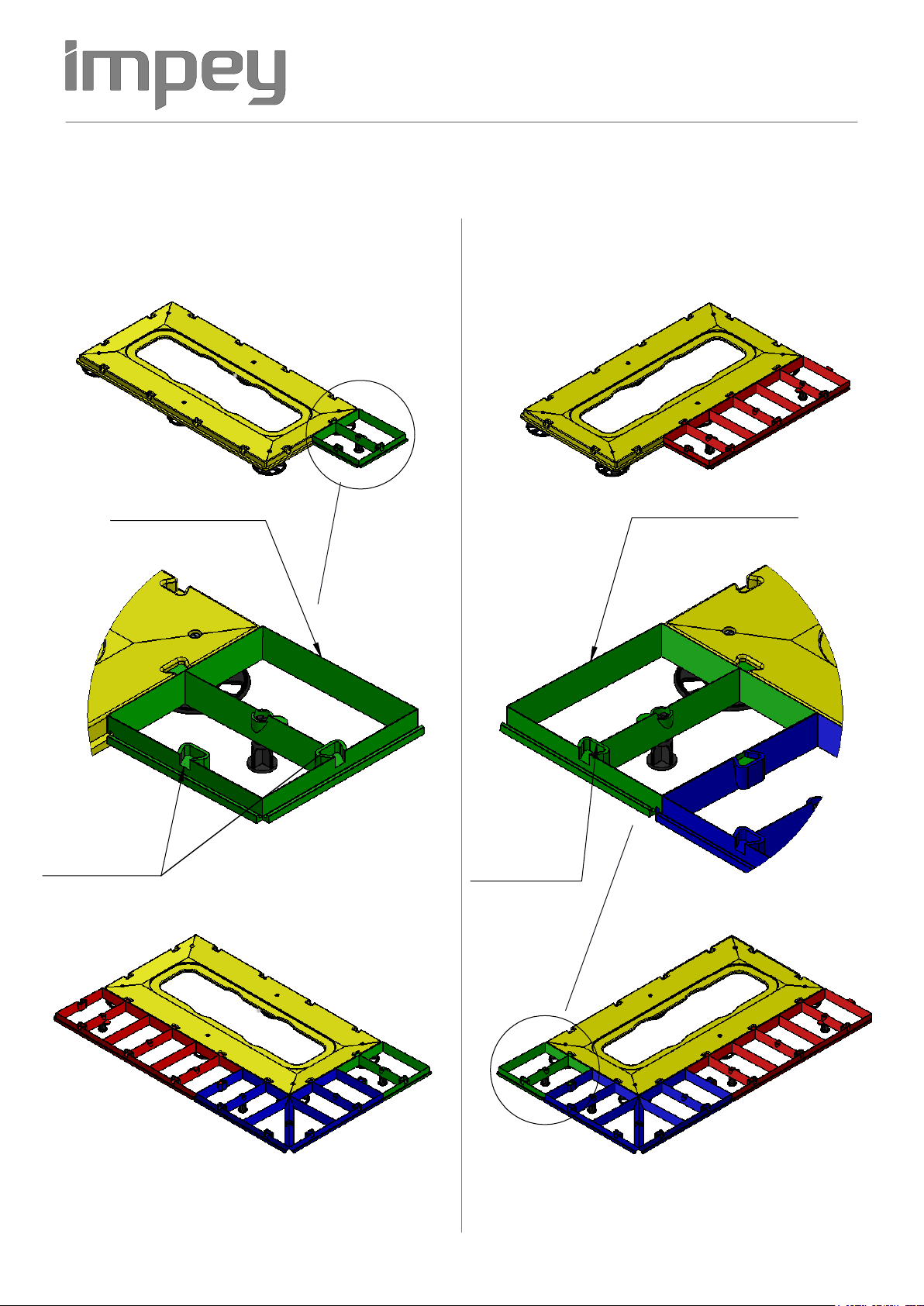
Remove the mounting plates from the feet, drill and
fix them to the sub floor to secure them in position.
9
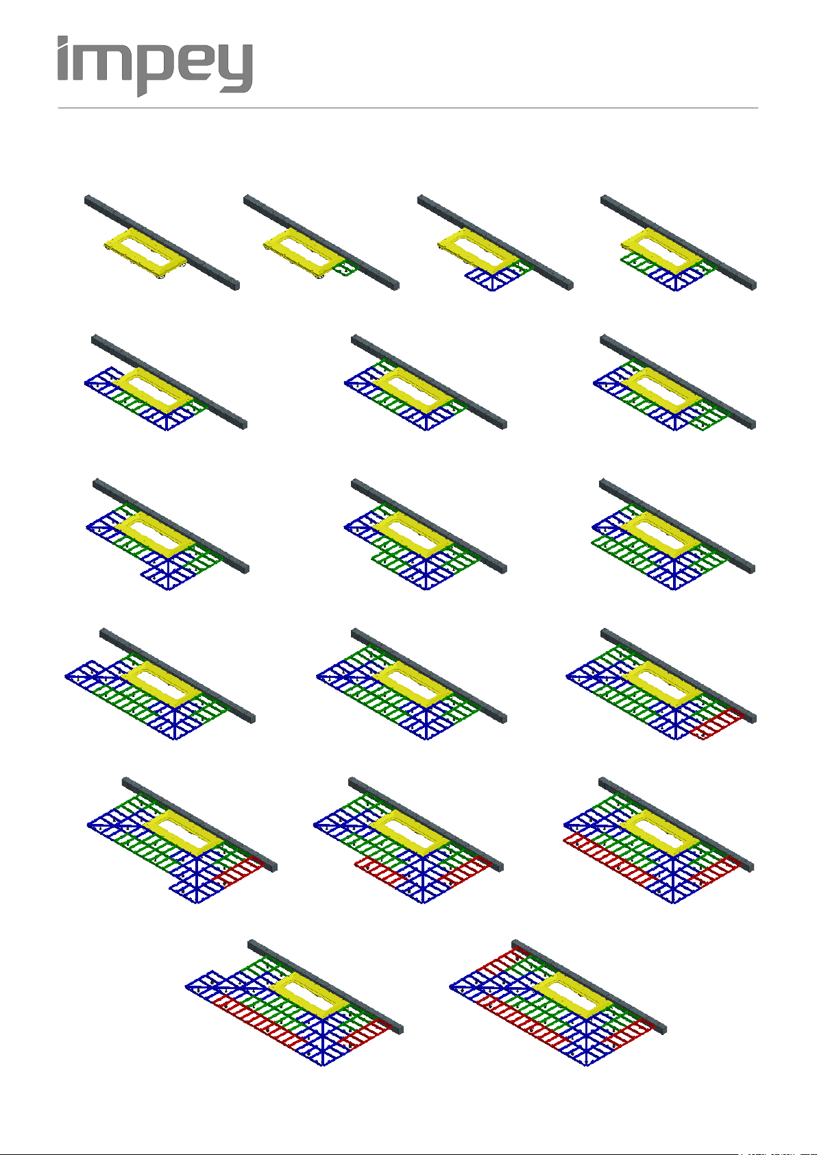
Using a screwdriver and spirit level adjust the levelling
feet until all outside edges are level.
Ensure the height is set correctly at this stage also.
(see diagram 5 on page 4 for further guidance)
10
At this stage we recommend that the waste pipe is buried
and the the starter section is bedded. This can be done by
pushing sand/cement under the section. It may be preferred
to temporarily remove the linear channel to do this.
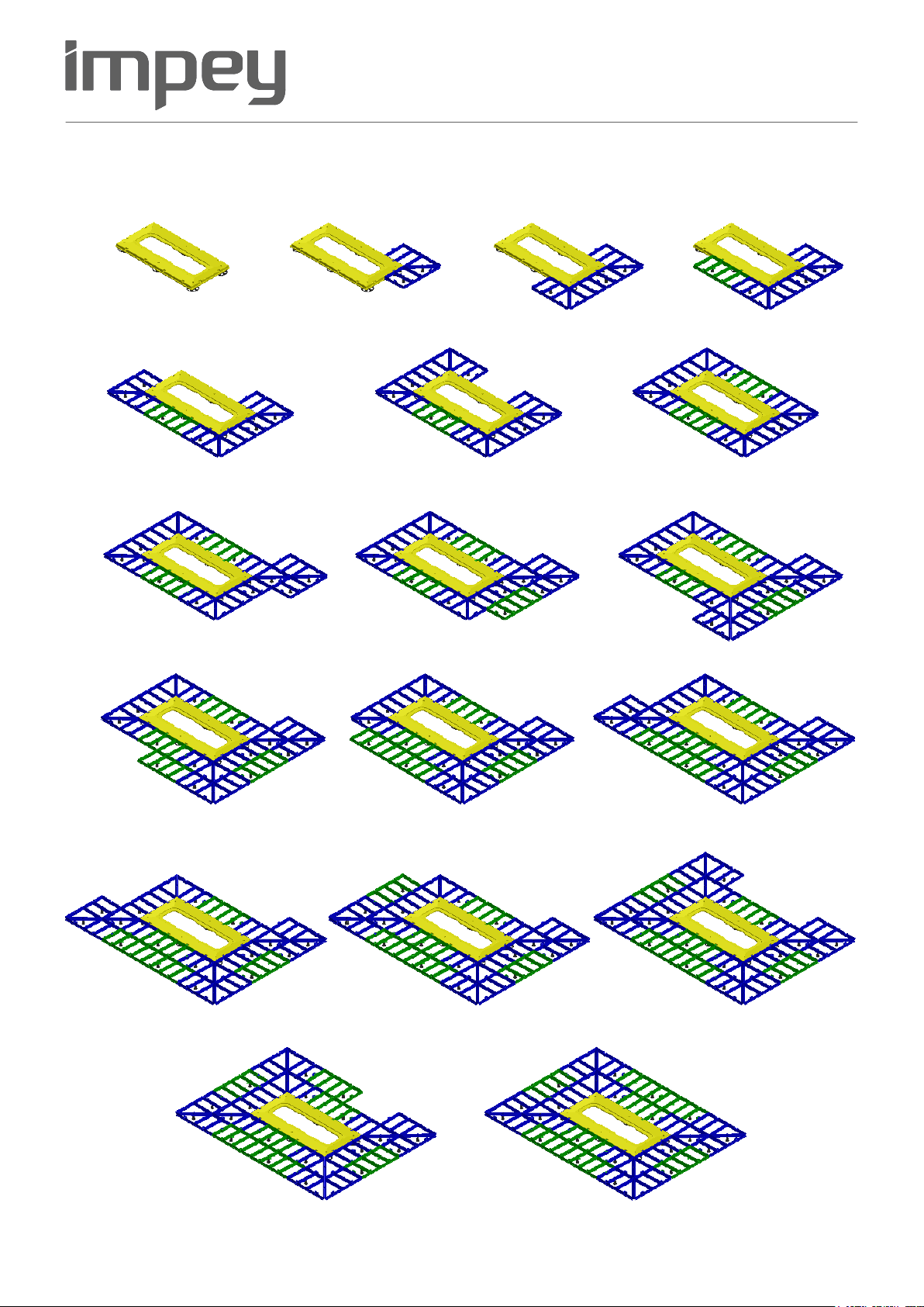
11
Begin adding the first section, ensure it is fully located
and levelled correctly. (this illustration shows a corner
section but this is dependant on the configuration type)
12
When making levelling adjustments it is important that
the feet are only just in contact with the sub floor, being
careful not to over or under adjust.
8
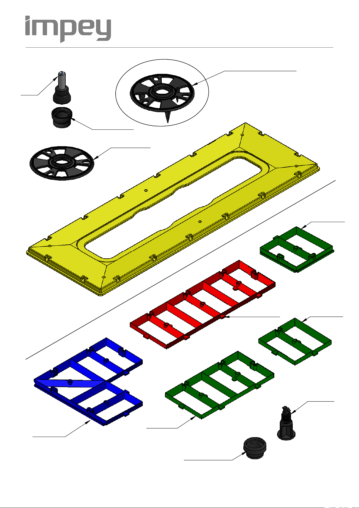
Reposition the starter section and clip into the mounting
plates. Place the Linear channel into the starter section,
drill and fix in place. (also see drain assembly guide)
Ensure screw is fitted to
connect gully to Linear channel.
(do not over tighten)
Section 4: General Installation guidance
for all configuration types
This section covers parts of the installation that are are common to all configuration types.
Please see section 5 and follow the relevant stages that are applicable to the type you are installing.
Page 6

14
Working in a clockwise direction continue to add parts.
After completion of each row the outer edges must be
level.
15
Continue adding parts and levelling in the same manner.
16
When the assembly is complete we recommend that the
outer perimeter is shuttered to prevent screed escaping
whist backfilling is carried out.
17
Begin filling the Aqua-grade with a semi dry screed mix and
smooth off with a wooden or plastic float.
Ensure the screed is compacted well to prevent hollow areas.
18
When fully filled it may be necessary to allow the screed
to dry out slightly before final finish trowelling.
When complete the shuttering can be removed and the
remaining floor finished.
13
When the first section has been adjusted continue adding
the remaining components for the configuration you are
installing. Follow the relevant assembly diagrams in section 5.
Section 4, General Installation guidance
for all configuration types
This section covers parts of the installation that are are common to all configuration types.
Please see section 5 and follow the relevant stages that are applicable to the type you are installing.
Page 7

1. 2. 3. 4.
6. 7.
9.
10.
11. 12.
15.
13.
16.
14.
18.
17.
Section 5, Assembly order for 4 falls,
no walls configuration
5.
Please follow these steps as a general guide for this type of configuration, (alternative sizes are available)
Always work in a clockwise or right to left direction.
After each row is completed ensure the outside edge is level.
8.
Page 8

2. 3.
4. 5. 6.
7. 8. 9.
10. 11. 12.
13. 14. 15.
17.
4.
Section 5, Assembly order for 3 falls,
1 wall configuration
Please follow these steps as a general guide for this type of configuration, (alternative sizes are available)
Always work in a clockwise or right to left direction.
After each row is completed ensure the outside edge is level.
1.
16.
Page 9

A
Left hand section
2 x Open joints
B
1 x Open joint
Right hand section
Section 5, Additional information
for 2 walls, 2 falls configuration
The configuration with 2 falls 2 walls (corner drain) can be assembled as Left hand and Right hand version.
The assembly process for these is slightly different, please see notes below and assembly guide for these types on page 11
Parts for both versions are supplied in the pack, these parts are very similar, please see notes to assist with identification
Left Hand Configuration
Right Hand Configuration
Page 10

Left Hand Version
1. 2. 3.
4. 5. 6.
8.
7.
12.
9.
10. 11.
1. 2. 3.
4. 5. 6.
7. 8.
Section 5, Assembly order for 2 falls,
2 walls configuration (left and right hand)
Please follow these steps as a general guide for this type of configuration, (alternative sizes are available)
Always work in a clockwise or right to left direction.
After each row is completed ensure the outside edge is level.
Right Hand Version
Page 11

1. 2. 3.
4. 5. 6.
7. 8. 9.
10. 11.
Section 5, Assembly order for 1 fall,
3 walls configuration
Please follow these steps as a general guide for this type of configuration,
Always work in a clockwise or right to left direction.
After each row is completed ensure the outside edge is level.
Page 12