manuals.online logo
Brands
  1. Home
  2. •
  3. Brands
  4. •
  5. SAFERA
  6. •
  7. Household Appliance
  8. •
  9. SAFERA Smart R Stove Guard User manual

SAFERA Smart R Stove Guard User manual

1
5
INSTALLATION MANUAL
V4.2.1 ENG SMART R PCU3
SAFERA Smart R Stove Guard
with power control unit PCU3
2
CONTENTS
1. Preparations
2. Installation
3. Troubleshooting
4. Optional: Installing the Water Leakage
Sensor
Follow these instructions carefully and
pay particular attention to the instruc-
tions marked in the following way:
WARNINGS
ѥWARNING
Follow instructions marked with a warn-
ing accurately to prevent injury to per-
sons and damage to property.
ѥWARNING
Read user and installation manual before
using or installing the appliance.
Install and check the application accord-
ing to the instructions. SAFERA is not li-
able for any damages or expenses caused
by inappropriate installation.
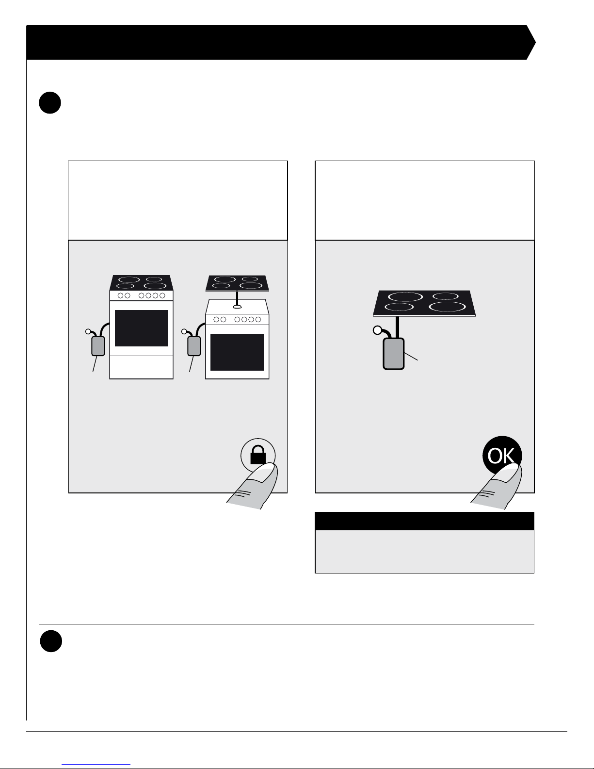
Check that the Stove Guard is compatible
with the cooker (see section 1.1).
If the network cable is damaged, it must
be replaced by the service personnel of
the manufacturer or their representative
to avoid hazards.
All electrical connections must be carried
out by a qualied electrician.
⚐ATTENTION
Follow instructions marked with a note
carefully to prevent damage to property.
⚐ATTENTION
If the appliance was stored in a cold
space, it must be allowed to warm up to
room temperature before connecting it to
electric network.
ѧHINT
Hints give you useful advices on using the
appliance.
3
1. PREPARATIONS
Check the product and the contents of the
package before installation:
• Central Unit Ⓐ
• Power Supply Ⓓ
• Power Contro l Unit Ⓒ
• User and installation manual
• Declaration of Conformity
ѥWARNING
Please contact your vendor if you notice
anything unusual about the appliance.
1.1 Compatibility
SAFERA cooker guard is compatible with
most electrical cookers, hobs and ovens
meant for household use:
• Traditional cast-iron cookers and hobs
• Ceramic cookers and hobs
• Induction cookers and hobs
• Cookers and hobs equipped with a
timer, afterheat indicator, child proof
lock or integrated switch-off system
SAFERA Smart R is compatible with cook-
ers no wider than 90 cm, see installation
step 1/6.
1.2 Control Panel
❶ Child proof lock button
❷ OK button
❸ Indicator light for child proof lock
❹ Indicator light for normal activity
❺ Warning light for cooktop hazard
❻ Warninglightforcooktopre
(optional)
❼ Warning light for water leakage
❽ Adjustment mode button
❾ Indicator light for service need
❾
❷❶❸❾❽ ❹ ❻❺ ❼
C
A B
D
4
Install the Central Unit Ⓐaccording to the dimensions below.
Width
Align the Central Unit
±15 mm with the cen-
tre of the cooktop.
Depth
Align the sensor of Cen-
tral Unit (white lens)
±100 mm with the cen-
tre of the cooktop.
497 or 597 mm
Cooker
width
Installation
Height
Max. 60 cm 45 - 75 cm
60 - 90 cm 60 - 75 cm
INSTALLATION - STEP 1/6 Mount the Central Unit Ⓐ.
5
Mount the Central Unit Ⓐ. You have two mounting options:
5
1
4
56
1
2
2
3
3
A
B
10mm
⚐ATTENTION
The Central Unit Ⓐis plugged into the
wall socket with its own power supply Ⓓ.
6
INSTALLATION - STEP 2/6 Mount the Power Control Unit Ⓒ.
OUTIN
PE
L/N
L
PE
N
L
L
230V 16A
400V 10A
230V 16A
400V 10A
230V 16A
400V 10A
MAX
MAX
MAX
L1
L2
L3
MICRO DISCONNECTION
ѥWARNING
Make sure that there is no power supply
to the cooker and the oven by removing
their fuses. Also ensure that the cooker is
switched off.
OUT-wires are always energized when the
power control unit is connected to the elec-
trical network. If a wire is loose, it must be
properly covered.
If the element voltage of the cooker is 400
V, the fuse can only be maximum of 10 A.
If the element is 230 V, the fuse can only be
maximum of 16 A.
Do not install the Power Control Unit to
excessive heat: Operational ambient tem-
perature is +5 … +40°C.
⚐ATTENTION
Power Control Unit requires a neutral
wire to operate.
Install the power control unit Ⓒ so that it
is not exposed to moisture. Check that all
cables can move freely.
Install the Power Control Unit PCU3.
ѧHINT
If you are replacing a cooker, press the
adjustment mode button ❼ for ve sec-
onds until you hear a signal. Continue the
installation according to step 3/6.
OFF
7
IN
5 x 2,5 mm2
0,7 m
OUT
5 x 2,5 mm2
1,3 m
180 mm
60 mm
130 mm
Optional water sen-
sor connection.
See chapter 4.
Mount the Power Control Unit on the wall behind the cooker or into the cabinet
next to the cooker.
Coupletheprotectiveearthrst(PE).
Couple the other wires.
Don’t reconnect the power to the cooker yet.
Installation
3
4
2
1
8
C
A B
D
C
A B
D
Connect the power supply
Ⓓ to the Central Unit Ⓐ.
Put back the fuses for the
cooker and the oven. The
Power Control Unit Ⓒ will now
contact the Central Unit Ⓐ
whichgivesasoundsignal(•••).
3
Press the adjustment
mode button ❽: indicator
lights ❺, ❻ and ❼start blinking
by turns.
2
ѧHINT
You can re-start the installation process
anytime by pressing the adjustment mode
button ❽ for ve seconds until you hear
the signal.
1
INSTALLATION - STEP 3/6 Set up the wireless connection
ON
9
When the indicator lights for child proof lock and normal activity (❸ and ❹) start
blinking by turns, calibrate the cooker. Choose from the two options:
Kalibroi virranhallintayksikkö
1
INSTALLATION - STEP 4/6 Calibrate the system
Check that the indicator light for normal activity ❹blinkseveryveseconds.
2
ѧHINT
With induction cooker, use a compat-
ible dish.
OpTION 2:
Only cooktop is connected to
the Power Control Unit Ⓒ.
Turn on the biggest cooker plate
with maximum power and press
the OK-button ❷. When
you hear a sound signal
(•••),turnoffthecooker.
Ⓒ
OpTION 1:
Cooker and oven are connected to
the Power Control Unit Ⓒ.
Turn on the oven and press the
child proof lock button ❶. When
you hear a sound signal
(•••),turnofftheoven.
ⒸⒸ
or
or
10
INSTALLATION - STEP 5/6 Adjust the alarm limit
Location of the
Cooker
Installation
Height
Alarm Limit
(1-12)
In a corner 75 cm 6*
65 cm 7
55 cm 8
45 cm 9
Next to a wall 75 cm 5
65 cm 6*
55 cm 7
45 cm 8
In an island 75 cm 4
65 cm 5
55 cm 6*
45 cm 7
Adjust the alarm limit according to the reference table above.
The default alarm limit is 6.
First, go to the adjustment mode:
* Default
2
Check the closest recom-
mended alarm limit from
the reference table on the right.
The range is 1-12:
1 = reacts fastest
12 = reacts slowest
Then, adjust the alarm limit:
Lower the alarm
limit (-1): press the
lock button ❶.
Raise the alarm
limit (+1): press the
OK-button ❷.
12
11
10
9
8
7
6
5
4
3
2
1
= default
1
Press the adjustment
mode button ❽:The
indicator light for normal
activity ❹ lights up.
11
When you adjust the alarm
limit, the new alarm limit is
indicated as shown in the table
on the right.
3
ѥWARNING
Do not set the alarm limit higher than 9
during the installation.
If the alarm limit is set too high, the appli-
ance may fail to detect a hazardous situ-
ation in time.
ѧHINT
You may check the alarm limit
by pressing the adjustment
mode button ❽twice.
Warning lights Number of
beeps
Alarm Limit
Red
•••••• 12
••••• 11
•••• 10
••• 9
•• 8
•7
Green
•••••• 6 (default)
••••• 5
•••• 4
••• 3
•• 2
•1
12
INSTALLATION - STEP 6/6 READY!Check-list
Checktheworkingorderoftheapplianceandllintheinstallationchecklist:
ፌAll the burners of the cooker cause a child proof
lock alarm.
ፌThe oven (if connected) causes the child proof lock
alarm. The sound signal is lower than the signal
from the cooker child proof lock.
ፌThe child proof lock turns off the oven and all the
burners.
ፌThe indicator light for service need ❾is not lit after
installation.
ፌThe alarm limit is set according to the cooker loca-
tion
_______________________________
Installation date
_______________________________
Installation place
_______________________________
Installer
13
3. INSTALLATION TROUBLESHOOTING
Problem Remedy
Installation is not proceeding as
expected.
You can re-start the installation process anytime
by pressing the adjustment mode button ❽forve
seconds until you hear the signal and continue from
step 3/6.
The central unit Ⓐis not respond-
ing to any button and none of the
indicator lights are lit.
Ensure that the power supply Ⓓis connected cor-
rectly to the wall socket and that the socket has
power.
None of the cooker plates cause a
child proof lock alarm.
The wireless connection has not been properly
made: redo the installation starting from step 3/6.
The appliance turns off the power
from the cooker, but the power
comes back on immediately.
Make sure that the Power Control Unit Ⓒis con-
nected correctly – in other words, the cooker is
connected to the OUT cable.
If the indicator light for service
need ❾is constantly lit, the appli-
ance is faulty:
Press the OK but-
ton ❷tondoutthe
problem type by the
indicator lights (see
on the right).
Blinks once: Problem with the
radio connection to the Power
Control Unit Ⓒ.
Blinks twice: Power Control Unit
Ⓒmalfunction.
Blinks three times: Power Control
Unit Ⓒoverheated.
Blinks once: Sensor malfunction.
Blinks twice: The service cycle
of the extinguisher unit Ⓔis full.
Please contact your vendor or SAF-
ERA product support.
Blinks three times: Power supply
Ⓓmalfunction.
Blinks once: The extinguisher unit
Ⓔis triggered and needs to be re-
placed. Please contact your vendor
or SAFERA product support.
Blinks twice: The connection of the
extinguisher unit Ⓔis faulty.
14
4. INSTALLING THE WATER LEAKAGE SENSOR
(optional)
Stove Guard can be equipped with max.
four SAFERA Water Leakage Sensors. The
sensors are placed in the typical leakage
areas, e.g. under the dishwasher or sink.
Attach the sensors Ⓕin place.
Attach the plug Ⓖ of the leakage
sensor to the Power Control Unit Ⓗ.
If there is an extra sensor, its plug Ⓖ
is connected to the connector Ⓘof
the previous sensor.
Check the operation of the furthest
sensor Ⓕby placing a damp paper
towel against it for 15 seconds. When
the water is detected, the Central Unit Ⓐ
gives a sound signal and the warning light
for water leakage ❼ is blinking.
Reset the leakage alarm by pressing
the OK button ❷. Clean and dry the
sensor.
1
2
3
4
5
ѧHINT
If the sensor is left wet, the appliance will
give another alarm in an hour after sign-
ing off the previous one.
C
GH
I
F

This manual suits for next models

1

Popular Household Appliance manuals by other brands

Marpac Dohm quick start guide

Marpac

Marpac Dohm quick start guide

GUDEE FRASA user manual

GUDEE

GUDEE FRASA user manual

AquaPur AFR 3 D1 Translation of the original instructions

AquaPur

AquaPur AFR 3 D1 Translation of the original instructions

Conair CLS1 user manual

Conair

Conair CLS1 user manual

Itouchless Touchless Trash Can MT08RW user manual

Itouchless

Itouchless Touchless Trash Can MT08RW user manual

Habitat Foam 807074 manual

Habitat

Habitat Foam 807074 manual

Pella 80YW0102 Replacement instructions

Pella

Pella 80YW0102 Replacement instructions

Kärcher WT 4 instructions

Kärcher

Kärcher WT 4 instructions

Yaheetech 610616 Assembly instructions

Yaheetech

Yaheetech 610616 Assembly instructions

PROZIS REMOOVER user manual

PROZIS

PROZIS REMOOVER user manual

Nowa Szkola MI 0207 quick start guide

Nowa Szkola

Nowa Szkola MI 0207 quick start guide

Duschmeister ZC0043000X Instructions for installation and use

Duschmeister

Duschmeister ZC0043000X Instructions for installation and use

Beper 50.245 manual

Beper

Beper 50.245 manual

KRAIBURG SPORTEC base MS Cleaning and Care Instructions

KRAIBURG

KRAIBURG SPORTEC base MS Cleaning and Care Instructions

aidapt VM938C Fixing and maintenance instructions

aidapt

aidapt VM938C Fixing and maintenance instructions

Lechuza MINI-CUBI instructions

Lechuza

Lechuza MINI-CUBI instructions

Palette Cube user guide

Palette

Palette Cube user guide

Signature Systems Group ArmorDeck installation instructions

Signature Systems Group

Signature Systems Group ArmorDeck installation instructions

manuals.online logo
manuals.online logoBrands
  • About & Mission
  • Contact us
  • Privacy Policy
  • Terms and Conditions

Copyright 2025 Manuals.Online. All Rights Reserved.